

SSAC KSPD Series Data Sheet
KSPD SeriesTimer
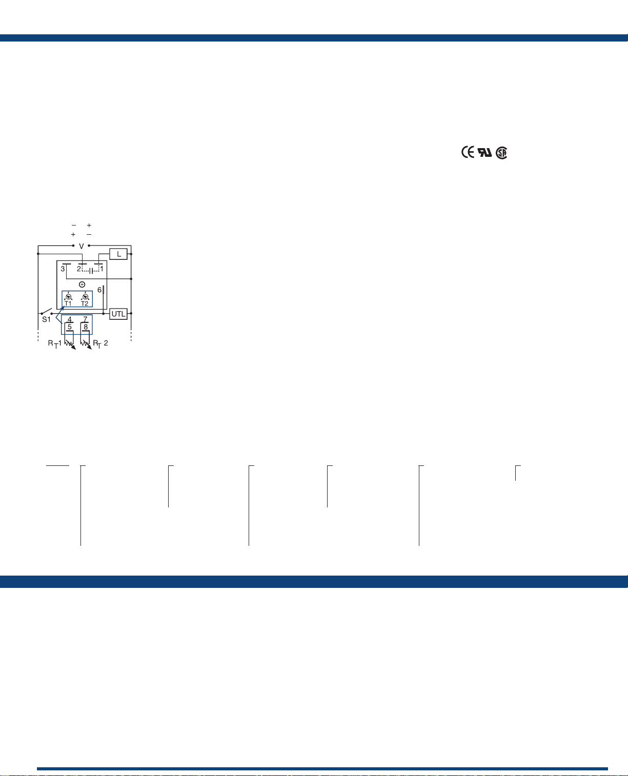
(Positive Switching)
Connection:
L1 N/L2
Terminal Location for
External Adjustment.
V = Voltage
L = Load
S1 = Initiate Switch
UTL = Untimed Load
T1 & R
1 = First Adjustment
T
T2 & R
2 = Second Adjustment
T
(Negative Switching)
The KSPD Series is a factory programmed module
available with 1 of 12 standard dual functions.
The time delays can be factory xed, externally
or onboard adjustable, or a combination of
xed and adjustable. The 1A steady, 10A inrush
rated solid-state output provides 100 million
operations, typical. Its microcontroller timing
circuit provides excellent repeat accuracy and
stability. Encapsulation protects against shock,
vibration, and humidity. The KSPD Series is a
cost effective approach for OEM applications that
require small size and long life.
See Appendix B, page 165, Figure 1 for dimensional
drawing.
Features:
• Choose 1 of 12 standard dual functions
• Special time ranges & functions available
• Factory programmed
• Microcontroller circuitry, ±0.5% repeat
accuracy
• 1A steady, solid-state output , 10A inrush
• 12 to 240V in 3 options
• Delays from 0.1s - 1000h in 9 ranges
Approvals:
Auxiliary Products:
• External ad just potentiometer:
P/N: P1004-95
P/N: P1004-95-X
• Versa-knob: P/N: P0700-7
• Female quick connect:
P/N: P101 5-64 (AWG 14/16)
• Quick connect to screw adaptor:
P/N: P1015-18
• DIN rail: P/N: C103PM (Al)
• DIN rail adaptor: P/N: P1023-20
Available Models:
KSPD32221RXD
KSPD4175S130SMS
KSPD42121MB
KSPDA110ST00127
KSPDA114ST00173
KSPDA2121RXE
If desired part number is not listed, please call us to
see if it is technically possible to build.
KSPDA2222RXE
KSPDP10.1S31RXE
KSPDP110M18SRXD
KSPDP110M18SRXE
KSPDP3131MI
Order Table:
KSPD
X
Input
─A - 24 to 240VAC
─P - 12 to 120VDC
positive switching
─N - 12 to 120VDC
negative switching
─1 - 120VDC
positive switching
─3 - 24VDC
─4 - 120VAC
X
First Adjustment
(T1 or RT1)
─1 - Fixed
─2 - Onboard adjust
─3 - External adjust
*If xed delay is selected, insert delay (0.1-999)
followed by (S) secs., or (M) mins., or (H) hrs.
X
First Time Delay*
─1 - 0.1 - 10s
─2 - 1 - 100s
─3 - 10 - 1000s
─4 - 0.1 - 10m
─5 - 1 - 100m
─6 - 10 - 1000m
─7 - 0.1 - 10h
─8 - 1 - 100h
─9 - 10 - 1000h
Specications
Time Delay
Type ...............................Microcontroller circuitry
Range ..............................0.1s - 1000h in 9 adjustable ranges or xed (to 999)
Repeat Accuracy ....................±0.5% or 20ms, whichever is greater
Tolerance (Factory Calibration) ........≤ ±2%
Reset Time ..........................≤ 150ms
Initiate Time ........................≤ 20ms; ≤ 1500 operations per minute
Time Delay vs Temp. & Voltage .......≤ ±2%
Input
Voltage. . . . . . . . . . . . . . . . . . . . . . . . . . . . . 12 to 120VDC; 24 to 240VAC
Tolerance ...........................≤ ±15%
AC Line Frequency / DC Ripple .......50/60Hz / ≤ 10%
Power Consumption ................AC ≤ 2VA; DC ≤ 1W
Output
Type ...............................Solid-state output
Rating .............................1A steady, 10A inrush for 16ms
X
Second Adjustment
(T2 or RT2)
─1 - Fixed
─2 - Onboard adjust
─3 - External adjust
Voltage Drop .......................AC ≅ 2.5V @ 1A; DC ≅ 1V @ 1A
OFF State Leakage Current ...........AC ≅ 5mA @ 230VAC; DC ≅ 1mA
Protection
Circuitry ...........................Encapsulated
Dielectric Breakdown ................
Insulation Resistance .................≥ 100 MΩ
Polarity ............................DC units are reverse polarity protected
Mechanical
Mounting ..........................Surface mt. with one #10 (M5 x 0.8) screw
Dimensions .........................2 x 2 x 1.21 in. (50.8 x 50.8 x 30.7 mm)
Termination ........................0.25 in. (6.35 mm) male quick connects
Environmental
Operating / Storage Temperature .....-40° to 60°C / -40° to 85°C
Humidity ...........................95% relative, non-condensing
Weight .............................≅ 2.4 oz (68 g)
X
Second Time Delay*
─1 - 0.1 - 10s
─2 - 1 - 100s
─3 - 10 - 1000s
─4 - 0.1 - 10m
─5 - 1 - 100m
─6 - 10 - 1000m
─7 - 0.1 - 10h
─8 - 1 - 100h
─9 - 10 - 1000h
For a complete list of functions with descriptions and diagrams,
see Appendix A - Timer Functions, pages 156-164.
≥ 2000V RMS terminals to mounting surface
X
Function
─Specify function
Functions:
MB, MRE, MI, MS,
IRE, BRE, SRE, RXE,
RXD, IM, AMI, SL
 Loading...