

Page 1
KSD3 SeriesTimer - Recycling Flasher
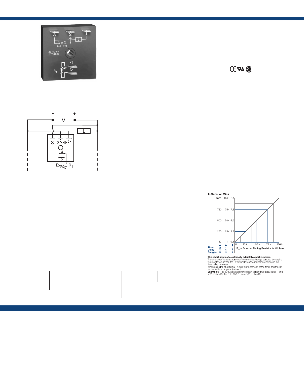
Connection:
RT is used when external adjustment is ordered.
L1 N/L2
The KSD3 Digi-Timer is a cost effective approach
for ON/OFF recycling applications. The on time
is equal to the off time. An adjustment of the RT
will change the time delays of both on and off
times. This series is designed for general purpose
commercial and industrial applications where a
small, cost effective, reliable, solid-state timer is
required. The factory calibration for xed time
delays is within 5% of the target time delay. The
repeat accuracy, under stable conditions, is 0.5% of
the selected time delay. This series is designed for
popular AC and DC voltages. Time delays of 0.1
seconds to 1000 minutes are available in 6 ranges.
The output is rated 1A steady and 10A inrush. The
modules are totally solid state and encapsulated
to protect the electronic circuitry.
Operation (Recycling Flasher - ON Time First):
Upon application of input voltage, the output energizes
and the T1, ON time begins. At the end of the ON time,
the output de-energizes and the T2 OFF time begins. At
the end of the OFF time, the output energizes and the cycle
repeats as long as input voltage is applied.
Reset: Removing input voltage resets the output and time
delays, and returns the sequence to the ON time.
Operation (Recycling Flasher - OFF Time First):
Upon application of input voltage, the T2 OFF time
begins. At the end of the OFF time, the T1 ON time
begins and the load energizes. At the end of the ON time
the load de-energizes, and the cycle repeats until input
voltage is removed.
Reset: Removing input voltage resets the output and time
delays and the sequence to the OFF time.
For more information see:
Appendix A, pages 156-164 for function descriptions
and diagrams.
Appendix B, page 165, Figure 1 for dimensional drawing.
Features:
• Fixed or adjustable delays from 0.1s -1000m
• Equal on and off delays
• ±0.5% repeat accuracy
• ± 5% factory calibration
• 12 to 120V in 4 ranges
• 1A, solid-state output
• Encapsulated
Approvals:
Auxiliary Products:
• External adjust potentiometer:
P / N: P 10 04 -9 5
P/N: P1004-95-X
• Female quick connect:
P / N : P 1 0 1 5 -6 4 ( AW G 1 4 / 1 6 )
• Quick connect to screw adaptor:
P/N: P1015-18
• Mounting bracket: P/N: P1023-6
• Versa-knob: P/N: P0700-7
• DIN rail: P/N: C103PM (Al)
• DIN rail adaptor: P/N: P1023-20
Available Models:
KSD3120A
KSD3310.1SA
KSD3410.5SA
KSD3432A
If desired part number is not listed, please call us
to see if it is technically possible to build.
External Resistance vs. Time Delay:
Order Table:
KSD3
X
Input Voltage
─1 - 12VDC
─2 - 24VAC
─3 - 24VDC
─4 - 120VAC
Note: DC voltages
available in negative
switching only
X
Adjustment
─1 - Fixed
─2 - External adjust
─3 - Onboard adjust
X
Time Delay*
─0 - 0.1 - 10s
─1 - 1 - 100s
─2 - 10 - 1000s
─3 - 0.1 - 10m
─4 - 1 - 100m
─5 - 10 - 1000m
Specications
Time Delay
Range ............................................................0.1s - 1000m in 6 adjustable ranges or xed
Repeat Accuracy .........................................±0.5% or 20ms, whichever is greater
Tolerance (Factory Calibration) ................≤ ± 5%
Reset Time ....................................................≤ 150ms
Time Delay vs Temp. & Voltage ................≤ ±10%
Input
Voltage ..........................................................24 or 120VAC; 12 or 24VDC
Tolerance ......................................................±20%
AC Line Frequency .....................................50/60 Hz
Power Consumption ..................................AC ≤ 2VA; DC ≤ 1W
Output
Type...............................................................Solid state
Maximum Load Current ............................1A steady state, 10A inrush at 60°C
OFF State Leakage Current .......................AC ≅ 5mA @ 230VAC; DC ≅ 1mA
X
Operating Sequence
─A - ON time rst
─B - OFF time rst
*If xed delay is selected, insert
delay (0.1 - 1000) followed by
(S) sec. or (M) min.
Voltage Drop ................................................AC ≅ 2.5V @ 1A; DC ≅ 1V @ 1A
DC Operation ..............................................Negative switching only
Protection
Circuitry .......................................................Encapsulated
Dielectric Breakdown .................................≥ 2000V RMS terminals to mounting surface
Insulation Resistance ..................................≥ 100 MΩ
Polarity .........................................................DC units are reverse polarity protected
Mechanical
Mounting .....................................................Surface mount with one #10 (M5 x 0.8) screw
Dimensions ..................................................2 x 2 x 1.21 in. (50.8 x 50.8 x 30.7 mm)
Termination ..................................................0.25 in. (6.35 mm) male quick connect terminals
Environmental
Operating/Storage Temperature ..............-40° to 60°C / -40° to 85°C
Humidity ......................................................95% relative, non-condensing
Weight ...........................................................≅ 2.4 oz (68 g)
 Loading...