

Page 1
KRPD SeriesTimer
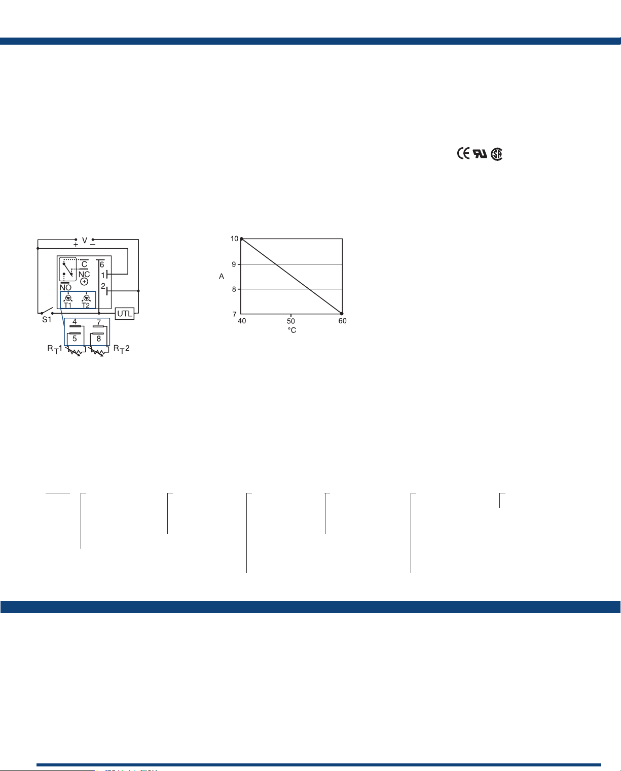
Connection:
L1 N/L2
V = Voltage
C = Common, Transfer Contact
NC = Normally Closed
NO = Normally Open
S1 = Initiate Switch
UTL = Untimed Load
A knob is supplied for adjustable units
or R
terminals for external adjust. The
T
untimed load is optional. S1 is not used
for some functions.
The KRPD Series is a factory programmed time
delay relay available with 1 of 12 standard dual
functions. The time delays can be factory xed,
onboard or externally adjustable or a combination
of xed and adjustable. The SPDT output relay
contacts offer a full 10A rating with complete
isolation. Its microcontroller timing circuit
provides excellent repeat accuracy and stability.
Encapsulation protects against shock, vibration,
and humidity. The KRPD Series is a cost effective
approach for OEM applications that require small
size, isolation, accuracy and long life.
See Appendix B, page 165, Figure 1 for dimensional
drawing.
Output Current/Ambient Temperature:
Features:
• Choose 1 of 12 standard dual functions
• Special time ranges & functions available
• Factory programmed
• Microcontroller circuitry, ±0.5% repeat
accuracy
• Isolated, 10A, SPDT output contacts
• Input voltage from 12 to 240V in 2 ranges
• Delays from 100ms - 1000h in 9 ranges
Approvals:
Auxiliary Products:
• External ad just potentiometer:
P/N: P1004-95
P/N: P1004-95-X
• Versa-knob: P/N: P0700-7
• Female quick connect:
P/N: P1015-64 (AWG 14/16)
• Quick connect to screw adaptor:
P/N: P1015-18
• DIN rail: P/N: C103PM (Al)
• DIN rail adaptor: P/N: P1023-20
Available Models:
KRPD12121MB
KRPD215S190SMB
KRPD417M113MRXD
KRPDA11M14MRXE
KRPDA175S130SMI
KRPDA2222RXE
If desired part number is not listed, please call us to
see if it is technically possible to build.
KRPDA2825AMI
KRPDA3232MB
KRPDA3434MB
KRPDD2121MB
KRPDD3232RXE
Order Table:
KRPD
X
Input
─A - 24 to 240VAC/DC
─D - 12 to 48VDC
─1 - 12VDC
─2 - 24VAC
─4 - 120VAC
─9 - 230VAC
X
First Adjustment
(T1 or RT1)
─1 - Fixed
─2 - Onboard adjust
─3 - External adjust
*If xed delay is selected, insert delay (0.1-999)
followed by (S) secs., or (M) mins., or (H) hrs.
X
First Time Delay*
─1 - 0.1 - 10s
─2 - 1 - 100s
─3 - 10 - 1000s
─4 - 0.1 - 10m
─5 - 1 - 100m
─6 - 10 - 1000m
─7 - 0.1 - 10h
─8 - 1 - 100h
─9 - 10 - 1000h
Specications
Time Delay
Type .............................Microcontroller circuitry
Range ............................0.1s - 1000h in 9 adjustable ranges or xed (to 999)
Repeat Accuracy ..................±0.5% or 20ms, whichever is greater
Tolerance (Factory Calibration) ......≤ ±2%
Reset Time ........................≤ 150ms
Initiate Time ......................≤ 40ms; 750 operations per minute
Time Delay vs Temp. & Voltage .....≤ ±2%
Input
Voltage. . . . . . . . . . . . . . . . . . . . . . . . . . . 12 to 48VDC; 24 to 240VAC/DC
Tolerance 12 to 48VDC ........-15% - 20%
24 to 240VAC/DC. . . . . . . . -20% - 10%
AC Line Frequency / DC Ripple .....50/60 Hz / ≤ 10%
Power Consumption ...............AC ≤ 2VA; DC ≤ 2W
Output
Type .............................Isolated relay contacts
Form .............................SPDT
X
Second Adjustment
(T2 or RT2)
─1 - Fixed
─2 - Onboard adjust
─3 - External adjust
Rating (at 40°C) ...................10A resistive @ 125VAC
5A resistive @ 230VAC & 28VDC
1/4 hp @ 125VAC
Max. Switching Voltage ............250VAC
Life (Operations) ..................Mechanical - 1 x 10
Protection
Circuitry .........................Encapsulated
Isolation Voltage ..................≥ 1500V RMS input to output
Insulation Resistance ...............≥ 100 MΩ
Polarity ..........................DC units are reverse polarity protected
Mechanical
Mounting ........................Surface mount with one #10 (M5 x 0.8) screw
Dimensions .......................2 x 2 x 1.21 in. (50.8 x 50.8 x 30.7 mm)
Termination ......................0.25 in. (6.35 mm) male quick connects
Environmental
Operating / Storage Temperature ...-40° to 60°C / -40° to 85°C
Humidity .........................95% relative, non-condensing
Weight ...........................≅ 2.6 oz (74 g)
X
Second Time Delay*
─1 - 0.1 - 10s
─2 - 1 - 100s
─3 - 10 - 1000s
─4 - 0.1 - 10m
─5 - 1 - 100m
─6 - 10 - 1000m
─7 - 0.1 - 10h
─8 - 1 - 100h
─9 - 10 - 1000h
For a complete list of functions with descriptions and diagrams,
see Appendix A - Timer Functions, pages 156-164.
X
Function
─Specify function
Functions:
MB, MRE, MI, MS,
IRE, BRE, SRE, RXE,
RXD, IM, AMI, SL
7
; Electrical - 1 x 10⁵
 Loading...