

Page 1
Dedicated
timers
Motion Detector - Retriggerable Single Shot
KRD9 Digi-Timer
Time Delay Relay
Description
The KRD9 Series microcontroller timing circuit provides excellent repeat accuracy and stability. Cost effective
approach for OEM applications that require small size, isolation, reliability, and long life.
Compact Time Delay Relay
Microcontroller Circuitry, +/-
0.5% Repeat Accuracy
Isolated 10 A SPDT
Output Contacts
Onboard or External
Adjustment or Fixed Time
Delay
Delays from 100 ms ...
1000 m in 6 Ranges
Input Voltages from 12 ...
230 V in 5 Ranges
Approvals:
Accessories
B
External adjust
potentiometer
P/Ns:
P1004-95 (fig A)
A
P1004-95-X (fig B)
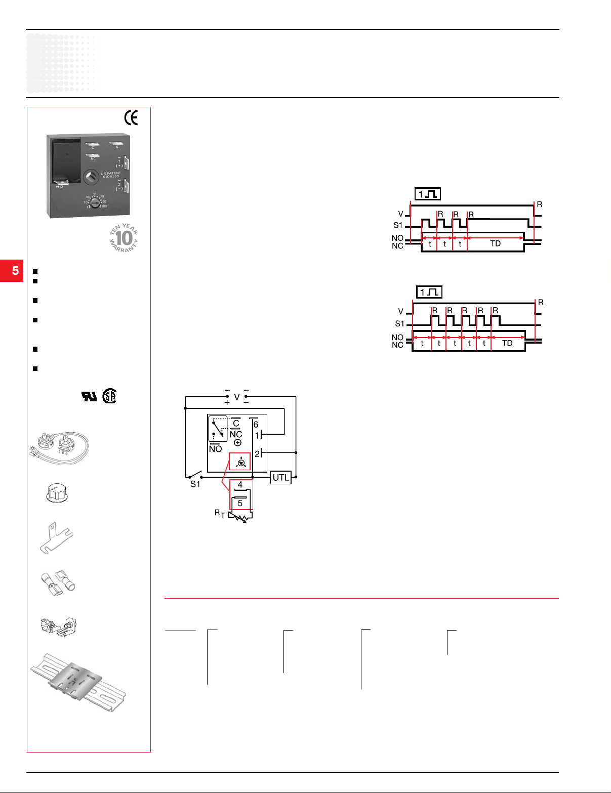
Operation- Retriggerable Single Shot
Function Type A (Output Initially De-energized):
Input voltage must be applied prior to and during
timing. When the initiate switch is closed, (momentary
or maintained) the output energizes and the time delay
starts. On completion of the delay, the output deenergizes. The unit will time out if S1 remains in the
open or closed position for the full time delay. Reclosing
the initiate switch resets the time delay and restarts
timing; the output remains energized. The output will
not energize if the initiate switch is closed when input
voltage is applied.
Function Type B (Output Initially Energized): Upon
application of input voltage, the output energizes and
the time delay starts. At the end of the time delay,
the load de-energizes. The unit will time out if S1
remains in the open or closed position for the full time
delay. Closing (re-closing) the initiate switch resets
the time delay and restarts timing; the output remains
energized.
Reset: The time delay and the output are reset when
input voltage is removed.
Connection
Function
Motion Detector/
Retriggerable Single Shot
De-energized
Motion Detector/
Retriggerable Single Shot
Energized
V = Voltage S1 = Initiate Switch
R = Reset TD = Time Delay
t = Incomplete Time Delay
NO = Normally Open NC = Normally Closed
Versa-knob
P/N: P0700-7
Mounting bracket
P/N: P1023-6
Female quick
connect
P/Ns:
P1015-64
(AWG 14/16)
P1015-13 (AWG 10/12)
C = Common, Transfer Contact UTL = Untimed Load
A knob is supplied for adjustable units, or R
terminals 4
T
& 5 for external adjust. See external adjustment vs time
delay chart. The untimed load is optional. Dashed lines
are internal connections. Relay contacts are isolated.
Ordering Table
Quick connect to
screw adaptor
P/N: P1015-18
DIN rail P/Ns:
017322005 (Steel)
C103PM (Al)
←
KRD9
Series
X
Input Function Type
–1 - 12 V DC
–2 - 24 V AC/DC
–4 - 120 V AC
–5 - 110 V DC
–6 - 230 V AC
X
Adjustment
–1 - Fixed
–2 - Onboard
Adjustment
–3 - External
Adjustment
→
DIN rail adaptor
P/N: P1023-20
See accessory pages for
specifications.
5.98 Low Voltage Products & Systems
1TRC 001 009 C0202 ABB Inc. • 888-385-1221 • Technical assistance 800-377-7722 • www.ssac.com
Example P/N:
KRD9421A = 120 V AC; Onboard adjust from 1 to 100 seconds, De-energized Function
KRD9610.5SB = 230 V AC, Fixed at 0.5 seconds, Energized Function
X
Time Delay *
–0 - 0.1 ... 10 s
–1 - 1 ... 100 s
–2 - 10 ... 1000 s
–3 - 0.1 ... 10 m
–4 - 1 ... 100 m
–5 - 10 ... 1000 m
X
–A - De-energized
–B - Energized
* If Fixed Delay is selected,
insert delay [0.1 … 1000]
followed by (S) sec. or
(M) min.
KRD9Gen 08.15.06
Page 2
Motion Detector - Retriggerable Single Shot
KRD9 Digi-Timer
Time Delay Relay
Technical Data
Time Delay
Type Microcontroller based with watchdog circuitry
Range 0.1 s ... 1000 m in 6 adjustable ranges or fixed
Repeat Accuracy +/-0.5% or 20 ms, whichever is greater
Tolerance (Factory Calibration) ≤ +/-5%
Reset Time ≤ 150 ms
Initiate Time ≤ 40 ms; ≤ 750 operations per minute
Time Delay vs. Temperature & Voltage ≤ +/-5%
Input
Voltage
Tolerance 12 V DC & 24 V DC/AC -15% ... +20%
110 VDC, 120 or 230 V AC -20% ... +10%
AC Line Frequency / DC Ripple 50 ... 60 Hz / ≤ 10%
Power Consumption AC ≤ 2 VA; DC ≤ 2 W
Output
Type Isolated relay contacts
Form Single pole double throw (SPDT)
Rating (at 40°C) 10 A resistive at 125 V AC
5 A resistive at 230 V AC & 28 V DC; 1/4 hp at 125 V AC;
Max. Switching Voltage 250 V AC
Life (Operations) Mechanical -- 1 x 10⁷ ; Electrical -- 1 x 10⁵
Protection
Circuitry Encapsulated
Isolation Voltage ≥ 1500 V RMS input to output
Insulation Resistance ≥ 100 MΩ
Polarity DC units are reversed polarity protected
Mechanical
Mounting Surface mount with one #10 (M5 x 0.8) screw
Package 2 x 2 x 1.21 in. (50.8 x 50.8 x 30.7 mm)
Termination 0.25 in. (6.35 mm) male quick connect terminals
Environmental
Operating/Storage Temperature -40°C ... +60°C/-40°C ... +85°C
Humidity 95% relative, non-condensing
Weight ≅ 2.6 oz (74 g)
12, 24 or 110 V DC; 24, 120 or 230 V AC
Dedicated
timers
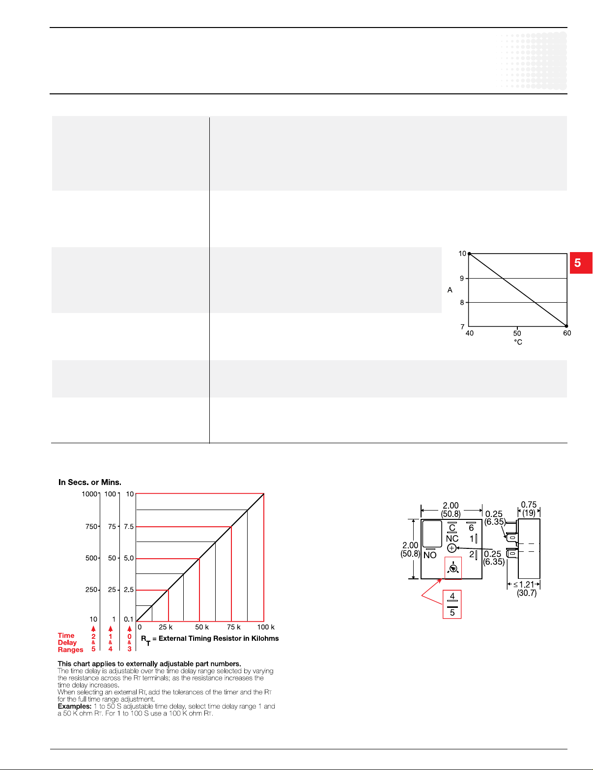
Output Current / Ambient Temp.
External Resistance vs Time Delay
KRD9Gen 08.15.06
Low Voltage Products & Systems 5.99
ABB Inc. • 888-385-1221 • Technical assistance 800-377-7722 • www.ssac.com 1TRC 001 009 C0202
Mechanical View
External Adjust Detail
Replaces Knobs if Ordered
Inches (Millimeters)
 Loading...