

Page 1
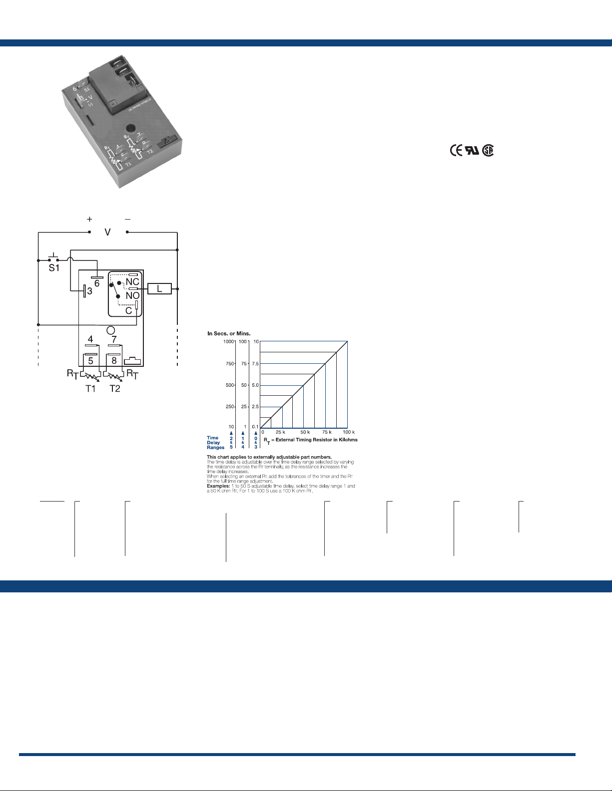
HRDR SeriesTimer - Recycling
Connection:
L1 N/L2
NO = Normally Open
S1 = Reset Switch
C = Common, Transfer Contact
L = Load
Terminals 4 & 5 and/or 7 & 8 are only included
on externally adjustable units.
Relay contacts are non-isolated. RT is included
when external adjustment is ordered. Terminal 6 is
included when Bypass/Reset is selected.
The HRDR Series combines an electromechanical
relay and microcontroller timing circuitry. It offers
12 to 230V operation in ve ranges and factory
fixed, onboard or externally adjustable time
delays with a repeat accuracy of ±0.5%. The high
switching capacity of the output contacts allow
for direct control of heavy loads like compressors,
pumps, motors, heaters and lighting. A bypass/
reset switch option allows operator to interrupt
normal recycling sequence and energize output
relay. An excellent choice for OEM applications.
Operation (Recycling with Reset Switch):
Upon application of input voltage, the ON time T1 begins
and output relay energizes. At the end of the ON time,
the output relay de-energizes and the OFF time T2 begins.
At the end of the OFF time, the output relay energizes
and the cycle repeats as long as input voltage is applied.
Some recycling timers have the OFF time as the rst delay.
Reset: Removing input voltage resets output and time
delays, and returns sequence to the rst delay.
Bypass/Reset Switch: Closing the normally open bypass/
reset switch energizes the output relay and resets the time
delays. Opening the switch restarts recycling operation
with the rst delay.
For more information see:
Appendix A, pages 156-164 for function descriptions
and diagrams.
Appendix B, page 165, Figure 2 for dimensional drawing.
External Resistance vs. Time Delay:
Features
• 30A, SPDT, NO output contacts
• 12 to 230V operation in 5 options
• Encapsulated circuitry
• Delays from 0.1s - 1000m in 6 ranges
• Independent adjustment of on and off delays
• ±0.5% repeat accuracy
• ±5% factory calibration
• Factory xed, onboard or external adjust
Approvals:
Auxiliary Products:
• External adjust potentiometer:
P / N: P1 0 0 4- 95
P/N: P1004-95-X
• Female quick connect:
P / N : P 1 0 1 5- 1 3 ( A W G 1 0 / 12 )
P / N : P 1 0 1 5- 6 4 ( A W G 1 4 / 16 )
• Quick connect to screw adaptor:
P/N: P1015-18
• Versa-knob: P/N: P0700-7
• Mounting bracket: P/N: P1023-6
• DIN rail: P/N: C103PM (Al)
• DIN rail adaptor: P/N: P1023-20
Available Models:
HRDR11720MB60S
HRDR120A1R
HRDR121A4R
HRDR130A0R
HRDR321A4R
HRDR322B2R
If desired part number is not listed, please call us to
see if it is technically possible to build.
HRDR330A0R
HRDR331A1
HRDR4110MB20M
HRDR431A1R
Order Table:
HRDR
X
Input
Voltage
─1 - 12VDC
─2 - 24VAC
─3 - 24VDC
─4 - 120VAC
─6 - 230VAC
X
External Adjust
─1 - Both Times Fixed
─2 - Both Times Onboard Adj.
─3 - Both Times External Adj.
─4 - ON Time External Adj.
OFF Time Fixed
─5 - ON Time Fixed
OFF Time External Adj.
─6 - ON Time Onboard Adj.
OFF Time Fixed
─7 - ON Time Fixed
OFF Time Onboard Adj.
─8 - ON Time Onboard Adj.
OFF Time External Adj.
─9 - ON Time External Adj.
OFF Time Onboard Adj.
Specications
Time Delay
Range ..................................100ms - 1000m in 6 adjustable ranges or xed
Repeat Accuracy ........................±0.5% or 20ms, whichever is greater
Tolerance (Factory Calibration) ............±5%
Reset Time ..............................≤ 150ms
Time Delay vs Temp. & Voltage ...........≤ ±2%
Input
Voltage. . . . . . . . . . . . . . . . . . . . . . . . . . . . . . . . . 12 or 24VDC; 24, 120, or 230VAC
Tolerance 12VDC & 24VDC ........-15% - 20%
24 to 230VAC ........-20% - 10%
AC Line Frequency ......................50/60 Hz
Power Consumption .....................AC ≤ 4VA; DC ≤ 2W
Output
Type ...................................Electromechanical relay
Form ...................................SPDT, non-isolated
Ratings: SPDT- NO SPDT-NC
General Purpose 125/240VAC 30A 15A
Resistive 125/240VAC 30A 15A
28VDC 20A 10A
Motor Load 125VAC 1 hp* 1/4 hp**
240VAC 2 hp** 1 hp**
80
X
T1 ON Time*
─0 - 0.1 - 10s
─1 - 1 - 100s
─2 - 10 - 1000s
─3 - 0.1 - 10m
─4 - 1 - 100m
─5 - 10 - 1000m
Life ....................................Mechanical - 1 x 10⁶;
Protection
Surge ..................................IEEE C62.41-1991 Level A
Circuitry ...............................Encapsulated
Dielectric Breakdown ....................≥ 2000V RMS terminals to mounting surface
Insulation Resistance .....................≥ 100 MΩ
Polarity ................................DC units are reverse polarity protected
Mechanical
Mounting ..............................Surface mount with one #10 (M5 x 0.8) screw
Dimensions .............................3 x 2 x 1.5 in. (76.7 x 51.3 x 38.1mm)
Termination ............................0.25 in. (6.35 mm) male quick connect terminals
Environmental
Operating / Storage Temperature .........-40° to 60°C / -40° to 85°C
Humidity ...............................95% relative non-condensing
Weight .................................≅ 3.9 oz (111 g)
X
Operating
Sequence
─A - ON time rst
─B - OFF time rst
*If xed delay is selected, insert delay (0.1 - 1000)
followed by (S) sec. or (0.1 - 1000) (M) min.
X
T2 OFF Time*
─0 - 0.1 - 10s
─1 - 1 - 100s
─2 - 10 - 1000s
─3 - 0.1 - 10m
─4 - 1 - 100m
─5 - 10 - 1000m
Electrical - 1 x 10
X
Operation
Reset Option
Option
5,
*3 x 10⁴, **6,000
─Blank - NoBypass/
─R - Bypass/Reset
www.ssac.com • 800-843-8848 • fax: 605-348-5685
Page 2
Appendix A - Timer Functions
Selecting a Timer’s Function
Selecting one of the ve most common timing functions can be as easy as answering three questions on the chart below. If you have trouble answering
these questions, try drawing a connection diagram that shows how the timer and load are connected. Time diagrams and written descriptions of the
ve most popular functions, plus other common functions. Instantaneous contacts, accumulation, pause timing functions, and ashing LED’s are
included in some units to expand the versatility of the timer. These expanded operations are explained on the product’s catalog page. Time diagrams
are used on these pages along with text and international symbols for functions.
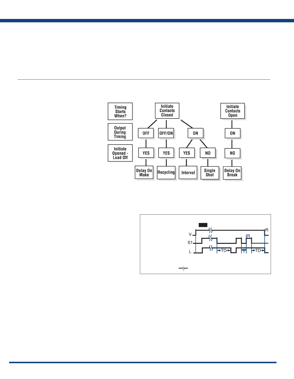
Function Selection Guide
Selection Questions
1) The timing starts when the
initiate (starting) contacts are:
A) Closed B) Opened
2) What is the status of the output
(or load) during timing:
A) On B) Off C) On/Off
3) Will the load de-energize
(or remain de-energized)
if the initiate (starting) contacts
are opened during timing:
A) Yes B) No
Understanding Time Diagrams
Time diagrams are used to show the relative operation of switches,
controls, and loads as time progresses. Time begins at the rst vertical
boundary. There may be a line indicating the start of the operation or it
may just begin with the transition of the device that starts the operation.
Each row in the time diagram represents a separate component.
These rows will be labeled with the name of the device or its terminal
connection numbers. In a bistable or digital system, the switches,
controls, or loads can only be ON or OFF. The time lines are drawn
to represent these two possible conditions. Vertical lines are used to
dene important starting or ending points in the operation.
The example to the right is the most common type of time diagram
in use in North America. It shows the energizing of loads, and the
closing of switches and contacts by an ascending vertical transition of
the time line. Opening switches or contacts or de-energizing loads are
represented by descending vertical transitions.
THE FIVE MOST USED FUNCTIONS
TIME DIAGRAM
Example:
Input Applied
Off
Initiate Closed
Switch Open
Output Energized
(Normally De-energized
Open)
R = Reset TD = Time Delay S1 = Initiate Switch
Undened time
Delay-on-Break (Release)
t = Incomplete Time Delay
156
www.ssac.com • 800-843-8848 • fax: 605-348-5685
Page 3
Accumulating
Delay-on-Make (Operate)
Appendix A - Timer Functions
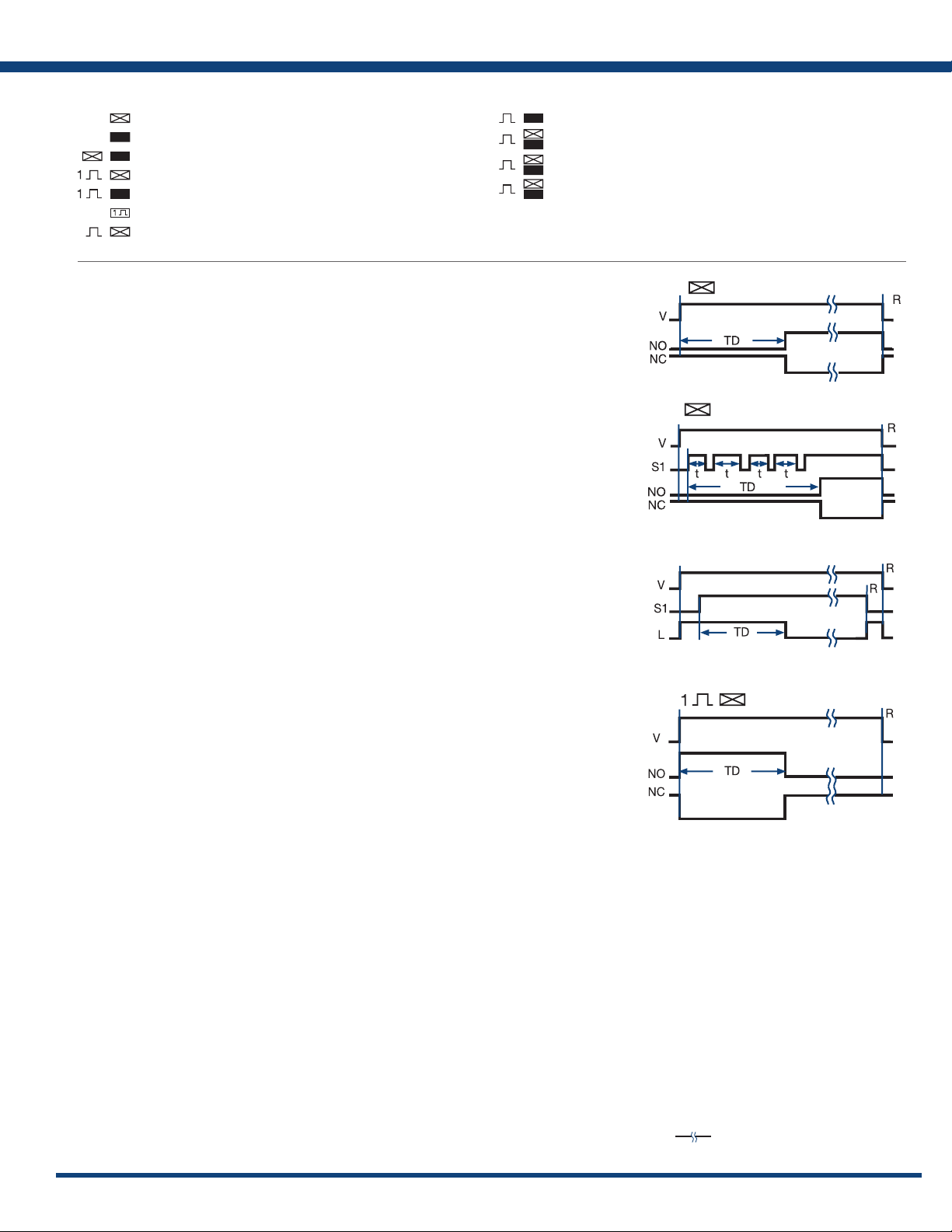
INTERNATIONAL TIMING FUNCTION SYMBOLS
= Delay-on-Make; ON-delay
= Delay-on-Break; OFF-delay
= Delay-on-Make & Break; ON and OFF-delay
= Interval; Impulse-ON
= Trailing Edge Interval; Impulse-OFF
= Single Shot; Pulse Former
= Flasher - ON Time First; Recycling Equal Times - ON First
®
Delay-on-Make: (ProgramaCube
(ON-delay, Delay on Operate, On Delay, Operate Delay, Delay On, Prepurge Delay)
OPERATION: Upon application of input voltage, the time delay begins. The output (relay or solid state)
is de-energized before and during the time delay. At the end of the time delay, the output energizes
and remains energized until input voltage is removed.
RESET: Removing input voltage resets the time delay and output.
See: HRPS, KRPS, KSPS, KSPU, NHPS, NHPU, TDM, TRDU
Function M)
Extra Functions Included in Some Delay-on-Make (DOM) Timers:
®
Accumulating Time Delay Feature: (ProgramaCube
Some DOM timers allow the time delay to be stopped and held and then resumed by opening and closing
an external switch. The total time delay, TD is the sum of the accumulated partial time delays, “t”.
See: KRPD, KRPS, HRPS, NHPS, KSPD, KSPS, TRDU
Function AM)
= Flasher - OFF Time First; Recycling Equal Times - OFF First
= Recycling - Unequal Times; Pulse Generator
= Recycling - Unequal Times Starting with ON or OFF
= Delay-on-Make & Interval; Single Pulse Generator
Delay-on-Make (ON-delay)
Instantaneous Contacts:
Some DOM timers have a set of instantaneous contacts in addition to the delayed contacts. Instantaneous
contacts energize when input voltage is applied and remain until voltage is removed.
Delay-on-Make, Normally Closed Output:
All relay output delay-on-make timers with normally closed contacts include this function. (See Delayon-Make NC Contacts) This function is also available in solid-state output timers. The solid-state output
energizes when input voltage is applied. The time delay begins when an optional initiate switch S1 is closed
(timing starts when voltage is applied if S1 is not used). The output de-energizes at the end of the time delay.
Reset: Opening S1 resets the time delay and the output immediately energizes (or remains energized).
Removing input voltage resets the time delay and de-energizes the output.
See: KSD4, THD4, TS4, TSD4
®
Interval: (ProgramaCube
(Impulse-ON, Single Pulse on Operate, On Interval, Interval On, Pulse Shaping, Bypass Timing)
OPERATION: Upon application of input voltage, the time delay begins. The output (relay or solid
state) energizes during the time delay. At the end of time delay the output de-energizes and remains
de-energized until input voltage is removed.
RESET: Removing input voltage resets the time delay and output.
See: HRPS, KRPS, KSPS, KSPU, NHPS, NHPU, TDI, TSD2
Function I)
Extra Functions Included on Some Interval Timers:
Instantaneous Contacts:
Some Interval timers have a set of intantaneous contacts in addition to the delayed contacts.
Intantaneous contacts energize when input voltage is applied and remain until voltage is removed.
Delay-on-Make (Normally Closed)
Interval (Impulse ON)
www.ssac.com • 800-843-8848 • fax: 605-348-5685
Legend
V = Voltage NO = Normally Open Contact
R = Reset NC = Normally Closed Contact
TD = Time Delay t = Incomplete (Partial) Time Delay
S1 = Initiate Switch
L = Load
= Undened time
157
Page 4

Appendix A - Timer Functions
Timer Functions
Popular Functions
Recycling: (ProgramaCube®Functions RE, RD, RXE, RXD)
(Flasher, Pulse Generator, Recycle Timing, Repeat Cycle, Duty Cycling)
OPERATION: Upon application of input voltage, the output (relay or solid state) energizes
and the ON time begins. At the end of the ON time, the output de-energizes and the OFF
time begins. At the end of the OFF time, the output energizes and the cycle repeats as long
as input voltage is applied. The OFF time may be the first delay in some recycling timers.
RESET: Removing input voltage resets the output and time delays, and returns the
sequence to the rst delay.
The time delays in some recycling timers are equal TD1=TD2. Flashers are an example of this type of
recycling timer. Others have separately selectable time delays.
See: HRPD, HRPS, KRPD, KRPS, KSPD, KSPS, KSPU, NHPD, NHPS, NHPU, TDR
Extra Functions Included in Some Recycling Timers:
Instantaneous Contacts:
Some Recycling timers have a set of instantaneous contacts in addition to the delayed contacts.
Instantaneous contacts energize when input voltage is applied and remain until voltage is removed.
RESET SWITCH: Closing an external switch transfers the output and resets the sequence to the rst delay.
See: HRDR
®
Delay-on-Break: (ProgramaCube
(Delay on Release, OFF-delay, Release Delay, Postpurge Delay)
OPERATION: Input voltage must be applied before and during timing. Upon closure of the initiate
switch, the output (relay or solid state) energizes. The time delay begins when the initiate switch is
opened. The output remains energized during timing. At the end of the time delay, the output deenergizes. The output will energize if the initiate switch is closed when input voltage is applied.
RESET: Reclosing the initiate switch during timing resets the time delay. Removing input voltage resets
the time delay and output.
See: HRPS, HRPU, KRPS, KSPS, KSPU, NHPS, NHPU, TRDU, TDB
Function B)
Recycling w/Reset Switch
Delay-on-Break (OFF-delay)
Extra Functions Included in Some Delay-on-Break (DOB) Timers:
Instantaneous Contacts:
Some DOB timers have a set of instantaneous contacts in addition to the delayed contacts. Instantaneous
contacts energize when input voltage is applied and remain until voltage is removed.
Related Functions:
Inverted Delay-on-Break: (ProgramaCube® Function UB)
OPERATION: Input voltage must be applied before and during timing. Upon closure of the initiate
switch S1, the output (relay or solid state) de-energizes. The time delay begins when S1 is opened. The
output remains de-energized during timing. At the end of the time delay, the output energizes. The
output remains de-energized if S1 is closed when input voltage is applied
RESET: Reclosing S1 during timing resets the time delay. Removing input voltage resets the time delay
and output.
See: HRPS, HRPU, KRPS, KSPS, KSPU, NHPS, NHPU, TRDU
Legend
V = Voltage
R = Reset
T1 = ON Time
T2 = OFF Time
S1 =Initiate Switch
Inverted Delay-on-Break
NO = Normally Open Contact
NC = Normally Closed Contact
t = Incomplete Time Delay
TD, TD1, TD2 = Time Delay
= Undened Time
158
www.ssac.com • 800-843-8848 • fax: 605-348-5685
Page 5

Appendix A - Timer Functions
®
Single Shot: (ProgramaCube
(Pulse Former, One Shot Relay, Single Shot Interval, Pulse Shaping)
OPERATION: Input voltage must be applied before and during timing. Upon momentary or maintained
closure of the initiate switch, the output (relay or solid state) energizes and the time delay begins. At
the end of the delay, the output de-energizes. Opening or reclosing the initiate switch during timing
has no effect on the time delay. Note (for most single shot timers): If the initiate switch is closed when
input voltage is applied, the output energizes and the time delay begins.
RESET: Reset occurs when the time delay is complete and the initiate switch is opened. Removing input
voltage resets the time delay and output.
See: HRPS, HRPU, KRPS, KSPS, KSPU, NHPS, NHPU, TDS, TSDS, TRDU
Extra Functions Included in Some Single Shot Timers:
Instantaneous Contacts:
Some Single Shot timers have a set of instantaneous contacts in addition to the delayed contacts.
Instantaneous contacts energize when input voltage is applied and remain until voltage is removed.
Functions S or SD)
Single Shot (Pulse Former)
Related Functions:
Retriggerable Single Shot (Motion Detector): (ProgramaCube
(Motion Detector, Zero Speed Switch, Watchdog Timer, Missing Pulse Timer)
OPERATION: Input voltage must be applied prior to and during timing. The output (relay or solid state)
is de-energized. When the initiate switch S1 closes momentarily or maintained, the output energizes
and the time delay begins. Upon completion of the delay, the output de-energizes.
RESET: Reclosing S1 resets the time delay and restarts timing. Removing input voltage resets the time
delay and output.
See: HRD9, HRPS, HRPU, KRD9, KRPS, KSPS, KSPU, NHPS, NHPU, TRDU, TRU
®
Retriggerable Single Shot (Motion Detector): (ProgramaCube
OPERATION: Similar to retriggerable single shot function PSD above except, when input voltage is applied,
the output (relay or solid state) immediately energizes and timing begins. At the end of the time delay, the
output de-energizes. The unit will timeout as long as S1 remains open or closed for a full time delay period.
RESET: During timing, reclosing S1 resets and restarts the time delay and the output remains energized.
After timeout, reclosing S1 starts a new operation. Removing input voltage resets the time delay and
the output.
See: KRD9
Function PSE)
®
Function PSD)
Inverted Single Shot: (ProgramaCube® Function US)
OPERATION: Input voltage must be applied before and during timing. Upon momentary or
maintained closure of the initiate switch S1, the output (relay or solid state) de-energizes. At the
end of the time delay, the output energizes. Opening or reclosing S1 during timing has no affect on
the time delay. The output will remain de-energized if S1 is closed when input voltage is applied.
RESET: Reset occurs when the time delay is complete and S1 is open. Removing input voltage resets
the time delay and output.
See: HRPS, HRPU, KRPS, KSPS, KSPU, NHPS, NHPU, TRDU
Motion Detector (PSD)
Retriggerable Single Shot
Motion Detector (PSE)
Retriggerable Single Shot
Inverted Single Shot
Trailing Edge Single Shot (Impulse-OFF): (ProgramaCube® Function TS)
OPERATION: Input voltage must be applied before and during timing. When the initiate switch
S1 opens, the output (relay or solid state) energizes. At the end of the time delay, the output
de-energizes. Reclosing and opening S1 during timing has no affect on the time delay. The output will
not energize if S1 is open when input voltage is applied.
RESET: Reset occurs when the time delay is complete and S1 is closed. Removing input voltage resets
the time delay and output.See: HRPS, KRPS, KSPS, KSPU, NHPU, TRDU
www.ssac.com • 800-843-8848 • fax: 605-348-5685
Trailing Edge Single Shot
159
Page 6

Appendix A - Timer Functions
Timer Functions
Two Functions in One Timer
®
Delay-on-Make/Delay-on-Break: (ProgramaCube
(ON-delay/OFF-delay, Delay on Operate/Delay on Release, Sequencing ON & OFF, Fan Delay,
Prepurge & Postpurge)
OPERATION: Input voltage must be applied at all times. The output (relay or solid state) is deenergized. Upon closure of the S1 initiate switch, the delay-on-make time delay (TD1) begins. At
the end of TD1, the output (relay or solid state) energizes. Opening S1 starts the delay-on-break time
delay (TD2). At the end of TD2, the output de-energizes.
RESET: Removing input voltage resets time delays and the output.If S1 is a) opened during TD1,
then TD1 is reset and the output remains de-energized. b) reclosed during TD2, then TD2 is reset
and the output remains energized.
See: HRPD, KRPD, KSPD, NHPD
Extra Functions Included in Some Delay-on-Make/Delay-on-Break Timers:
Instantaneous Contacts:
Some DOM/DOB timers have a set of instantaneous contacts in addition to the delayed contacts.
Instantaneous contacts energize when input voltage is applied and remain until voltage is removed.
Function MB)
Delay-on-Make/
Delay-on-Break
®
Delay-on-Make/Interval: (ProgramaCube
(Single Pulse Generator, Delayed Interval, Delay on Operate/Single Pulse on Operate)
OPERATION: Upon application of input voltage, the delay-on-make time delay (TD1) begins, the
output remains de-energized. At the end of this delay, the output (relay or solid state) energizes
and the interval delay (TD2) begins. At the end of the interval delay (TD2), the output de-energizes.
RESET: Removing input voltage resets the output, the time delays and returns the sequence to the
rst delay.
See: ESD5, HRPD, KRPD, KSPD, NHPD, TRDU
Accumulative Delay-on-Make/Interval: (ProgramaCube
OPERATION: Input voltage must be applied before and during timing. The output is de-energized before
and during the TD1 time delay. Each time S1 closes, the time delay progresses; when it opens, timing stops.
When the amount of time S1 is closed equals the full TD1 delay, the output (relay or solid state) energizes
for TD2. Upon completion of TD2, the output relay de-energizes. Opening S1 during TD2 has no affect.
RESET: Removing input voltage resets the time delay, output relay, and the sequence to the rst delay.
See: HRPD, KRPD, KSPD, NHPD
Function MI)
®
Function AMI)
Legend
V = Voltage
S1 = Initiate Switch
R = Reset
TD1, TD2 = Time Delay
NO = Normally Open
NC = Normally Closed
= Undened Time
Delay-on-Make/
Interval
Accumulative Delay-on-Make/
Interval
160
www.ssac.com • 800-843-8848 • fax: 605-348-5685
Page 7

Timer Functions
Two Functions in One Timer
Appendix A - Timer Functions
®
Delay-on-Make/Recycle: (ProgramaCube
OPERATION: Upon application of input voltage, TD1 begins and the output (relay or solid state) remains
de-energized. At the end of TD1, the TD2 recycle function begins and the output (relay or solid state)
cycles ON and OFF for equal delays. This cycle continues until input voltage is removed.
RESET: Removing input voltage resets the output and time delays, and returns the sequence to the
rst delay.
See: KSPD, KRPD, NHPD, HRPD, TRDU
Delay-on-Make/Single Shot: (ProgramaCube
OPERATION: Upon application of input voltage and the closure of S1, TD1 begins and the output (relay
or solid state) remains de-energized. The output (relay or solid state) energizes at the end of TD1, and
TD2 begins. At the end of TD2, the output (relay or solid state) de-energizes. Opening or reclosing S1
during timing has no affect on the time delays.
RESET: Reset occurs when the time delay is complete and S1 is open. Removing input voltage resets
the time delay, output, and the sequence to the rst delay.
See: KSPD, KRPD, NHPD, HRPD, TRDU
®
Interval/Recycle: (ProgramaCube
OPERATION: Upon application of input voltage TD1 begins. At the same time, the TD2 ON time begins
and the output (relay or solid state) energizes. At the end of the ON time, the TD2 OFF time begins and
the output de-energizes. The equal ON time OFF time cycle continues until TD1 is completed at which
time the output de-energizes.
RESET: Removing input voltage resets the time delays, output, and the sequence to the Interval function.
See: KSPD, KRPD, NHPD, HRPD, TRDU
Function IRE)
Delay-on-Break/Recycle: (ProgramaCube
OPERATION: Upon application of input voltage and the closure of S1, the TD2 ON time begins and
the output (relay or solid state) energizes. Upon completion of the ON time, the output de-energizes
for the TD2 OFF time. At the end of the OFF time, the equal ON/OFF cycle repeats. When S1 opens,
the TD1 delay begins. TD1 and TD2 run concurrently until the completion of TD1 at which time, the
TD2 ON/OFF cycle terminates and the output de-energizes. The output energizes if S1 is closed when
input voltage is applied.
RESET: Reclosing S1 during timing resets the TD1 time delay. Removing input voltage resets the time
delay, output, and the sequence to the Delay-on-Break function.
See: KSPD, KRPD, NHPD, HRPD, TRDU
Function MRE)
®
Function MS)
®
Function BRE)
Delay-on-Make
Recycle
Delay-on-Make
Single Shot
Interval
Recycle
Delay-on-Break
Recycle
®
Single Shot/Recycle: (ProgramaCube
OPERATION: Upon application of input voltage and the closure of S1, TD1 begins. At the same time,
the TD2 ON time begins and the output (relay or solid state) energizes. Upon completion of the ON
time, the output de-energizes for the TD2 OFF time. At the end of the OFF time, the equal ON/OFF
cycle repeats. TD1 and TD2 run concurrently until the completion of TD1 at which time, the TD2 ON/
OFF cycle terminates and the output de-energizes. Opening or reclosing S1 during timing has no affect
on the time delays. The output will energize if S1 is closed when input voltage is applied.
RESET: Removing input voltage resets the time delay, output, and the sequence to the rst delay.
See: HRPD, KRPD, KSPD, NHPD, TRDU
Function SRE)
Single Shot/Lockout: (ProgramaCube® Function SL)
OPERATION: Upon application of input voltage and momentary or maintained closure of S1, the output
(relay or solid state) energizes and TD1 single shot time delay begins. The output relay de-energizes at
the end of TD1 and the TD2 lockout time delay begins. During TD2 (and TD1) closing switch S1 has no
effect on the operation. After TD2 is complete, closing S1 starts another operation. If S1 is closed when
input voltage is applied, the output energizes and the TD1 time delay begins.
RESET: Removing input voltage resets the time delays and the output and returns the cycle to the rst
delay.
®
Interval/Delay-on-Make: (ProgramaCube
OPERATION: Upon application of input voltage, the output (relay or solid state) energizes and TD1
begins. At the end of TD1, the output de-energizes and TD2 begins. At the end of TD2, the output energizes.
RESET: Removing input voltage resets the time delays, output, and the sequence to the rst delay.
See: HRPD, KRPD, KSPD, NHPD, TRDU
www.ssac.com • 800-843-8848 • fax: 605-348-5685
Function IM)
Single Shot
Recycle
Single Shot
Lockout
Interval
Delay-on-Make
161
Page 8

Appendix A - Timer Functions
Timer Functions
Counting and Switching Functions
®
Leading edge ip-op: (ProgramaCube
OPERATION: Input voltage must be applied before and during operation. The operation begins with
the output (relay or solid state) de-energized. Upon momentary or maintained closure (leading edge
triggered) of the initiate switch S1, the time delay begins. At the end of the time delay, the output
energizes and remains energized. Opening or re-closing S1 during timing has no affect. After the output
transfers, the next closure of S1 starts a new operation. Each time an S1 closure is recognized, the time
delay occurs and then the output transfers, ON to OFF, OFF to ON, ON to OFF. The rst operation will
occur if S1 is closed when input voltage is applied.
RESET: Removing input voltage resets the time delay and the output to the de-energized state.
Function can be applied to ProgramaCube Series: HRPS, KRPS, KSPS
Alternating Relay (Trailing edge ip-op): (ProgramaCube
OPERATION: Input voltage must be applied at all times for proper operation. The operation begins
with the output (relay or solid state) de-energized. Closing S1 enables the next alternating operation.
When S1 opens (trailing edge triggered), the time delay begins. At the end of the time delay, the output
energizes and remains energized until S1 is (re-closed and) re-opened. Then the output relay de-energizes
and remains until S1 opens again. Each time S1 opens the time delay occurs and the output transfers.
RESET: Removing input voltage resets the output and the time delay.
See: ARP, HRPS, KRPS
Function F)
®
Function FT)
Leading Edge Flip-Flop
Trailing Edge Flip-Flop
(Alternating Relay)
®
Counter with Pulsed Output: (ProgramaCube
Function Limited to Switch Adjustable ProgramaCubes
OPERATION: Input voltage must be applied before and during operation. Each time S1 is closed, a count
is added. When the total number of S1 closures equals the total count selected on the unit, the output
energizes. The output remains energized for the pulse duration specied for the product, and then deenergizes. If S1 is closed while the output is energized, a count is not added. If S1 is closed when input
voltage is applied, a count is not added.
RESET: The unit automatically resets at the end of each operation. Removing input voltage resets the
output, counter, and pulse delay.
See: HRPU, KSPU, NHPU
Counter with Interval Output: (ProgramaCube
Function Limited to Switch Adjustable ProgramaCubes
OPERATION: Input voltage must be applied before and during operation. Each time S1 is closed, a count
is added. When the total number of S1 closures equals the total count selected on the unit, the output
energizes and the interval time delay begins. The output de-energizes at the end of the time delay. If
S1 is closed during the time delay, a count is not added. If S1 is closed when input voltage is applied,
a count is not added.
RESET: The counter is reset during the time delay, the unit automatically resets at the end of the interval
time delay. Removing input voltage resets the output, counter, and time delay.
See: HRPU, HRV, HSPZ, KSPU, NHPU
Function C)
®
®
Function CI)
®
Counter with Pulsed Output
Counter with Interval Output
Legend
V = Voltage
R = Reset
S1 = Initiate Switch
Td, TD1, TD2 = Time Delay
NO = Normally Open Contact
NC = Normally Closed Contact
C = Count
P = Pulse Duration
= Undened Time
162
www.ssac.com • 800-843-8848 • fax: 605-348-5685
Page 9

Appendix B - Dimensional Drawings
FIGURE 1 FIGURE 2 FIGURE 3
CT; ESD5; ESDR; FS100; FS200; FS300; KRD3; KRD9;
KRDB; KRDI; KRDM; KRDR; KRDS; KRPD; KRPS;
KSD1; KSD2; KSD3; KSD4; KSDB; KSDR; KSDS;
KSDU; KSPD; KSPS; KSPU; KVM; T2D; TA; TAC1;
TAC4; TDU; TDUB; TDUI; TDUS; TL; TMV8000;
TS1; TS2; TS4; TS6; TSB; TSD1; TSD2; TSD3; TSD4;
TSD6; TSD7; TSDB; TSDR; TSDS; TSS; TSU2000
FIGURE 4 FIGURE 5
TRDU
FA; FS; FSU1000*; NHPD; NHPS; NHPU;
NLF1*; NLF2*; PHS*; PTHF*; SIR1; SIR2;
SLR1*; SLR2*; TH1; TH2; THC; THD1;
THD2; THD3; THD4; THD7; THDB; THDM;
THDS; THS
*If unit is rated @ 1A, see Figure 1
FIGURE 7
FIGURE 8 FIGURE 9
HLV; HRD3; HRD9; HRDB; HRDI;
HRDM; HRDR; HRDS; HRID; HRIS;
HRIU; HRPD; HRPS; HRPU; HRV; RS
HSPZ
FIGURE 6
TRU
(snap for
mounting
bases)
PLM; PLR; TDB; TDBH; TDBL; TDI; TDIH;
TDIL; TDM; TDMB; TDMH; TDML; TDR;
TDS; TDSH; TDSL
ASQU; ASTU; DSQU; DSTU
FIGURE 11
FIGURE 10
ERD3; ERDI; ERDM ORB; ORM; ORS
www.ssac.com • 800-843-8848 • fax: 605-348-5685
FS500; PRLB; PRLM; PRLS; TRB; TRM; TRS
FIGURE 12
FS100; FS400
inches (millimeters)
165
 Loading...