

SSAC HRDB Power-Time Catalog Page
Delay On Break (Release)
HRDB Power-Time
Time Delay Relay
Description
The HRDB Series combines an electromechanical relay output with microcontroller timing circuitry. The HRDB
offers 12 to 230 V operation in five ranges and factory fixed, external, or onboard adjustable time delays with
a repeat accuracy of +/-0.5%. The isolated output contact rating allows for direct operation of heavy loads
such as compressors, pumps, blower motors, heaters, etc. The HRDB is ideal for OEM applications where
cost is a factor.
30 A SPDT N.O. Isolated
Output Contacts
12 ... 230 V Operation in
5 Ranges
Delays from 100 ms ...100 m
in 5 Ranges
+/-0.5% Repeat Accuracy
Fixed, External, or Onboard
Adjustment
Approvals:
Accessories
B
External adjust
potentiometer
P/Ns:
A
P1004-95 (fig A)
P1004-95-X (fig B)
Mounting bracket
P/N: P1023-6
Female quick
connect P/Ns:
P1015-64
P1015-13
Quick connect to
screw adaptor
P/N: P1015-18
Versa-knob
P/N: P0700-7
DIN rail P/Ns:
017322005 (Steel)
C103PM (Al)
(AWG 14/16)
(AWG 10/12)
←
→
DIN rail adaptor
P/N: P1023-20
See accessory pages for
specifications.
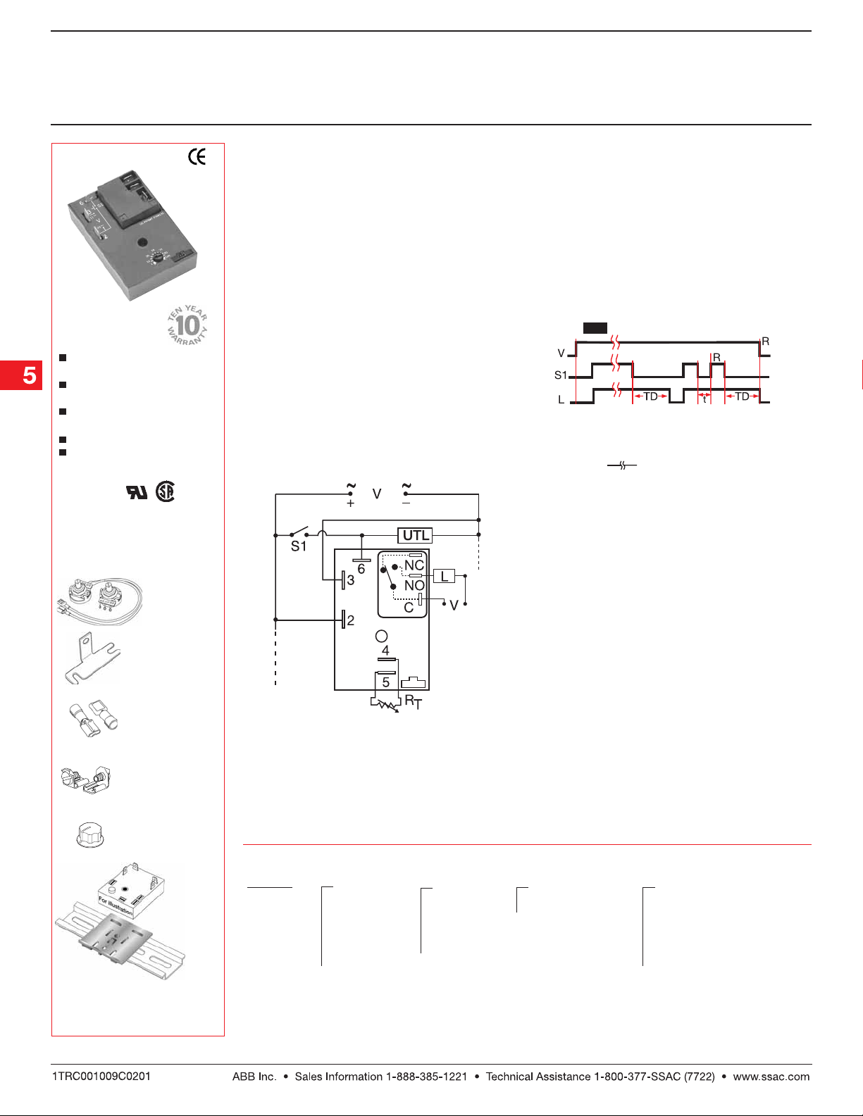
Operation
Function
Input voltage must be applied before and during
timing. Upon closure of the initiate switch, the output
relay energizes. The time delay begins when the initiate
switch is opened. The output remains energized
during timing. At the end of the time delay, the output
de-energizes. The output will energize if the initiate
switch is closed when input voltage is applied.
Reset: Reclosing the initiate switch during timing resets
the time delay. Loss of input voltage resets the time
delay and output.
V = Voltage L = Load S1 = Initiate Switch
TD = Time Delay R = Reset
t = Incomplete Time Delay
Connection
S1 = Initiate Switch L = Timed Load
UTL = Untimed Load NO = Normally Open
C = Common, Transfer Contact
NOTE: A knob, or terminals 4 & 5 are only included
on adjustable units. RT is used when external
adjustment is ordered. Relay contacts are
isolated. Dashed lines are internal connections.
The untimed load is optional.
Ordering T able
HRDB X X X X
Series Input Adjustment Time Tolerance
Fixed
Onboard
Knob
External
Adjust
* If Fixed Delay is selected, insert delay
[0.1 … 1000] followed by (S) sec. or
[0.1 ... 100] (M) min.
Example P/N:
–1 - 12 V DC –1 -–A - +/-1% –0 - 0.1 ... 10 s
–2 - 24 V AC –2 - Blank - +/-5% –1 - 1 ... 100 s
–3 - 24 V DC –2 - 10 ... 1000 s
–4 - 120 V AC –3 - –3 - 0.1 ... 10 m
–6 - 230 V AC –4 - 1 ... 100 m
HRDB421 Fixed – HRDB41A0.5S
Delay On Break
= Undefined time
Time Delay*
HRDBGem 10.03.05
Low Voltage Products & Systems5.58
Delay On Break (Release)
HRDB Power-Time
Time Delay Relay
Technical Data
Time Delay
Type Microcontroller circuitry
Range 100 ms ... 100 m in 5 adjustable ranges or fixed
Repeat Accuracy +/-0.5 % or 20 ms, whichever is greater
Tolerance (Factory Calibration) +/-1%, +/- 5%
Reset Time ≤ 150 ms
Initiate Time ≤ 20 ms
Time Delay vs. Temperature & Voltage +/- 2%
Input
Voltage 12 or 24 V DC; 24, 120, or 230 V AC
Tolerance 12 V DC & 24 V DC -15% ... +20%
24 ... 230 V AC -20% ... +10%
Line Frequency 50 ... 60 Hz
Power Consumption AC ≤ 4 VA; DC ≤ 2 W
Output
Type Electromechanical relay
Form SPDT, isolated
Ratings: SPDT-N.O. SPDT-N.C.
General Purpose 125/240 V AC 30 A 15 A
Resistive 125/240 V AC 30 A 15 A
28 V DC 20 A 10 A
Motor Load 125 V AC 1 hp* 1/4 hp**
240 V AC 2 hp** 1 hp**
Life Mechanical -- 1 x 10⁶;
Protection
Surge IEEE C62.41-1991 Level A
Circuitry Encapsulated
Dielectric Breakdown ≥ 2000 V RMS terminals to mounting surface
Insulation Resistance ≥ 100 MΩ
Polarity DC units are reverse polarity protected
Mechanical
Mounting Surface mount with one #10 (M5 x 0.8) screw
Package 3 x 2 x 1.5 in. (76.7 x 51.3 x 38.1mm)
Termination 0.25 in. (6.35 mm) male quick connect terminals
Environmental
Operating/Storage Temperature -40°C ... +60°C/-40°C ... +85°C
Humidity 95% relative, non-condensing
Weight ≅ 3.9 oz (111 g)
Electrical -- 1 x 10⁵, *3 x 10⁴, **6,000
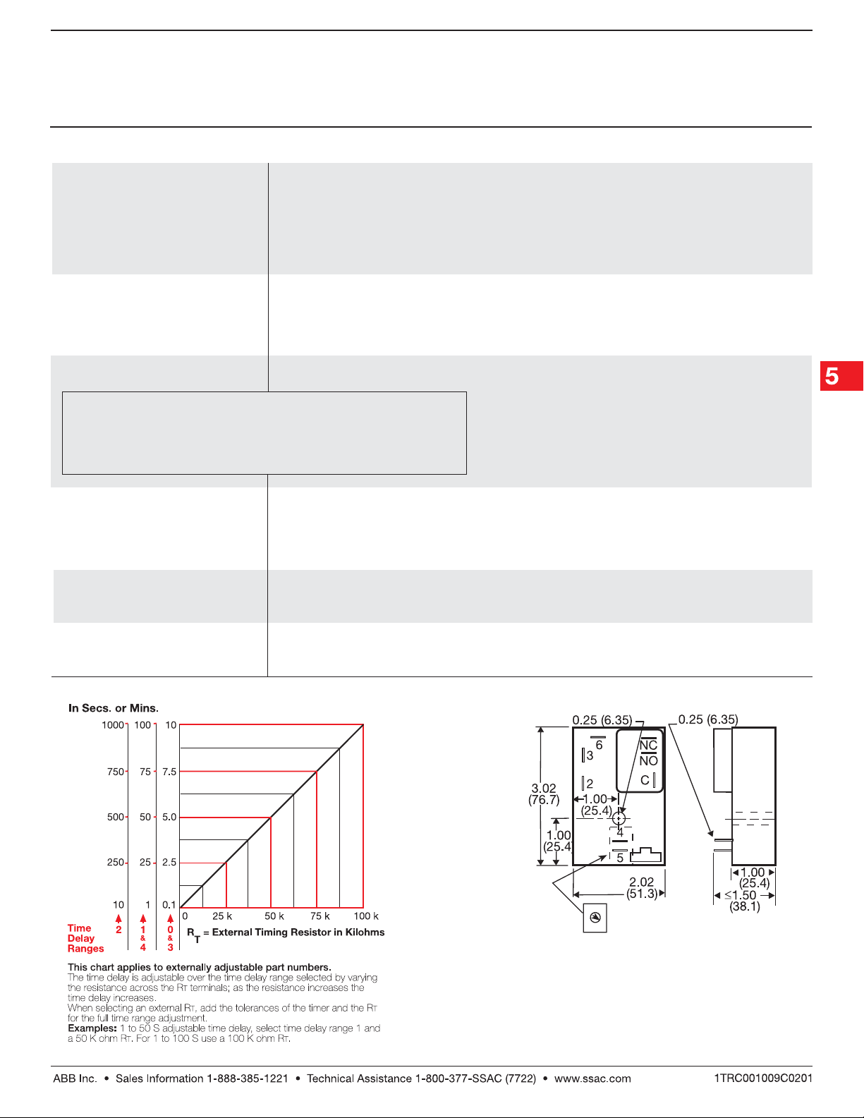
External Resistance vs Time Delay
HRDBGen 10.03.05
Low Voltage Products & Systems 5.59
Mechanical View
Onboard Adjust Detail Replaces
Terminals if Ordered
Inches (Millimeters)
 Loading...