

Page 1
Beacon TBeacon T
Beacon T
Beacon TBeacon T
ower Flasherower Flasher
ower Flasher
ower Flasherower Flasher
FS & F A Series
Solid State Flasher
DescriptionDescription
Description
DescriptionDescription
B-KON Flashers have proven their reliability through years of use on Communication Towers, Smoke Stacks,
Cooling Towers, Tall Buildings, Bridges and Utility Towers. The highest quality components are encapsulated
in a rugged plastic housing with a molded-in heat transfer plate. The flash rate, ratio, and fail-safe design meet
FAA regulations. Zero voltage switching can incr ease lamp life up to ten times. The FS155-30RF & FS165-30RF
include superior RF Filtering Circuitry for use in high RF installations; including AM Hot Towers.
Zero Voltage Switching - Up
to 10 Times Longer Lamp Life
No RFI Caused by Contacts
Closing
High Inrush Capability - Up to
200 A
RF Model for AM Hot Towers
& Other High RF Installations
Auxiliary Units for Synchronous
Flashing or Constant Line
Loading
Approvals:
(FS155 & FA155 Models Only)
OperationOperation
Operation
OperationOperation
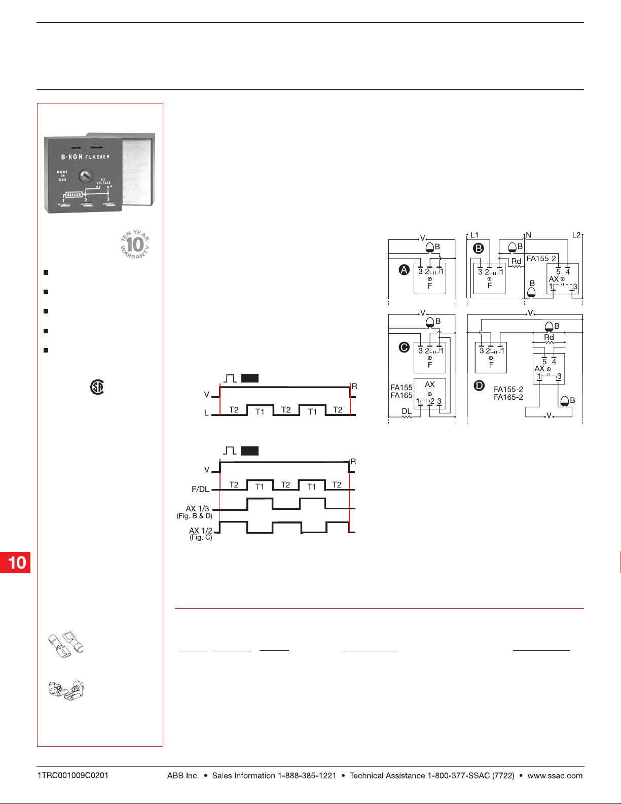
Upon application of input voltage, the T2 OFF time
begins. At the end of the OFF time, the T1 ON time
begins and the load energizes. At the end of T1, T2
begins and the load de-energizes. This cycle repeats
until voltage is removed.
Reset: Reset:
Reset: Removing input voltage resets the output
Reset: Reset:
and the sequence to T2.
FunctionFunction
Function
FunctionFunction
FS Series
Flasher (OFF First)
FA Series
Flashers & Aux. Modules
ConnectionConnection
Connection
ConnectionConnection
F = Flasher (FS155-30T, FS155-30RF,
FS165-30T , FS165-30RF)
AX = Auxiliary Unit
B = Beacon
DL = Dummy Load for Constant
Line Loading
Rd = 3.3 KΩ @ 5 W for 120 V AC
8.5 KΩ @ 5 W for 230 V AC
Dashed lines are internal connections.
AccessoriesAccessories
Accessories
AccessoriesAccessories
Female quick connect
P/N‘s:
P1015-13P1015-13
P1015-13
(AWG 10/12)
P1015-13P1015-13
P1015-64 P1015-64
P1015-64
(AWG 14/16)
P1015-64 P1015-64
P1015-14 P1015-14
P1015-14
(AWG 18/22)
P1015-14 P1015-14
Quick connect to
screw adaptor
P1015-18 P1015-18
P/N:
P1015-18
P1015-18 P1015-18
See accessory pages for
specifications.
OrOr
dering Tdering T
Or
dering T
OrOr
dering Tdering T
InputInput
Input
InputInput
120 V AC
120 V AC
230 V AC
230 V AC
120 V AC
230 V AC
120 V AC
230 V AC
V = Voltage L = Load T1 = ON Time
T2 = OFF Time R = Reset
T1 ≅ T2
ableable
able
ableable
InrushInrush
Inrush
WattageWattage
Wattage
WattageWattage
2500 W
2500 W
5000 W
5000 W
2500 W
5000 W
2500 W
5000 W
InrushInrush
200 A
200 A
200 A
200 A
200 A
200 A
200 A
200 A
For High RF Radiation locations including AM Hot Towers
Standard Flasher
For High RF Radiation locations including AM Hot Towers
Standard Flasher
Auxiliary unit for synchronous operating of additional beacons
Auxiliary unit for synchronous operating of additional beacons
Auxiliary unit to provide constant line loading
Auxiliary unit to provide constant line loading
DescriptionDescription
Description
DescriptionDescription
Part NumberPart Number
Part Number
Part NumberPart Number
FS155-30RF
FS155-30T
FS165-30RF
FS165-30T
FA155-2
FA165-2
FA155
FA165
FSFA2B01 06.0 9 . 04
Low Voltage Products & Systems10.4
Page 2
Beacon TBeacon T
Beacon T
Beacon TBeacon T
ower Flasherower Flasher
ower Flasher
ower Flasherower Flasher
FS & FA Series
Solid State Flasher
Technical DataTechnical Data
Technical Data
Technical DataTechnical Data
SpecificationsSpecifications
Specifications
SpecificationsSpecifications
Operation Single & multiple beacon flashing with auxiliary modules
Flash Rate (FS Series Only) 30 +/-10 flashes per minute
ON/OFF Ratio (FS Series Only) 50% ... 67% ON time; 33% ... 50% OFF time
InputInput
Input
InputInput
Voltage 120 or 230 V AC +/-20%
Frequency 50 ... 60 Hz
OutputOutput
Output
OutputOutput
Output Rating (Zero Voltage Switching) 2500 W at 120 V AC; 5000 W at 230 V AC
Inrush Current 200 A peak for 1 cycle of AC line
MechanicalMechanical
Mechanical
MechanicalMechanical
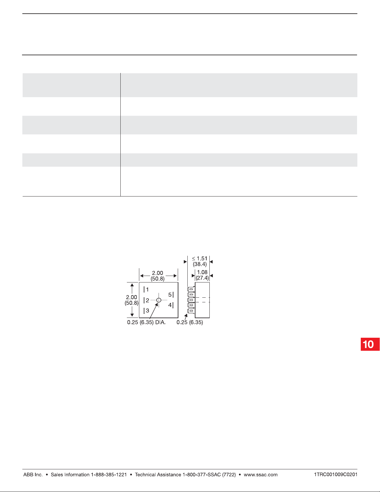
Mounting* Surface mount with one #10 (M5 x 0.8) screw
Termination 0.25 in. (6.35 mm) male quick connect terminals
ProtectionProtection
Protection
ProtectionProtection
Circuitry Encapsulated
EnvironmentalEnvironmental
Environmental
EnvironmentalEnvironmental
Operating Temperature -40°C ... +65°C
Storage Temperature -40°C ... +85°C
Humidity 95% relative, non-condensing
Weight ≅ 3.9 oz (111 g)
Note:Note:
*
Note: Must be mounted to metal surface using the included heat sink compound. The maximum mounting surface temperature is 90° C.
Note:Note:
Mechanical ViewMechanical View
Mechanical View
Mechanical ViewMechanical View
Inches (Millimeters)
Note:
Terminal # 2 is not included on FA155-2, FA165-2.
Terminal # 4 & # 5 are not included on all others.
FSFA2B01 06.0 9 . 04
Low Voltage Products & Systems 10.5
 Loading...