

Page 1

ON/OFF Recycling with
Independent Adjustment of
Both the ON and OFF
Periods
Onboard Adjust, External
Adjust, or Fixed Time Delays
0.1 s to 1000 m in 6 Ranges
+/-0.1% Repeat Accuracy
+/- 5% Factory Calibration
Available in AC or DC
Voltages
Approvals:
Recycling (Pulse Generator)Recycling (Pulse Generator)
Recycling (Pulse Generator)
Recycling (Pulse Generator)Recycling (Pulse Generator)
ESDR Series
Timing Module
DescriptionDescription
Description
DescriptionDescription
The ESDR Series offers independent time adjustment of both delay periods. Adjustment options include
onboard adjust, external adjust or factory fixed. The ESDR is recommended for air drying, automatic oiling, life
testing, chemical metering and automatic duty cycling. This series is designed for general purpose commercial
and industrial applications where a small cost effective, reliable solid state timer is required. The factory
calibration for fixed time delays is <+/- 5%. The repeat accuracy, under stable conditions, is 0.1% of the
selected time delay. This series is designed for input voltages of 12 V DC to 230 V AC in five ranges. Time
delays of 0.1 seconds to 1000 minutes are available in six ranges. The output is rated 1 A steady and 10 A
inrush. The modules are totally solid state and encapsulated to protect the electronic circuitry.
Operation (OFF Time First)Operation (OFF Time First)
Operation (OFF Time First)
Operation (ON Time First)Operation (ON Time First)
Operation (ON Time First)
Operation (ON Time First)Operation (ON Time First)
Upon application of input voltage, the output energizes
and the T1, ON time begins. At the end of the ON time,
the output de-energizes and the T2, OFF time begins.
At the end of the OFF time, the output energizes and
the cycle repeats as long as input voltage is applied.
Reset:Reset:
Reset: Removing input voltage resets the output and
Reset:Reset:
time delays, and returns the sequence to the first
delay.
FunctionFunction
Function
FunctionFunction
Recycling (ON First)
V = Voltage L = Load R = Reset
T1 = ON Time T2 = OFF Time
ConnectionConnection
Connection
ConnectionConnection
Operation (OFF Time First)Operation (OFF Time First)
Upon application of input voltage, the T2 OFF time begins. At the end of the OFF time, the output energizes
and the T1 ON time begins. At the end of the ON time,
the output de-energizes and the cycle repeats as long
as input voltage is applied.
Reset: Reset:
Reset: Removing input voltage resets the output and
Reset: Reset:
time delays, and returns the sequence to the first
delay.
FunctionFunction
Function
FunctionFunction
Recycling (OFF First)
V = Voltage L = Load R = Reset
T1 = ON Time T2 = OFF Time
OrOr
dering Tdering T
Or
dering T
OrOr
dering Tdering T
ESDR ESDR
ESDR
ESDR ESDR
SeriesSeries
Series
SeriesSeries
ESDR623B1 ESDR623B1
ESDR623B1
ESDR623B1 ESDR623B1
Fixed –
ableable
able
ableable
XX
X
XX
InputInput
Input
InputInput
1 1
–
1 - 12 V DC
1 1
2 2
–
2 - 24 V AC
2 2
3 3
–
3 - 24 V DC
3 3
4 4
–
4 - 120 V AC
4 4
6 6
–
6 - 230 V AC
6 6
Example P/N:Example P/N:
Example P/N:
Example P/N:Example P/N:
ESDR310.1SB50MN ESDR310.1SB50MN
ESDR310.1SB50MN
ESDR310.1SB50MN ESDR310.1SB50MN
Positive Switching Negative Switching
A knob is supplied for adjustment on the unit; terminals for external adjustment.
XX
X
XX
AdjustmentAdjustment
Adjustment
AdjustmentAdjustment
1 1
–
1 -
1 1
Both Times Fixed
2 2
–
2 -
Both Times Onboard Adj.
2 2
3 3
–
3 -
3 3
ON Time Onboard Adj.
OFF Time Fixed
4 4
–
4 -
ON Time Fixed
4 4
OFF Time Onboard Adj.
5 5
–
5 -
5 5
Both Times External Adj.
6 6
–
6 -
ON Time External Adj.
6 6
OFF Time Fixed
7 7
–
7 -
7 7
ON Time Fixed,
OFF Time External Adj.
8 8
–
8 -
8 8
ON Time Onboard Adj.,
OFF Time External Adj.
9 9
–
9 -
ON Time External Adj.,
9 9
OFF Time Onboard Adj.
V = Voltage
L = Load
T1 = ON Time
T2 = OFF Time
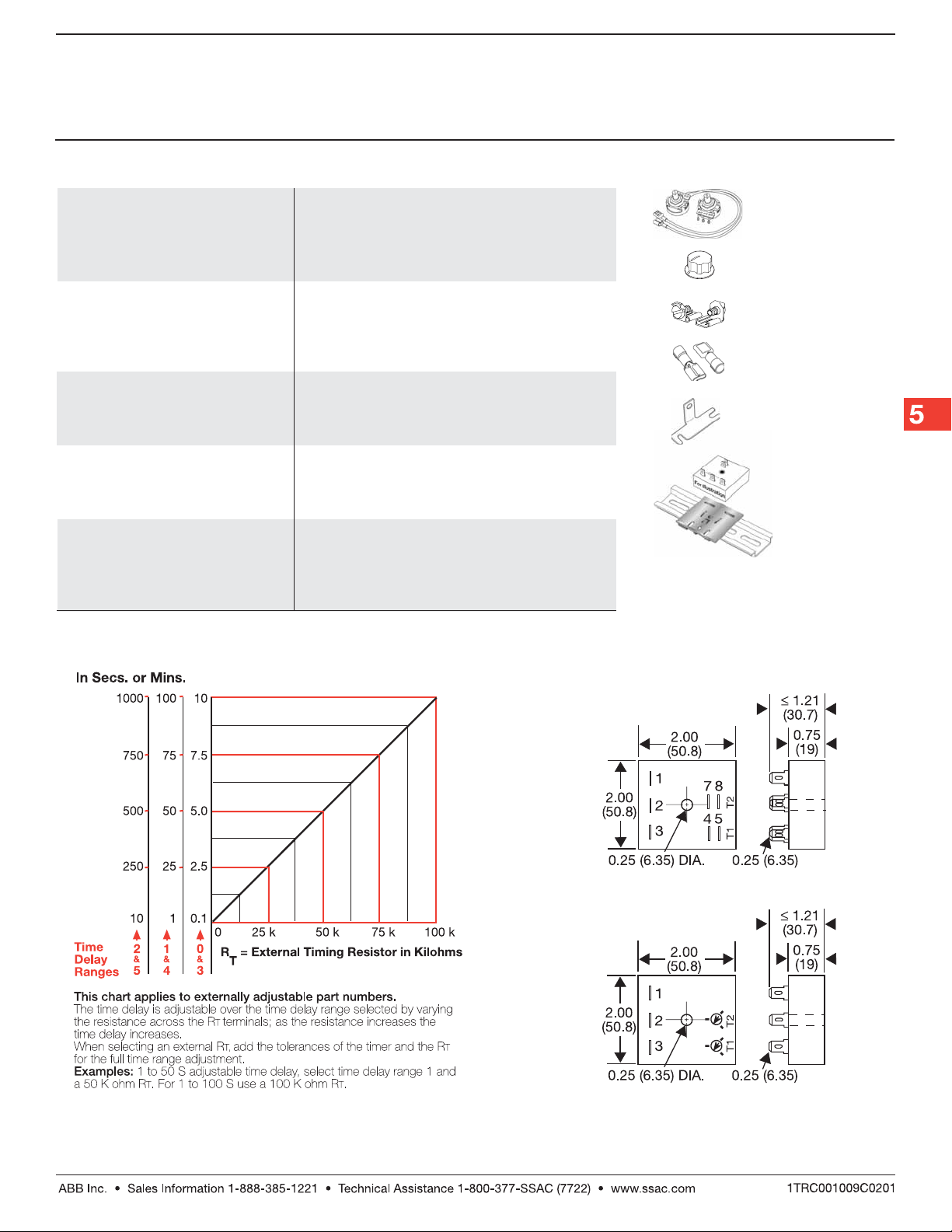
RT is used when external adjustment is ordered.
Dashed lines are internal connections.
X X
X
X X
T1 ON TimeT1 ON Time
T1 ON Time*
T1 ON TimeT1 ON Time
0 0
–
0 - 0.1 ... 10 s
0 0
1 1
–
1 - 1 ... 100 s
1 1
2 2
–
2 - 10 ... 1000 s
2 2
3 3
–
3 - 0.1 ... 10 m
3 3
4 4
–
4 - 1 ... 100 m
4 4
5 5
–
5 - 10 ... 1000 m
5 5
X X
X
X X
OperatingOperating
Operating
OperatingOperating
SequenceSequence
Sequence
SequenceSequence
A A
–
A -
A A
ON Time
First
B B
–
B -
B B
OFF Time
First
XX
X
XX
T2 OFF TimeT2 OFF Time
T2 OFF Time*
T2 OFF TimeT2 OFF Time
0 0
–
0 - 0.1 ... 10 s
0 0
1 1
–
1 - 1 ... 100 s
1 1
2 2
–
2 - 10 ... 1000 s
2 2
3 3
–
3 - 0.1 ... 10 m
3 3
4 4
–
4 - 1 ... 100 m
4 4
5 5
–
5 - 10 ... 1000 m
5 5
*If Fixed Delay is selected, insert
delay [
S S
(
S ) sec. or (
S S
Low Voltage Products & Systems5.180
0.1 0.1
1000 1000
0.1...
1000 ] followed by
0.1 0.1
1000 1000
M M
M ) min.
M M
X X
X
X X
SwitchingSwitching
Switching
SwitchingSwitching
ModeMode
Mode
ModeMode
(V DC Only)
P P
–
P - Positive
P P
N N
–
N - Negative
N N
ESDRGen 05.12.0 5
Page 2
Recycling (Pulse Generator)Recycling (Pulse Generator)
Recycling (Pulse Generator)
Recycling (Pulse Generator)Recycling (Pulse Generator)
ESDR Series
Timing Module
Technical Data Technical Data
Technical Data
Technical Data Technical Data
Time DelayTime Delay
Time Delay
Time DelayTime Delay
Range 100 ms ... 1000 m in 6 adjustable ranges or fixed
Repeat Accuracy +/-0.1% or 20 ms, whichever is greater
Tolerance (Factory Calibration) ≤ +/- 5%
Time Delay vs. Temperature & Voltage ≤ +/-2%
Reset Time ≤ 150 ms
InputInput
Input
InputInput
Voltage 12 or 24 V DC; 24, 120, or 230 V AC
Tolerance +/-20%
Power Consumption AC ≤ 2 VA; DC ≤ 1 W
Line Frequency 50 ... 60 Hz
DC Ripple ≤ 10%
OutputOutput
Output
OutputOutput
Type Solid state
Maximum Load Current 1 A steady state , 10 A inrush at 60°C
OFF State Leakage Current AC ≅ 5 mA at 230 V AC; DC ≅ 1 mA
Voltage Drop AC ≅ 2.5 V at 1 A; DC ≅ 1 V at 1 A
ProtectionProtection
Protection
ProtectionProtection
Circuitry Encapsulated
Dielectric Breakdown ≥ 2000 V RMS terminals to mounting surface
Insulation Resistance ≥ 100 MΩ
Polarity DC units are reverse polarity protected
MechanicalMechanical
Mechanical
MechanicalMechanical
Mounting Surface mount with one #10 (M5 x 0.8) screw
Termination 0.25 in. (6.35 mm) male quick connect terminals
Operating/Storage Temperature -40°C ... +75°C / -40°C ... +85°C
Humidity 95% relative, non-condensing
Weight ≅ 2.4 oz (68 g)
AccessoriesAccessories
Accessories
AccessoriesAccessories
BB
B
BB
External adjust
potentiometer
P/Ns:
AA
A
AA
P1004-95P1004-95
P1004-95
P1004-95P1004-95
P1004-95-XP1004-95-X
P1004-95-X
P1004-95-XP1004-95-X
Versa-knob
P/N:
Quick connect to
screw adaptor
P/N:
Female quick connect
P/N:
P1015-64 P1015-64
P1015-64
P1015-64 P1015-64
(fig A)
(fig B)
P0700-7 P0700-7
P0700-7
P0700-7 P0700-7
P1015-18 P1015-18
P1015-18
P1015-18 P1015-18
(AWG 14/16)
Mounting bracket
P1023-6 P1023-6
P/N:
P1023-6
P1023-6 P1023-6
DIN rail P/Ns:
017322005 017322005
017322005 (Steel)
017322005 017322005
C103PM C103PM
C103PM (Al)
C103PM C103PM
←
→
DIN rail adaptor
P1023-20 P1023-20
P/N:
P1023-20
P1023-20 P1023-20
See accessory pages for specifications.
External Resistance vs Time DelayExternal Resistance vs Time Delay
External Resistance vs Time Delay
External Resistance vs Time DelayExternal Resistance vs Time Delay
ESDRGen 05.12.0 5
Mechanical ViewMechanical View
Mechanical View
Mechanical ViewMechanical View
Fixed & External AdjustFixed & External Adjust
Fixed & External Adjust
Fixed & External AdjustFixed & External Adjust
Onboard AdjustOnboard Adjust
Onboard Adjust
Onboard AdjustOnboard Adjust
Low Voltage Products & Systems
Inches (Millimeters)
5.181
 Loading...