

Recycling (Flasher)Recycling (Flasher)
Recycling (Flasher)
Recycling (Flasher)Recycling (Flasher)
ERD3 Econo-Timer
Time Delay Relay
DescriptionDescription
Description
DescriptionDescription
Econo-Timers are a combination of digital electronics and a reliable electromechanical relay. DPDT relay
output for relay logic circuits, and isolation of input to output voltages. Cost effective for OEM applications such
as duty cycling, drying, washing, signaling, and flashing.
Knob, External Adjust or
Factory Fixed
Delays From 0.1 s ... 1000 m
+/-0.5% Repeat Accuracy
Encapsulated Digital Circuitry
10 A, Isolated, DPDT Output
Contacts
Approvals:
AccessoriesAccessories
Accessories
AccessoriesAccessories
BB
B
BB
External adjust
potentiometer
AA
A
AA
P/Ns:
P1004-16 P1004-16
P1004-16 (fig A)
P1004-16 P1004-16
P1004-16-X P1004-16-X
P1004-16-X (fig B)
P1004-16-X P1004-16-X
Female quick
connect
P/N:
P1015-64 P1015-64
P1015-64
P1015-64 P1015-64
Quick connect to
screw adaptor
P1015-18 P1015-18
P/N:
P1015-18
P1015-18 P1015-18
Versa-knob
P0700-7 P0700-7
P/N:
P0700-7
P0700-7 P0700-7
(AWG 14/16)
See accessory pages for
specifications.
OperationOperation
Operation
OperationOperation
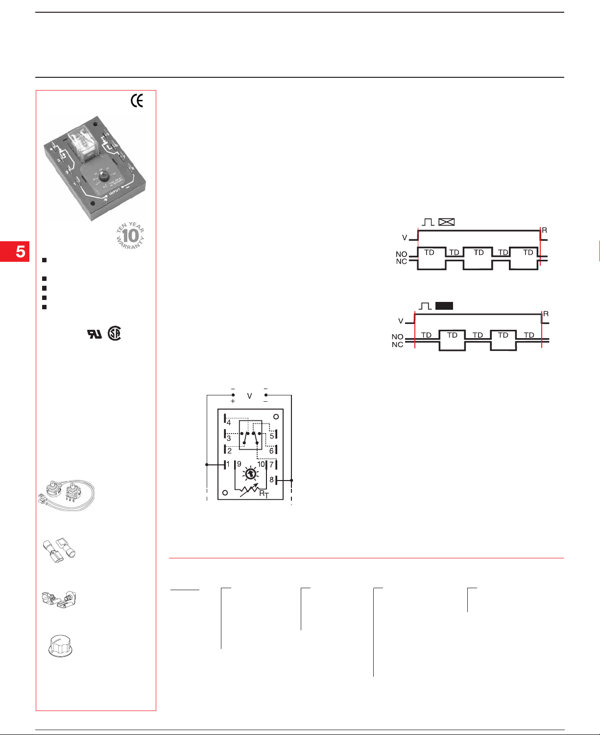
Upon application of input voltage, the output energizes
and the ON time begins. At the end of the ON time, the
output de-energizes and the OFF time begins. At the
end of the OFF time, the output energizes and the
cycle repeats as long as input voltage is applied. The
OFF time may be the first delay in some recycling
timers.
Reset:Reset:
Reset: Removing input voltage resets the output
Reset:Reset:
and time delays, and returns the sequence to the first
delay.
ConnectionConnection
Connection
ConnectionConnection
A knob, or terminals 9 & 10 are only included on
adjustable units. Relay contacts are isolated.
Dashed lines are internal connections.
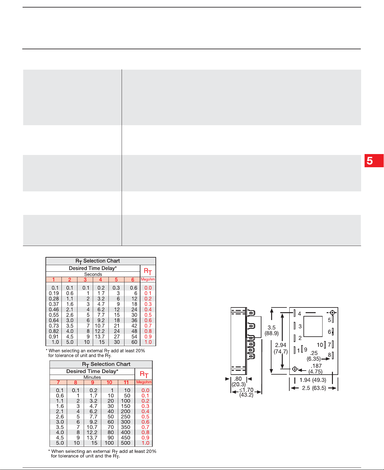
R
is used when external adjustment is ordered.
T
OrOr
dering Tdering T
Or
dering T
OrOr
dering Tdering T
ERD3 ERD3
ERD3
ERD3 ERD3
SeriesSeries
Series
SeriesSeries
Example P/N:Example P/N:
Example P/N:
Example P/N:Example P/N:
ableable
able
ableable
X X
X
X X
InputInput
Input
InputInput
11
–
1 - 12 V DC
11
22
–
2 - 24 V AC
22
3 3
–
3 - 24 V DC
3 3
44
–
4 - 120 V AC
44
55
–
5 - 120 V DC
55
66
–
6 - 230 V AC
66
ERD3426A ERD3426A
ERD3426A Fixed –
ERD3426A ERD3426A
X X
X
X X
AdjustmentAdjustment
Adjustment
AdjustmentAdjustment
11
–
1 - Fixed
11
2 2
–
2 - Knob on
2 2
Unit
33
–
3 - External
33
Adjust
ERD3410.1SAERD3410.1SA
ERD3410.1SA
ERD3410.1SAERD3410.1SA
FunctionFunction
Function
FunctionFunction
Recycling (ON First)
Recycling (OFF First)
V = Voltage R = Reset TD = Time Delay
NO = Normally Open NC = Normally Closed
X X
X X
X
X X
Time DelayTime Delay
Time Delay *
Time DelayTime Delay
1 1
–
1 - 0.1 ... 1 s
1 1
2 2
–
2 - 0.1 ... 5 s
2 2
3 3
–
3 - 0.1 ... 10 s
3 3
4 4
–
4 - 0.2 ... 15 s
4 4
5 5
–
5 - 0.3 ... 30 s
5 5
66
–
6 - 0.6 ... 60 s
66
77
–
7 - 0.1 ... 5 m
77
88
–
8 - 0.1 ... 10 m
88
99
–
9 - 0.2 ... 15 m
99
1010
–
10 - 1 ... 100 m
1010
1111
–
11 - 10 ... 500 m
1111
X
X X
Operating SequenceOperating Sequence
Operating Sequence
Operating SequenceOperating Sequence
A A
–
A - ON Time First
A A
BB
–
B - OFF Time First
BB
*If Fixed Delay is selected,
insert delay [
SS
by (
S) sec. or (
SS
0.10.1
0.1...
0.10.1
10001000
1000] followed
10001000
MM
M) Min.
MM
ERD32B01 07.01.04
Low Voltage Products & Systems5.172
Recycling (Flasher)Recycling (Flasher)
Recycling (Flasher)
Recycling (Flasher)Recycling (Flasher)
ERD3 Econo-Timer
Time Delay Relay
Technical Data Technical Data
Technical Data
Technical Data Technical Data
Time DelayTime Delay
Time Delay
Time DelayTime Delay
Type Digital integrated circuitry
Range 100 ms ... 500 m in 11 adjustable ranges
Adjustment Knob, external adjust, or fixed
Repeat Accuracy +/-0.5%
Tolerance (Factory Calibration) ≤ +/-10%
Reset Time ≤ 150 ms
Time Delay vs. Temperature & Voltage ≤ +/-2%
InputInput
Input
InputInput
Voltage 12, 24, or 120 V DC; 24, 120, or 230 V AC
Tolerance 12 V DC & 24 V DC/AC -15% ... +20%
120 V AC/DC & 230 V AC -20% ... +10%
Line Frequency 50 ... 60 Hz
OutputOutput
Output
OutputOutput
Type Isolated relay contacts
Form Double pole double throw (DPDT)
Rating 10 A resistive at 120/240 V AC & 28 V DC
Life Mechanical--1 x 10⁷; Electrical--1 x 10
ProtectionProtection
Protection
ProtectionProtection
Isolation Voltage ≥ 1500 V RMS input to output
Insulation Resistance ≥ 100 MΩ
Polarity DC units are reverse polarity protected
MechanicalMechanical
Mechanical
MechanicalMechanical
Mounting Surface mount with two #6 (M3.5 x 0.6) screws
Termination 0.25 in. (6.35 mm) male quick connect terminals
Operating/Storage Temperature -40°C ... +65°C / -40°C ... +85°C
Weight ≅ 5.7 oz (162 g)
100 ms ... 1000 m fixed
1/3 hp at 120/240 V AC
6
Mechanical View Mechanical View
Mechanical View
Mechanical View Mechanical View
Inches (Millimeters)
ERD32B01 07.01.04
Low Voltage Products & Systems 5.173
 Loading...