

Page 1
Overcurrent & Undercurrent
(Window Current) Sensing
Adjustable Overcurrent &
Undercurrent Trip Points
Current Sensor is Included
10 A SPDT Isolated Output
Contacts
LED Indicators
Approvals:
Selector Switch
ON OFF
SW1
SW2
SW3
Not Used
Latched
Zero I
Output
Normally
Energized
Window Current Sensor
ECSW Series
Current Sensor
Description
The ECSW Series of single phase, AC window current sensors includes adjustable overcurrent and undercurrent
trip points. Detects locked rotor, a jam, loss of load, an open heater or lamp load, a broken belt, or loss of
suction. LED's aid in trip point adjustment and provide fault indication. The built-in toroidal sensor eliminates
the need for an external current transformer . The output can be electrically latched after a fault, or automatically
reset. Remote resetting of a latched output by removing input voltage. The unit includes switch selectable zero
current detection and normally de-energized or energized output operation. Time delays are included to
improve operation and eliminate nuisance tripping.
Operation
When the input voltage is applied, sensing delay on startup begins and the output transfers (if normally
energized is selected). Upon completion of the startup delay, sensing of the monitored current begins. As long
as current is above undercurrent trip point and below the overcurrent trip point (inside the window), the output
relay remains in its normal operating condition and both red LED's are OFF. The green LED glows when the
output is energized. If current varies outside the window, the associated red LED glows, and the trip delay
begins. If the current remains outside the window for the full trip delay, the relay transfers to fault condition
state. If the current returns to normal levels (inside the window) during the trip delay, the red LED goes OFF, the
trip delay is reset, and the output remains in the normal condition.
Reset: Remove input voltage or open latch switch. If zero current detection is selected, the unit will reset as
soon as zero current is detected.
Operation With Zero Current Detection Enabled: If the current decreases to zero within the trip delay period,
then zero current is viewed as an acceptable current level. The unit's output remains in its normal operating
state. This allows the monitored load to cycle ON and OFF without nuisance tripping the ECSW. Zero current
is defined as current flow of less than 250 milliamp-turns. Note: When zero current detect is selected, the
latching operation of switch SW2 is canceled; the output will not latch after a fault trip.
Notes on Operation:
1) There is no hysteresis on the trip points. The overcurrent and undercurrent trip points should be adjusted
to provide adequate protection against short cycling.
2) If the upper set point is set below the lower set point, both red LED's will glow indicating a setting error.
3) If zero current detection is selected (SW2 ON), and the system is wired to disconnect the monitored load,
the system may short cycle. After the unit trips, the load de-energizes, and zero current is detected. The
ECSW resets, and the load energizes again immediately and may be short cycled.
4) The sensing delay on start up only occurs when input voltage is applied. When zero current detection is
selected, the trip delay must be longer than the duration of the inrush current or the unit will trip on the
inrush current.
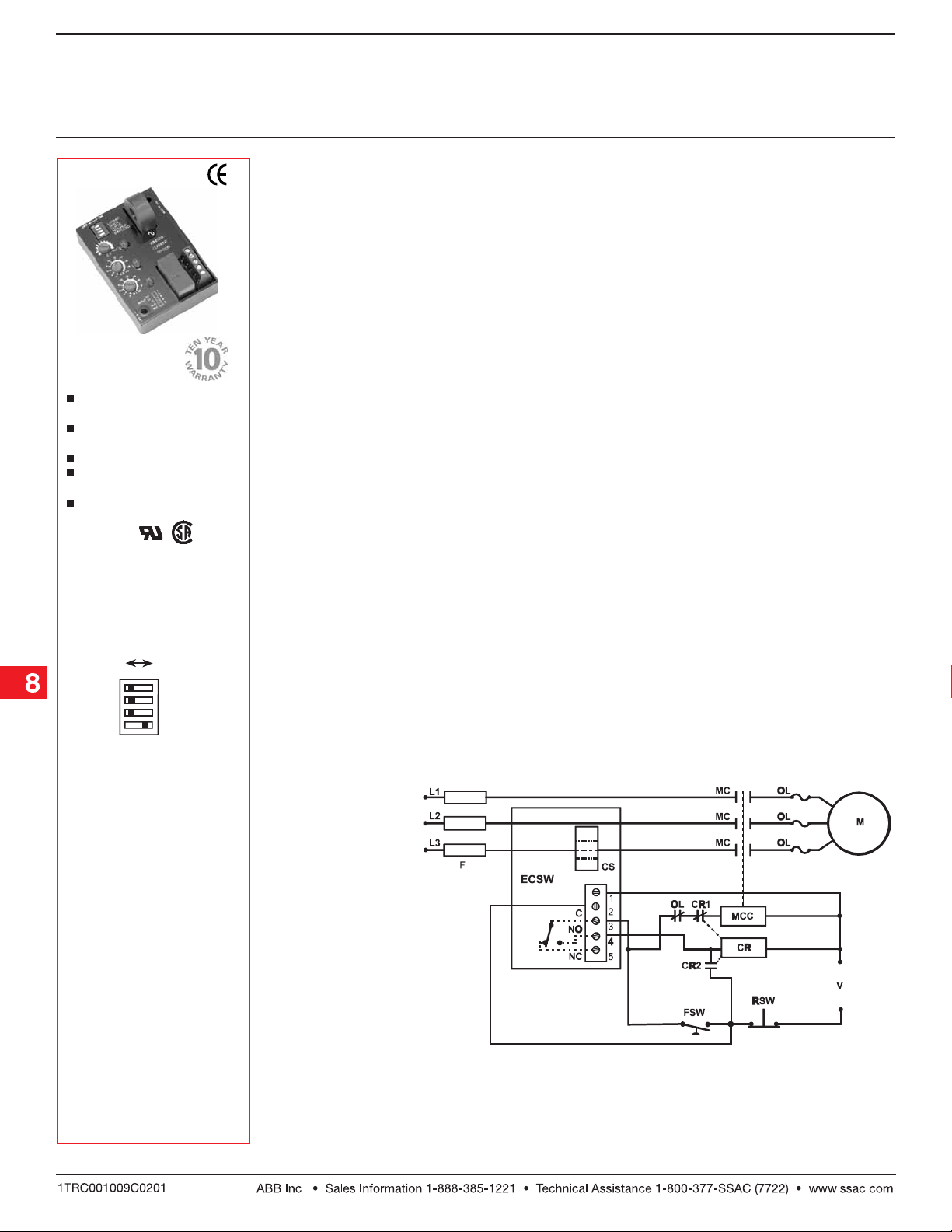
Typical Pump or Fan Protection Circuit Operation
Window Current Sensing: With the ECSW connected as shown in the diagram, a load may be monitored
and controlled for over and under current. The ECSW Series' on board CT (CS) may be placed on the line or
load side of the contactor. The ECSW selection switches are set for zero current sensing (see Selector Switch
SW2) and the output selection is normally de-energized (see Selector Switch SW3). The input voltage (V) is
applied to the ECSW continually. As the control switch (FSW) is closed, the input voltage (V) is applied to the
motor contactor coil (MCC), and the motor (M) energizes. As long as the current remains below the overcurrent
and above the undercurrent trip points, the ECSW's output contacts remain de-energized. If the load current
should rise above or fall below a trip point, for the full trip delay, the normally open (NO) contact will close,
energizing the control relay (CR) coil. The CR normally closed contact (CR1) opens and the MCC de-energizes
and CR latches on through its normally open contacts (CR2). Reset is accomplished by momentarily opening
the normally closed reset switch (RSW).
Connection
Mode Selection Switches
SW1 = Latched or Auto reset
selector
OFF - Automatic reset after a
fault
ON - Output relay latches
after a fault trips the
unit
SW2 = Zero current detection (below 250 mA)
OFF- Zero current detection
disabled
ON- Zero current detection
enabled
SW3 = Output during normal
operation
OFF- Output relay de-energized
ON - Output relay energized
Note: If the current falls to
zero within the trip delay, the
ECSW remains de-energized.
The sensing delay on startup
occurs when input voltage is
applied therefore trip delay
must be longer than the
duration of the motor's inrush
current. The external latching
relay CR2 is required in this
system to prevent rapid
cycling. A timer can be added
to provide an automatic reset.
MC = Motor Contactor M = Motor F = Fuses
OL = Overload RSW = Reset Switch
FSW = Fan or Float Switch CR = Control Relay
CS = Current Sensor MCC = Motor Contactor Coil
Note: The output is normally de-energized.
Low Voltage Products & Systems8.6
+
-
ECSW2B01 12.12. 05
Page 2

Window Current Sensor
ECSW Series
Current Sensor
Technical Data
Sensor
Type Toroid, through hole wiring for up to #4 AWG (21.1 mm2) THHN wire
Mo de Over and under current trip points (window current sensing)
Trip Point Range 0.5 ... 50 A in 3 adjustable ranges
Tolerance Guaranteed range
Maximum Allowable Current Steady - 50 A turns; Inrush - 300 A turns for 10 s
Trip Point vs. Temperature & Voltage +/- 5%
Response Time ≤ 75 ms
Frequency 45 ... 500 Hz
Type of Detection Peak detection
Zero Current Detection < 250 mA turns typical
Time Delay
Range 0.15 ... 50 s in 2 adjustable ranges or 0.08 ... 50 s fixed
Tolerance Adjustable: guaranteed range; Fixed: +/-10%
Sensing Delay On Start Up Fixed ≅ 0.1 ... 6 s in 1 s increments
Tolerance +40% -0%
Delay vs. Temperature & Voltage +/-1 5%
Input
Voltage 24, 120, or 230 V AC; 12 or 24 V DC
Tolerance 12 V DC & 24 V DC/AC -15% ... +20%
120 & 230 V AC -20% ... +10%
AC Line Frequency 50 ... 60 Hz
Output
Type Electromechanical relay
Mode: Switch selectable ON - Energized during normal operation, de-energized after a fault
OFF - De-energized during normal operation, energizes during a fault
Form Isolated, SPDT
Rating 10 A resistive at 240 V AC; 1/4 hp at 125 V AC;
Life Mechanical: 1 x 10⁶; Electrical: 1 x 10
Latch Type Electrical
Reset Remove input voltage
Function Switch selectable latching function
Protection
Surge IEEE C62.41-1991 Level A
Circuitry Encapsulated
Isolation Voltage ≥ 2500 V RMS input to output
Insulation Resistance ≥ 100
Mechanical
Mounting Surface mount with two #6 (M3.5 x 0.6) screws
Termination 0.197 in. (5 mm) terminal blocks for up to
Environmental
Operating Temperature -40° C ... +60° C
Storage Temperature -40° C ... +85° C
Humidity 95% relative, non-condensing
Weight ≅ 6.4 oz (181 g)
1/2 hp at 250 V AC
MΩ
#12 (3.2 mm2) AWG wire
5
Connection
V = Voltage W = Monitored Wire
∆T = Adjustable Trip Delay
I> = Adjustable Overcurrent
I< = Adjustable Undercurrent
Mechanical View
Inches (Millimeters)
Ordering Table
X ECSW
Series Input
–1 - 12 V DC
–2 - 24 V AC
–3 - 24 V DC
–4 - 120 V AC
–6 - 230 V AC
ECSW2B01 12.12. 05
Example P/N: ECSW4LBCT Fixed - ECSW4HF10DT
Low Voltage Products & Systems 8.7
X
Trip Point Range
Adjustable Ranges
–L - 0.5 ... 5 A
–M - 2 ... 20 A
–H - 5 ... 50 A
Trip Delay
–A - Adjustable 0.15 ... 7 s
–B - Adjustable 0.5 ... 50 s
–F - Fixed*
Sensing Delay
on Start Up
–B - 0.1 s
–C - 1 s
–D - 2 s
–E - 3 s
–F - 4 s
–G - 5 s
–H - 6 s
*If Fixed Delay is selected, insert delay
[0.08 ... 50] in seconds. 0.1 ... 2 s in 0.1 s
increments; 2 ... 50 s in 1 s increments
XXX
Connection
–T - Terminal Blocks
 Loading...