

Page 1
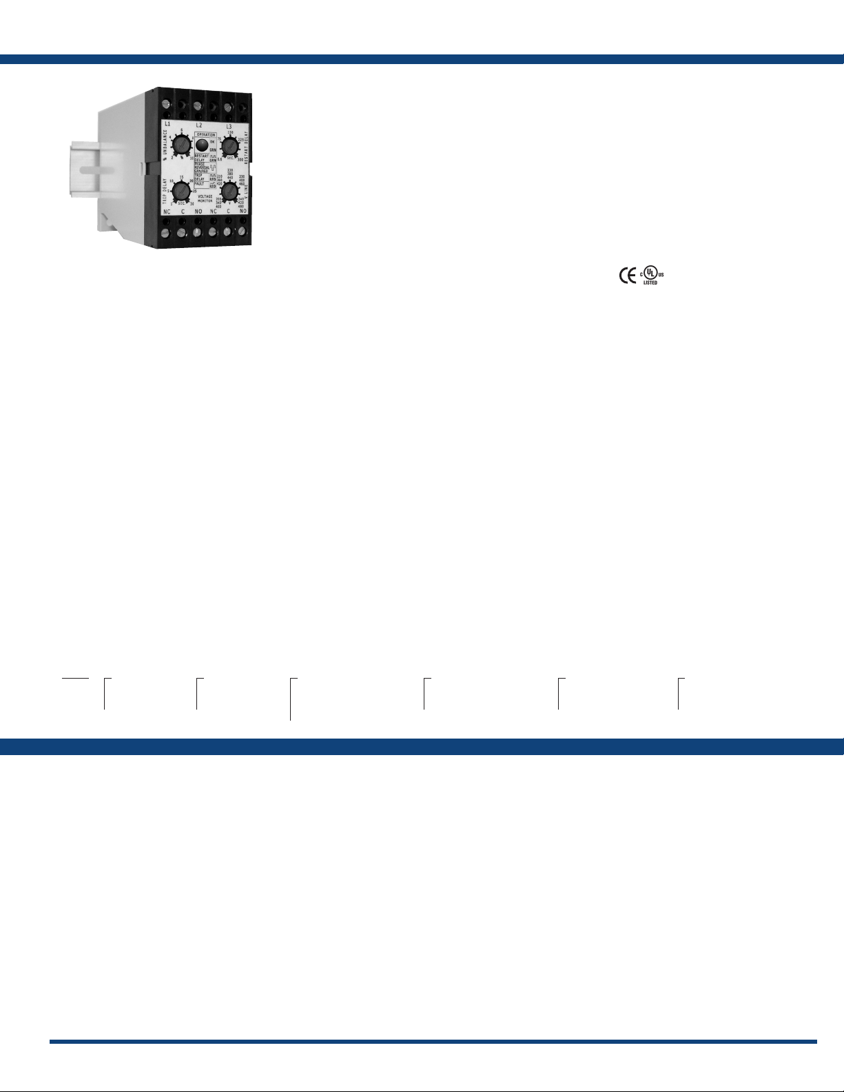
DLMU SeriesVoltage Monitors
The DLMU Series is a universal voltage, 3-phase
voltage monitor. It continuously measures
the voltage of each of the three phases with
microcontroller accuracy and compares the value
to preset trip points. It separately senses phase
reversal and loss; over, under and unbalanced
voltages; and over or under frequency. Protection
is assured during periods of large average voltage
uctuations or when regenerated voltages are
present. The unit trips within 200ms when phase
loss is detected. Adjustable time delays are
included to prevent nuisance tripping and short
cycling of sensitive equipment. The isolated,
10A, SPDT and 2A alarm output relay contacts
trip when a phase voltage exceeds the trip limits
for the trip delay. Nominal line voltage, voltage
unbalance, and time delays are knob adjustable.
Features:
• Protects against phase & reversal; over,
under & unbalanced voltages; & over &
under frequency
• 35mm DIN rail or surface mounting
• Isolated, 10A, relay contacts
• Isolated, 2A, NO or NC, SPST relay contact
• LED indicates relay, faults, & time delays
• Universal line voltage 240 to 480VAC
• 600VAC version available
• 3-wire connection for delta or wye systems
• ASME A17.1 rule 210.6
• NEMA MG1 14:30, 14:35
• IEEE C62.41-1991 Level B
Approvals:
The phase loss setpoint and the acceptable
f r e q u e n c y r a n g e a r e x e d . B o t h d e l t a a n d w y e
systems can be monitored; no connection to
neutral is required.
For more information see:
Appendix B, page 166, Figure 16 for dimensional drawing.
Operation
Upon application of line voltage, the output is de-energized and the restart delay begins. If all the 3-phase voltages are
within the acceptable range, the output energizes at the end of the restart delay. The microcontroller circuitry automatically
senses the voltage range, and selects the correct operating frequency (50 or 60Hz). The over and undervoltage trip points
are set automatically. When the measured value of any phase voltage exceeds the acceptable range limits (lower or upper)
the trip delay begins. At the end of the trip delay the output relay de-energizes. If the phase voltage returns to an acceptable
value before the trip delay expires, the trip delay is reset and the output remains energized. Under, over, and unbalanced
voltages plus over or under frequency must be sensed for the complete trip delay before the unit trips. The unit trips in
200ms when phase loss or reversal are sensed. The unit will not energize if a fault is sensed as the line voltage is applied.
Reset: Reset is automatic upon correction of the voltage or frequency fault or phase sequence.
Restart Delay Options:
L= Lockout or minimum OFF time. The restart delay begins when the output trips. The unit cannot be re-energized until the restart delay is complete. This provides a minimum off time or
lockout time to allow equipment sensitive to short cycling, time to reset. If the fault is corrected after the restart delay is complete the output energizes immediately. The restart delay also
occurs when line voltage is applied/reapplied.
R= Restart Delay on fault correction. The restart delay begins when line voltage is reapplied or when a voltage fault is corrected. This option is normally selected when staggered restarting
of multiple motors on a power system is required.
N= No Restart Delay. 0.6 second initialization delay on application of line voltage applies.
Restart Notes:
All restart options remain reset when the following conditions are detected:
1.) Phase loss (phase unbalance greater than 25%) 2.) Average line voltage less than 120VAC 3.) Phase reversal
The restart delay begins when the condition is corrected.
LED Operation
The LED ashes green during the restart delay, then glows green when the output energizes. It ashes red during the trip delay then glows red when the output de-energizes. It ashes red/
green if phase reversal is sensed If a fault is sensed during the restart delay, the LED will glow red during that portion or the full restart delay.
Order Table:
DLM
X
Line Voltage
─U - 200-480VAC
─H - 500-600VAC
X
Output
─B - SPDT & NO
─C - SPDT & NC
Appendix C, page 168, Figure 11 for connection diagram.
X
Restart Function
─L - Lockout, min off time
─R - Staggered restarting
─N - No Restart Delay
X
Voltage Unbalance
─A - Adjustable 2-10%
─Fixed - Specify unbalance
2-10% in 1% increments
using two digits [04]
Auxiliary Products:
• 3-phase fuse block/disconnect:
P/N: FH3P
• 2 Amp fuse: P/N: P0600-11
• DIN rail: P/N: C103PM (Al)
Available Models:
DLMHBRAAA
DLMUBNAAN
DLMUBRAAA
If desired part number is not listed, please call us to
see if it is technically possible to build.
X
Trip Delay
─A - Adjustable 1-30s
─Fixed - Specify delay
1-30s in 1s increments,
using two digits [20]
X
Restart Delay
─A* - Adjustable 0.6-300s
─N - No Restart Delay
* Selection “A” is only available
for L or R Restart Functions
Specications
Line Voltage
Type ........................3-phase delta or wye with no connection to neutral
Operating Voltage
200-480VAC Range Voltage Adj.Range Line Frequency Line Voltage Max.
240 200-240VAC 50/60Hz
380 340-420VAC 50Hz
480 400-480VAC 60Hz 550VAC
600VAC 600 500-600VAC 50/60Hz 600VAC
AC Line Frequency ............50/60 Hz automatically detected
Phase Loss ....................≥ 25% unbalance
Response Time ..............≤200ms
Undervoltage & Voltage Unbalance
Type .......................Voltage detection with delayed trip & automatic reset
Overvoltage TripVoltage ......109 - 113% of the adjusted line voltage
Reset Voltage ....≅ -3% of the trip voltage
Undervoltage Trip Voltage .....88 - 92% of the adjusted line voltage
Reset Voltage ....≅ +3% of the trip voltage
Voltage Unbalance ............Adjustable 2 - 10% or specify xed unbalance of 2 - 10%
in 1% increments
Reset on balance ...≅ -0.7% unbalance
Trip Delay Active On .........O v e r/ un d e r v o l t ag e, v o l t a g e un ba l a n c e , o ve r/ u n d e r f r eq ue n c y
Range .............Adjustable from 1 - 30s or specify xed delay 1 - 30s in 1s
increments
Tolerance ..........± 15%
www.ssac.com • 800-843-8848 • fax: 605-348-5685
Restart Delay Range ............Adjustable from 0.6 - 300s; if no restart delay is
selected a 0.6s initialization delay applies
Tolerance .........± 15%
Over/Under Frequency ..........±4%; Reset ±3%; 50/60 Hz
Phase Sequence .................A, B, C, L1, L2, L3
Response Time
Reset ...........................Automatic
Output
Type ..........................Isolated Electromechanical Relay
Rating .........................10A resistive @ 240VAC; 8A resistive @ 277VAC;
NO-1/4 hp @ 120VAC; 1/3 hp @ 240VAC
Life ............................ Mechanical - 1 x 10⁶; Electrical - 1 x 30
Protection
Surge ..........................IEEE C62.41-1991 Level B
Isolation Voltage ................≥ 2500V RMS input to output
Mechanical
Mounting ......................Surface mount with 2 #8 (M4 x 0.7) screw or snap on
35mm DIN Rail
Note: 0.25 in.(6.35 mm) spacing between units or other devices is required
Dimensions .....................4.33 x 2.95 x 1.97 in. (110 x 75 x 50 mm)
Termination ....................Screw terminals with captive wire clamps for up to
#14 AWG (2.5 mm2) wire
Environmental
Operating / Storage Temperature . -40° to 60°C / -40° to 85°C
Humidity .......................95% relative, non-condensing
Weight .........................≅ 8.6 oz (244 g)
-Phase Reversal & Phase Loss
. . . . ≤200 ms
3
111
Page 2
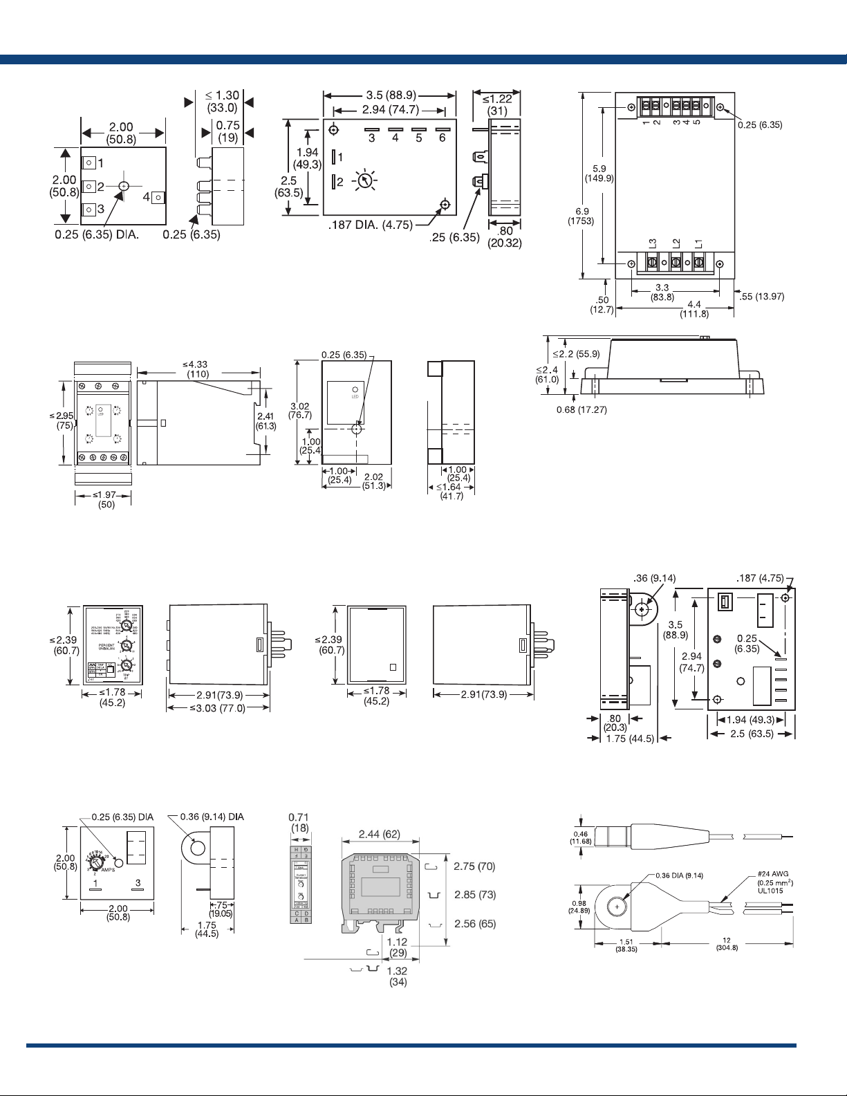
Appendix B - Dimensional Drawings
FIGURE 13 FIGURE 14 FIGURE 15
AF
SC3; SC4; SQ
FIGURE 16 FIGURE 17
RC
RC
DLMU
FIGURE 18
FB9L; HLMU; SCR9L
FIGURE 19
WVM
FIGURE 20
PLMU
FIGURE 21
TCS; TCSA
166
LLC4; LLC6; PLS
ECS; ECSW
FIGURE 22 FIGURE 23
LCS
DCSA
inches (millimeters)
www.ssac.com • 800-843-8848 • fax: 605-348-5685
(ECS has spade connectors and
ECSW has terminal board)
Page 3

Appendix C - Connection Diagrams
L1 N/L2
FIGURE 1 - FSU1000 Series
L1 N/L2
S1 = Optional low current switch
V = Voltage
L = Load
FIGURE 5 - FS300 Series
V = Voltage
L = Load
Note: Load may be in positive side.
FIGURE 2 - FS100 Series
L1 N
V = Voltage
L = Load
R = Red Wire
B = Black Wire
FIGURE 6 - FS400 Series
L1 N/L2
V = Voltage
L = Load
R = Red Wire
B = Black Wire
W= White Wire
FIGURE 3 - FS100 Series FIGURE 4 - FS200 Series
L1 N/L2
V = Voltage
V = Voltage
L = Load
FIGURE 7 - AF Series
L1 N/L2
V = Voltage
L = Load
L = Load
FIGURE 8 - FS500 Series
L1 N/L2
V = Voltage
FIGURE 11 - DLMU Series
FIGURE 9 - SC3/SC4 Series
SC4 shown;
for SC3, terminal 6 & load L4 are eliminated.
FIGURE 12 - HLMU Series
Note: Relay contacts are
L1, L2, L3 = Line Voltage Input
NO = Normally Open Contact
NC = Normally Closed Contact
C = Common, Transfer Contact
CAUTION: 2 amp max. fast acting fuses are
recommended to protect the equipment‘s
wiring. They are not required to protect the
HLMU.
isolated, 277VAC max.
FIGURE 10 - WVM Series
F = Fuses
NO = Normally Open
NC = Normally Closed
RS =
Optional Remote Reset Switch
Relay contacts are isolated.
CAUTION:
2 amp max fast acting fuses must
be installed externally in series
with each input. (3)
FIGURE 13 PLMU/PLM/PLR/PLS Series
F = Fuses
ØA = Phase A = L1
ØB = Phase B = L2
ØC = Phase C = L3
NO = Normally Open
NC = Normally Closed
2A fast acting fuses
recommended for safety (not
required)
Relay contacts are isolated.
!
L1, L2, L3 = Line Voltage Input
NO = Normally Open Contact
NC = Normally Closed Contact
C = Common, Transfer Contact
CAUTION: 2 amp max. fast acting
fuses are recommended to protect
the equipment‘s wiring. They are not
required to protect the DLMU.
! = Select alarm contact connection as N.O. or
N.C. when ordering; N.O. Shown.
FIGURE 14 TVM/TVW Series
L1 = Phase A
L2 = Phase B
L3 = Phase C
NO = Normally Open
NC = Normally Closed
C = Common, Transfer Contact
Relay contacts are isolated.
F = 2A Fast acting fuses are recommended,
but not required
168
www.ssac.com • 800-843-8848 • fax: 605-348-5685
 Loading...