

Page 1
Knob Adjustable Universal Timer
ASQU/ASTU MicroTime
Timing Module
Description
The ASQU/ASTU Series of 17.5 mm, knob adjustable, universal solid state timers offer multiple functions,
voltages, and time delay ranges. Choose one of 5 functions and 4 time delay ranges via 4 selection switches
located on top of the unit. Adjustment through the time range is accomplished by an onboard knob.
17.5 mm Package for High
Rail Density
Microprocessor Controlled
with +/-1% Repeat Accuracy
Multimode: 5 Selectable
Functions
Multirange: Knob Adjustable
from 0.1 s ... 100 m
Multivoltage: 24 ... 240 V AC
or 9 ... 110 V DC
0.7 A Steady, 10 A Inrush
Rated Solid State Output
Approvals:
Adjustment
10...1000s
1...100m
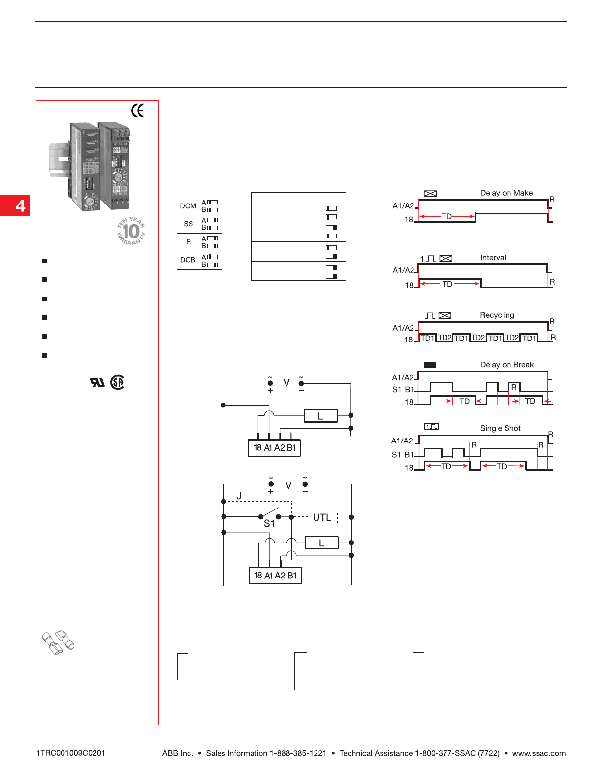
DOM = Delay On Make
SS = Single Shot/Interval
R = Recycling
DOB = Delay On Break
Connection
Delay on Make & Recycling
R M S
0.1...10s
1...100s
X1s
X10s
X100s
X10m
R = Range
M = Multiplier
S = Setting
Function
C
E
D
F
C
E
D
F
C
E
D
F
C
E
D
F
t
t
Accessories
Female quick connect
P/Ns:
P1015-13
(AWG 10/12)
P1015-64
(AWG 14/16)
P1015-14
(AWG 18/22)
See accessory pages for
specifications.
Single Shot, Interval & Delay on Break
R = Reset TD = Time Delay
t = Incomplete Time Delay
V = Voltage L = Load J= Wire Required for Interval Operation
S1= Initiate Switch UTL = Optional Untimed Load
Ordering Table
X
X
Series Input Base Adaptors
– ASQU – ASTU -
Quick Connects
Terminal Blocks
–A - Universal AC Voltage
(24 ... 240 V AC)
–D - Universal DC Voltage
(9 ... 110 V DC)
Example P/N:
ASQUA3, ASTUD3
X
–3 - Both - Surface & DIN Rail Adaptors,
with Quick Mount Fasteners
Low Voltage Products & Systems4.8
TD1 = TD2
ASQU2B01 08.04. 05
Page 2

Knob Adjustable Universal Timer
ASQU/ASTU MicroTime
Timing Module
Technical Data
Time Delay
Type Microcontroller based with ceramic resonator and watchdog circuitry
Adjustment and Range* Knob with dial; 2 switches select 1 of 4 multipliers
Repeat Accuracy +/-1%, or +/-50 ms, whichever is greater
Tolerance (Factory Calibration) +/-2%, or +/-50 ms, whichever is greater
Reset Time ≤ 300 ms
Initiate Time Single Shot & Delay on Break: ≤ 32 ms
Time Delay vs. Temp. & Voltage +/-2%, or +/-50 ms, whichever is greater
Input
Voltage AC: 24 ... 240 V AC; -20% ... +10%
AC Line Frequency 50 ... 60 Hz
DC Ripple ≤ 10%
Output
Type Solid state
Form Normally Open
Rating 0.7 A steady state, 10 A inrush
Voltage Drop AC: ≅ 2.5 V at 0.7 A; DC: ≅ 1.5 V at 0.7 A
Protection
Surge IEEE C62.41-1991 Level A
Circuitry Encapsulated
Dielectric Breakdown ≥ 2000 V RMS terminals to mounting surface
Polarity DC units are reverse polarity protected
Mechanical
Mounting Two base adaptors are available
DIN Rail Snap on to 32 mm DIN 1 & 35 mm DIN 3 rail
Surface Two #6 (M3.5 x 0.6) screws or quick mount fasteners
Termination
ASQU 0.25 in. (6.35 mm) male quick connect terminals
ASTU 0.197 in. (5 mm) push-on terminal blocks for up to #14 AWG (2.5 mm2) wire
Environmental
Operating Temperature -40°C ... +60°C
Storage Temperature -40°C ... +85°C
Humidity 95% relative, non-condensing
Weight ≅ 4 oz (113 g)
*For CE approved applications, power must be removed from the unit when a switch position is changed.
x1s = 0.1 ... 10 s; x10s = 1 ... 100 s; x100s = 10 ... 1000 s; x10m = 1 ... 100 m
DC: 9 ... 110 V DC; -0% ... +20% at -25°C
9.4 ...110 V DC; -0% ... +20% at -40°C
Mechanical View
= Snap for
mounting
bases
ASQU2B01 08.04. 05
TB = Push-on T erminal Blocks
DIN Rail Mount
Inches (Millimeters)
Low Voltage Products & Systems 4.9
Surface Mount
Quick Mount
Fastener (2)
[Drill .187 (4.75)
diameter hole]
 Loading...