

Page 1
Provides Equal Run Time
for Two Motors
Alternating or Electrically
Locked Operation
Low Profile Selection
Switch
10 A Relay Contacts
LED Status Indication
Industry Standard Base
Connection
Alternating RelayAlternating Relay
Alternating Relay
Alternating RelayAlternating Relay
ARP Series
Motor Duplexor
DescriptionDescription
Description
DescriptionDescription
The ARP Series is used in systems where equal run time for two motors is desirable. The selector switch allows
selection of alternation or either load for continuous operation. LED's indicate the status of the output relay. This
versatile series may be front panel mounted (BZ1 accessory required) or 35 mm DIN rail mounted with an
accessory socket.
OperationOperation
Operation
OperationOperation
Alternating: Alternating:
Alternating: When the rotary switch is in the
Alternating: Alternating:
"alternate" position, alternating operation of Load A
and Load B occurs upon the opening of the control
switch S1. T o terminate alternating operation and cause
only the selected load to operate, rotate the switch to
position "A" to lock Load A or position "B" to lock
Load B. The LEDs indicate the status of the internal
relay and which load is selected to operate.
ConnectionConnection
Connection
ConnectionConnection
Note:Note:
Note: Input voltage must be applied at all times for
Note:Note:
proper alternation. The use of a solid state control
switch for S1 may not initiate alternation correctly.
S1 voltage must be from the same supply as the
unit's input voltage (see connection diagrams). Loss
of input voltage resets the unit; Load A becomes the
lead load for the next operation.
Approvals:
AccessoriesAccessories
Accessories
AccessoriesAccessories
Panel mount kit
BZ1 BZ1
P/N:
BZ1
BZ1 BZ1
Hold down clips
PSC8 PSC8
P/Ns:
PSC8 (NDS-8)
PSC8 PSC8
PSC11 PSC11
PSC11 (NDS-11)
PSC11 PSC11
11 pin socket
NDS-11 NDS-11
P/N:
NDS-11
NDS-11 NDS-11
Octal
8 pin socket
NDS-8 NDS-8
P/N:
NDS-8
NDS-8 NDS-8
DIN rail P/Ns:
017322005 017322005
017322005 (Steel)
017322005 017322005
C103PM C103PM
C103PM (Al)
C103PM C103PM
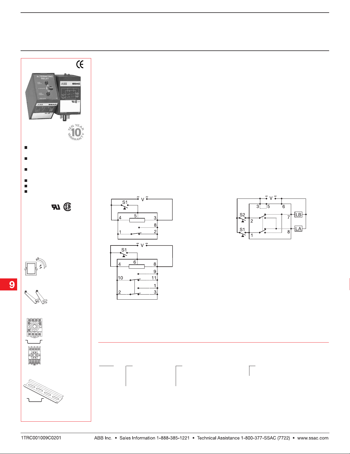
Relay contacts in above are isolated.
S1 = Primary Control Switch S2 = Lag Load Switch
OrOr
dering Tdering T
Or
dering T
OrOr
dering Tdering T
ARPARP
ARP
ARPARP
SeriesSeries
Series
SeriesSeries
ableable
able
ableable
X X
X
X X
InputInput
Input
InputInput
22
–
2 - 24 V AC –
22
4 4
–
4 - 120 V AC –
4 4
6 6
–
6 - 230 V AC –
6 6
1.
SPDT 8 Pin
DPDT 8 Pin Cross Wired
Duplexing (Cross Wired): Duplexing (Cross Wired):
Duplexing (Cross Wired): Duplexing models
Duplexing (Cross Wired): Duplexing (Cross Wired):
2.
DPDT 11 Pin
operate the same as alternating relays and when
both the Control (S1) and Lag Load (S2) Switches are
closed, Load A and Load B energize simultaneously.
The DPDT 8-pin, cross wired option, allows extra
system load capacity through simultaneous
operation of both motors when needed. Relay
contacts are not isolated.
Dashed lines are internal connections.
V = Voltage LA = Load A LB = Load B
XX
X
XX
Output FormOutput Form
Output Form
Output FormOutput Form
1 1
1 - SPDT, 8 Pin –
1 1
2 2
2 - DPDT, 11 Pin Blank - No Switch
2 2
3 3
3 - DPDT, 8 Pin Cross Wired
3 3
XX
X
XX
Switch OptionSwitch Option
Switch Option
Switch OptionSwitch Option
SS
S - Rotary Switch
SS
3.
See accessory pages for
specifications.
Example P/N:Example P/N:
Example P/N:
Example P/N:Example P/N:
ARP41S, ARP63ARP41S, ARP63
ARP41S, ARP63
ARP41S, ARP63ARP41S, ARP63
ARP02B01 07.01.04
Low Voltage Products & Systems9.26
Page 2
Alternating RelayAlternating Relay
Alternating Relay
Alternating RelayAlternating Relay
ARP Series
Motor Duplexor
Technical Data Technical Data
Technical Data
Technical Data Technical Data
InputInput
Input
InputInput
Voltage 24, 120, or 230 V AC
Tolerance 24 V AC -15% ... +20%
120 & 230 V AC -20% ... +10%
Line Frequency 50 ... 60 Hz
OutputOutput
Output
OutputOutput
Type Electromechanical relay
Form SPDT, or DPDT, or cross wired DPDT
Rating 10 A resistive at 120/240 V AC & 28 V DC; 1/3 hp at 120/240 V AC
Maximum Voltage 250 V AC
Life Mechanical -- 1 x 10
ProtectionProtection
Protection
ProtectionProtection
Isolation Voltage ≥ 1500 V RMS input to output
MechanicalMechanical
Mechanical
MechanicalMechanical
Mounting Plug-in socket
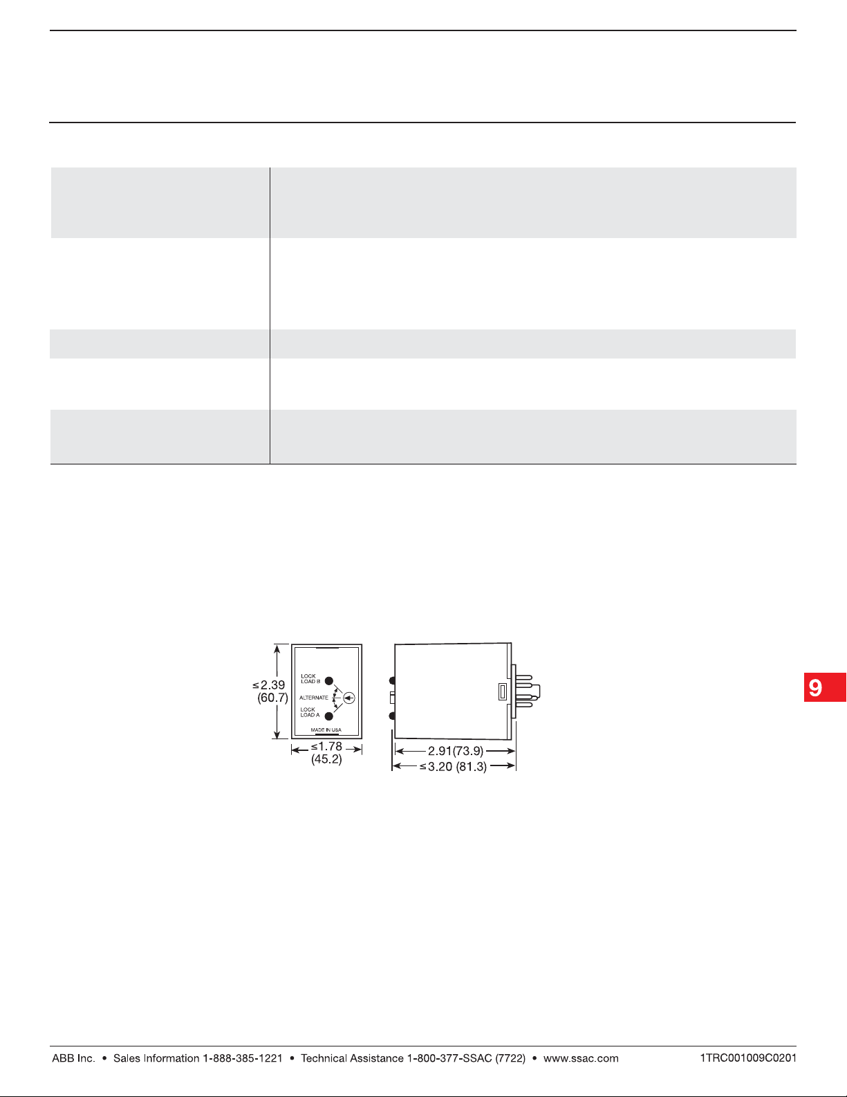
Package 3.2 x 2.39 x 1.78 in. (81.3 x 60.7 x 45.2 mm)
Termination 8 Pin octal or 11 Pin magnal
EnvironmentalEnvironmental
Environmental
EnvironmentalEnvironmental
Operating Temperature -20°C ... +60°C
Storage Temperature -30°C ... +85°C
Weight ≅ 5.6 oz (159 g)
Electrical -- 1 x 10
7
6
ARP02B01 07.01.04
Mechanical View Mechanical View
Mechanical View
Mechanical View Mechanical View
Inches (Millimeters)
Low Voltage Products & Systems 9.27
 Loading...