

Page 1
Alternating FlasherAlternating Flasher
Alternating Flasher
Alternating FlasherAlternating Flasher
AF Series
Solid State Flasher
Alternately Flashes Two High
Current Loads
High Surge Capacity -- Up
to 200 A
Small Size -- 2 x 2 x 1.30 in.
(50.8 x 50.8 x 33 mm)
Totally Solid State &
Encapsulated
DescriptionDescription
Description
DescriptionDescription
The AF Series offers a high inrush capacity of up to
200 A. These devices exceed mechanical type relays
in both performance and lifespan. The AF Series is
constructed with no moving parts to arc, wear, and
eventually fail; 100 million operations are typical.
Circuitry is encapsulated to provide protection against
vibration and moisture, making the AF Series ideal for
outdoor applications.
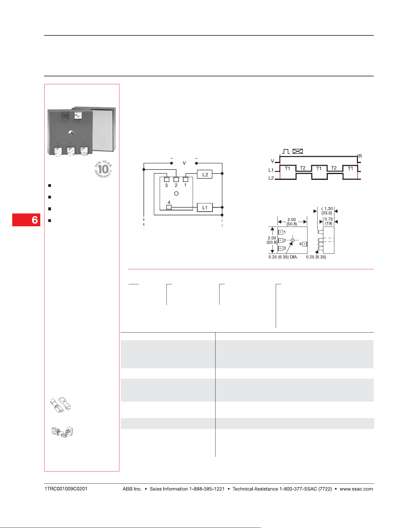
ConnectionConnection
Connection
ConnectionConnection
OperationOperation
Operation
OperationOperation
Upon application of input voltage T1 begins, Load 1 is
ON and Load 2 is OFF. At the end of T1, T2 begins
and Load 2 is now ON and Load 1 is OFF. At the end
of T2, T1 repeats and this sequence continues until
input voltage is removed. The duration of T1 and T2 is
approximately equal.
Reset: Reset:
Reset:
Removing input voltage resets the flasher.
Reset: Reset:
FunctionFunction
Function
FunctionFunction
Flasher (Alternating)
V = Voltage L1 = Load 1 L2 = Load 2
R = Reset T1 = ON Time T2 = OFF Time
T1 ≅ T2
Mechanical View Mechanical View
Mechanical View
Mechanical View Mechanical View
AccessoriesAccessories
Accessories
AccessoriesAccessories
Female quick connect
P/Ns:
P1015-13P1015-13
P1015-13
(AWG 10/12)
P1015-13P1015-13
P1015-64 P1015-64
P1015-64
(AWG 14/16)
P1015-64 P1015-64
P1015-14 P1015-14
P1015-14
(AWG 18/22)
P1015-14 P1015-14
Quick connect to
screw adaptor
P1015-18 P1015-18
P/N:
P1015-18
P1015-18 P1015-18
Inches (Millimeters)
OrOr
dering Tdering T
Or
dering T
OrOr
dering Tdering T
AF AF
AF
AF AF
SeriesSeries
Series
SeriesSeries
Example P/N: Example P/N:
Example P/N:
Example P/N: Example P/N:
TT
echnical Dataechnical Data
T
echnical Data
TT
echnical Dataechnical Data
Operation Alternating solid state flasher rated for continuous duty
Flash Rate Factory fixed at 10, 30, 60, 90, 120, or 140 flashes
Custom Flash Rate Specify as any number between 10 & 140, inclusive
Ratio ≅
InputInput
Input
InputInput
Input Voltage, Frequency 24, 120, or 230 V AC +/-15%, 50 ... 60 Hz
Output Output
Output
Output Output
Load Type Incandescent or resistive
Maximum Load Rating 6, 10, & 20 A steady state
Inrush 10 times steady state current
MechanicalMechanical
Mechanical
MechanicalMechanical
Mounting * Surface mount with one #10 (M5 x 0.8) screw
Package 2 x 2 x 1.30 in. (50.8 x 50.8 x 33 mm)
ProtectionProtection
Protection
ProtectionProtection
Circuitry Encapsulated
Environmental Environmental
Environmental
Environmental Environmental
Operating / Storage Temperature -20°C ... +60°C / -40°C ... +85°C
Humidity 95% relative, non-condensing
Weight ≅ 2.9 oz (82 g)
ableable
able
ableable
XX
X
XX
InputInput
Input
InputInput
11
–
1 - 24 V AC
11
22
–
2 - 120 V AC
22
33
–
3 - 230 V AC
33
AF224 AF224
AF224
AF224 AF224
XX
X
XX
Output RatingOutput Rating
Output Rating
Output RatingOutput Rating
11
–
1 - 6 A
11
2 2
–
2 - 10 A
2 2
33
–
3 - 20 A
33
Custom Flash Rate -
AF229-45 AF229-45
AF229-45
AF229-45 AF229-45
per min. +/-10%.
50%
XX
X
XX
Flash Rate (flashes per min.)Flash Rate (flashes per min.)
Flash Rate (flashes per min.)
Flash Rate (flashes per min.)Flash Rate (flashes per min.)
11
–
1 - 10
11
22
–
2 - 30
22
33
–
3 - 60
33
44
–
4 - 90
44
5 5
–
5 - 120
5 5
66
–
6 - 140
66
99
–
9 - _ _ _ Custom Flash Rate
99
See accessory pages for
specifications.
6.8
*Must be bolted to metal surface using the included heat sink compound.
The maximum mounting surface temperature is 90°C.
AF001B01 06.10.04
Low Voltage Products & Systems
 Loading...