

DST4W-PRO
Wireless DMX Transmitter
Receiver and Splitter
Instruction Manual
Model:
DST4W-PRO-3 3 pin DMX connectors
DST4W-PRO-5 5 pin DMX connectors
DST4W-PRO-C mixed DMX connectors
ATTENTION!
This instruction manual contains important information about
the installation and the use of equipment. Please read and
follow these instructions carefully. Always ensure that the
power to equipment is disconnected before opening the
equipment or commencing any maintenance work.
SRS Light Design s.r.o, Rybničná 36/D , 831 06 Bratislava, Slovak Republic tel:+421244681417,
fax:+421244681419, www.srslight.com , sales@srslight.com
IMPORTANT SAFETY INFORMATION
The following general safety precautions have to be observed during all phases of
operation, service, and repair of this equipment. Failure to comply with these precautions
or with specific warnings in this manual violates safety standards of design, manufacture,
and intended use of this equipment.
Do not operate in an explosive atmosphere
Do not operate this equipment in the presence of flammable gases or fumes. Operation of
any electrical instrument in such an environment constitutes a definite safety hazard.
Device should never be placed near or over a heat register or other source of heated air
or it should not be installed or operated without a proper ventilation.
Mains AC 85-265V connection
AC power is connected to the splitter via Neutrik PowerCon blue connector. Standard
supply is UNISCHUKO lead with Neutrik PowerCon. Always respect marking of L and N on
the connector for correct wiring of Line and Neutral.
Battery connection
Battery for DST4 power can be connected to screw terminal on the rear side of the
device. There is no strict requirement of polarity – you can use AC or DC power with the
limitation of voltage 12-24V.
DMX connection
DMX connectors are located on both sides of the splitter board. They are separated into
two groups. 1st group is wired in ratio 1:1 and marked as DMX input and DMX thru. This line
is not optically isolated and when the device is the last in line, it should be terminated by
the termination resistor of 120ohm wired between pins 2 and 3.
The 2nd part of the splitter consists of 4-way optically isolated lines marked with letters AD. Each line has a separate power supply, line driver and indication of signals D+, D- on
both signal lines. These LEDs are active when the splitter is retransmitting DMX signal
and there is no short circuit between data lines.
In case of a short circuit between data pins D+/D- and the CMN pin, the LED connected to
the data line will go off.
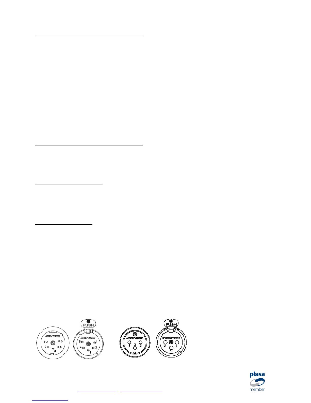
Pin 1 Common
Pin 2 Data -
Pin 3 Data +

SRS Light Design s.r.o, Rybničná 36/D , 831 06 Bratislava, Slovak Republic tel:+421244681417,
fax:+421244681419, www.srslight.com , sales@srslight.com
Front panel:
Rear panel:
Device in use / service:
By default, Power LED indicates the device is on main power. If the power light does not
light up, please check main power input. The unit can be supplied with AC85-264V or
AC/DC battery power. There is no polarity restriction for this port. You can use AC or DC
power with 12-24V.
When the DMX cable is connected to the device, the LEDs marked as D+ and D- go ON for
the side marked as DMX input, thru and this indicates that the DST4W-PRO is receiving
the DMX signal. Blinking frequency of these LEDs also indicates refresh rate of the DMX
signal. Fast blinking – high refresh rate, slow blinking – low refresh rate.
On the rear panel of the DST4W-PRO, you can see outputs A-D, which are retransmitting
the input to the optically isolated outputs. If any of the data LEDs is off, unplug the signal
cable corresponding to this output and check the cable for short circuit between D+ and
CMN or D- and CMD lines.

SRS Light Design s.r.o, Rybničná 36/D , 831 06 Bratislava, Slovak Republic tel:+421244681417,
fax:+421244681419, www.srslight.com , sales@srslight.com
DMX-only operation
For DMX operation, turn off the W-DMX module by
holding the MODE button. Both W-DMX and MODE
buttons should be RED.
Connect the DMX cable to DMX-IN connector and
use the DST4W-PRO as a standard DMX isolated
splitter one to four.
Once the DMX signal is active, the LEDs marked as
D+ and D- will go ON for both input module and
output modules A-D.
How to change W-DMX Receiver to Transmitter and vice versa:
Turn off the splitter by unplugging the power cable. Hold the W-DMX button and plug in
the power cable. The unit has now changed its state. Without holding the W-DMX button,
the unit will stay in the same mode as it was before.
W-DMX receiver: Bargraph shows signal or is off, if the unit is not linked to any
transmitter.
W-DMX transmitter: Bargraph’s green LEDs are lighting one by one showing that the unit
is transmitting DMX signal over the air.
W-DMX/DMX operation
For the W-DMX/DMX operation, turn the W-DMX module on by holding the MODE button.
Both W-DMX and MODE buttons should light GREEN.
Connect the DMX cable to DMX in/thru connector and use the DST4W-PRO as a standard
DMX isolated transmitter. For receiver mode, use outputs A—D.
Once the DMX signal is active, the LEDs marked as D+ and D- will go on for both input
module and output modules A-D.

SRS Light Design s.r.o, Rybničná 36/D , 831 06 Bratislava, Slovak Republic tel:+421244681417,
fax:+421244681419, www.srslight.com , sales@srslight.com
W-DMX Receiver/Splitter
You can use the DST4W-PRO as a Receiver with the Splitter output.
There is an automatic back-up of the W-DMX line using the cable connection. If the W-DMX
is linked to the transmitter and the signal quality is poor, the W-DMX active LED goes off
and the splitter will retransmit signal from cable in/thru port. In normal state, when the WDMX signal quality is good, the W-DMX active LED is on.
The W-DMX button has only one function – logging off from the linked transmitter.
W-DMX LED signalization in the Receiver mode:
Receiver Mode unlinked
MODE LED is GREEN and the receiver W-DMX LED is RED. The bargraph does not show
the signal strength.
Receiver Mode linked
MODE LED is GREEN and the receiver W-DMX LED is RED or GREEN according to the DMX
connection on the Transmitter’s side. The bargraph shows the signal strength.

SRS Light Design s.r.o, Rybničná 36/D , 831 06 Bratislava, Slovak Republic tel:+421244681417,
fax:+421244681419, www.srslight.com , sales@srslight.com
W-DMX Transmitter/splitter
You can use the DST4W-PRO in the Transmitter and DMX splitter mode at the same time.
The DMX signal from input/thru is sent out via Wireless DMX to all other linked W-DMX
devices.
Signal bargraph LEDs are blinking in a row to indicate that the module is in the
Transmitter mode.
W-DMX button has two functions:
Short press: Linking unlinked Receivers,
Long press: Unlinking all linked Receivers
W-DMX LED signalization in Transmitter mode:
Transmitter without DMX
MODE LED is GREEN and the W-DMX LED is RED or GREEN according to the status of the
DMX connected to the in/thru port.
To add an unlinked Receiver, press the W-DMX button for a second. The unlinked
Receiver will start to blink fast.
After a successful pairing, the W-DMX buttons on both units will blink slowly showing the
same status of the DMX connected to the Transmitter.
Transmitter with DMX
DMX is connected to the Transmitter and transmitting the W-DMX signal. W-DMX LEDs on
both Receiver and Transmitter are GREEN.
Bargraph is active and shows the W-DMX signal strength and the DMX status on the
Receiver.

SRS Light Design s.r.o, Rybničná 36/D , 831 06 Bratislava, Slovak Republic tel:+421244681417,
fax:+421244681419, www.srslight.com , sales@srslight.com
Technical data
Mains input:
AC 100-255V / 50-60Hz / 5W
Battery input:
AC12-24V / 5W or DC12-24V /5W
Input / Output:
4x USITT DMX512 /RS485/ isolated up to 1000V
Size/Weight:
Metal box with powder coating: 234x154x62mm, 1.7kg
Mounting points:
Located symmetrically on the base plate, 8mm-wide hole for securing line
Grid of mounting points: 222x78mm, 4 x rubber feet on the bottom
Operating temperature:
-10
ºC /
+45 ºC
Warranty:
Two-Year /24-month/ warranty
DECLARATION OF CONFORMITY
According to the guidelines 89/336 EEC and 92/31 EEC:
Name of producer: SRS Light Design s.r.o.
Address of producer: Rybnicna 36/D, SK- 83106 Bratislava, Slovak Republic
Declares that the product
Name of product: DST4W-PRO or DST4W-PRO LR, 4-way Wireless DMX / DMX splitter
Type: DST4W-PRO, DST4W-PRO LR
Corresponds to the following product specifications and R&TTE Directive of the European
Union:
Safety: EN60065, resp. EN 60950
EMC: EN55103-1, resp. EN55103-2
Radio: EN 301 489-1; 301 489-17; EN 300-328-1; EN 300-328-2
Bratislava, 10th of May, 2011
Robert Sloboda
 Loading...