

SRS Light Design DSR10N, DSR10N-3, DSR10N-5 Instruction Manual
SRS Light Design s.r.o, Rybničná 36/D , 831 06 Bratislava, Slovak Republic
tel:+421244681417, fax:+421244681419, www.srslight.com , sales@srslight.com
10-way DMX Splitter
Instruction Manual
Model:
DSR10N: RJ45 connectors
DSR10N-3 : 3pin/RJ45 DMX connectors
DSR10N-5 : 5pin/RJ45 DMX connectors
Version 2: 11/2015
ATTENTION!
This instruction manual contains important information about the
installation and the use of equipment. Please read and follow these
instructions carefully.
Always ensure that the power to equipment is disconnected before
opening the equipment or commencing any maintenance work.
SRS Light Design s.r.o, Rybničná 36/D , 831 06 Bratislava, Slovak Republic
tel:+421244681417, fax:+421244681419, www.srslight.com , sales@srslight.com
IMPORTANT SAFETY INFORMATION
The following general safety precautions have to be observed during all phases of
operation, service, and the repair of this equipment. Failure to comply with these
precautions or with specific warnings in this manual violates safety standards of
design, manufacture, and the intended use of this equipment.
Do not operate in an explosive atmosphere!
Do not operate this equipment in the presence of flammable gases or fumes.
Operation of any electrical instrument in such an environment constitutes a definite
safety hazard.
Water, moisture, heat and humidity
Do not operate this equipment near water or in areas with wet floors or in high
humidity atmosphere where condensation forms on the equipment. It should never
be placed near or over a heat register or other source of heated air and it should not
be installed or operated without proper ventilation.
DMX connections
DMX 3/5/RJ45 XLR connectors are located on the front panel of device. These are
separated into two groups. First group is wired in ratio 1:1 and marked as IN and OUT.
This line should be terminated by the termination switch marked as “T”. When line is
terminated by 120R resistor, the red LED T indicator is on.
The other part of splitter consists of 10-way optically isolated lines marked with
numbers 1 - 10. Each line has a separate power supply and a line driver + indication
of signal on both signal lines with two LEDs marked as 2, 3.
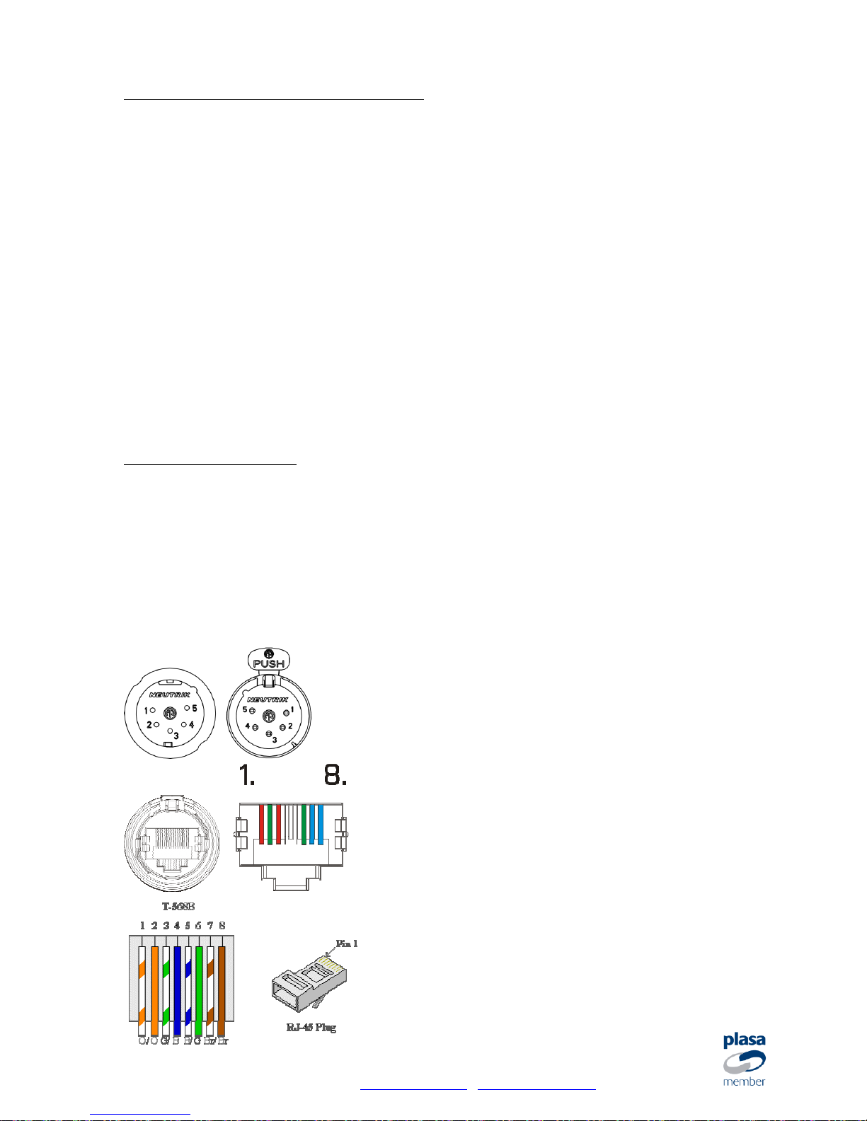
Pin 1 Ground / Common
Pin 2 Data Pin 3 Data +
Pin 4, 5 NC
Pin 1, 3 Data +
Pin 2, 6 Data Pin 4, 5 NC
Pin 7, 8 Ground / Common
 Loading...