

Page 1
( 1 / 16)
Instruction Manual
Models:
version 02.01 since 1 June 2017
ATTENTION!
This instruction manual contains important information about the installation and the use of
the equipment. Please read and follow these instructions carefully.
Always ensure that the power to the equipment is disconnected before opening the
equipment or commencing any maintenance work.
RMCXX_en_manual_M175
Rack Hoist Controller
RMC12, RMC8
Page 2

( 2 / 16)
Safety information
IMPORTANT INSTRUCTIONS
All safety and operating instructions should be read before the equipment is installed or operated.
IMPORTANT SAFETY INFORMATION
The following general safety precautions have to be observed during all phases of operation, service,
and the repair of this equipment. Failure to comply with these precautions or with specific warnings
in this manual violates safety standards of design, manufacture, and the intended use of this
equipment.
Do not operate in an explosive atmosphere!
Do not operate this equipment in the presence of flammable gases or fumes. Operation of any
electrical instrument in such an environment constitutes a definite safety hazard.
Water, moisture, heat and humidity
Do not operate this equipment near water or in areas with wet floors or in high humidity atmosphere
where condensation forms on the equipment. It should never be placed near or a over heat register
or other source of heated air and it should not be installed or operated without proper ventilation.
Page 3

( 3 / 16)
Functions and Control
RMC hoist controller was designed to control up to 12 (RMC-12) electrically compatible motors either
separately or simultaneously; via DIGITAL cable remote or locally on the RMCseries base unit.
All electrical components carry their own individual CE certification and comply with European
Directives. The components are housed in a robust steel 19" rack case with powder coating.
Operation
The Motors/Hoists connected to the MCseries controller can be activated either individually or
simultaneously using the GO button located either on the corresponding RMCseries controller base
or on the remote controller.
How to start
• Connect the Main plug to the 230V AC power supply /on MCseries controller this is marked
as an “AUX” output/
• Connect the Remote connector to the MCseries controller
• Connect Remote2/E-stop connector to the MCseries controller
• Select type of operation LOCAL / REMOTE using the KEY switch
• Check if the emergency STOP button is not engaged
• Engage the gear lever corresponding to each motor to the required position:
o UP - Lever in upper position
o STAY – Lever in middle position
o DOWN - Lever in lower position
• Pushing the GO button will activate the motors that will move simultaneously
• Releasing the GO button will simultaneously cease the movement of the motors
• When the device is not being used, it is highly recommended to turn it off using the key
switch or the STOP button
To Move a Single Motor:
• Set the UP/DOWN toggle switch for the motor to be moved to the desired direction. The
associated LED will light green for UP and red for DOWN.
• Hold the GO button until the motor has moved to the desired height and release.
To Move Several Motors:
• Set the UP/DOWN toggle switches for each motor to be moved to the desired direction.
Every associated LED will light green for UP and red for DOWN.
• Hold the GO button until the motors have moved to the desired height and release.
Page 4
( 4 / 16)
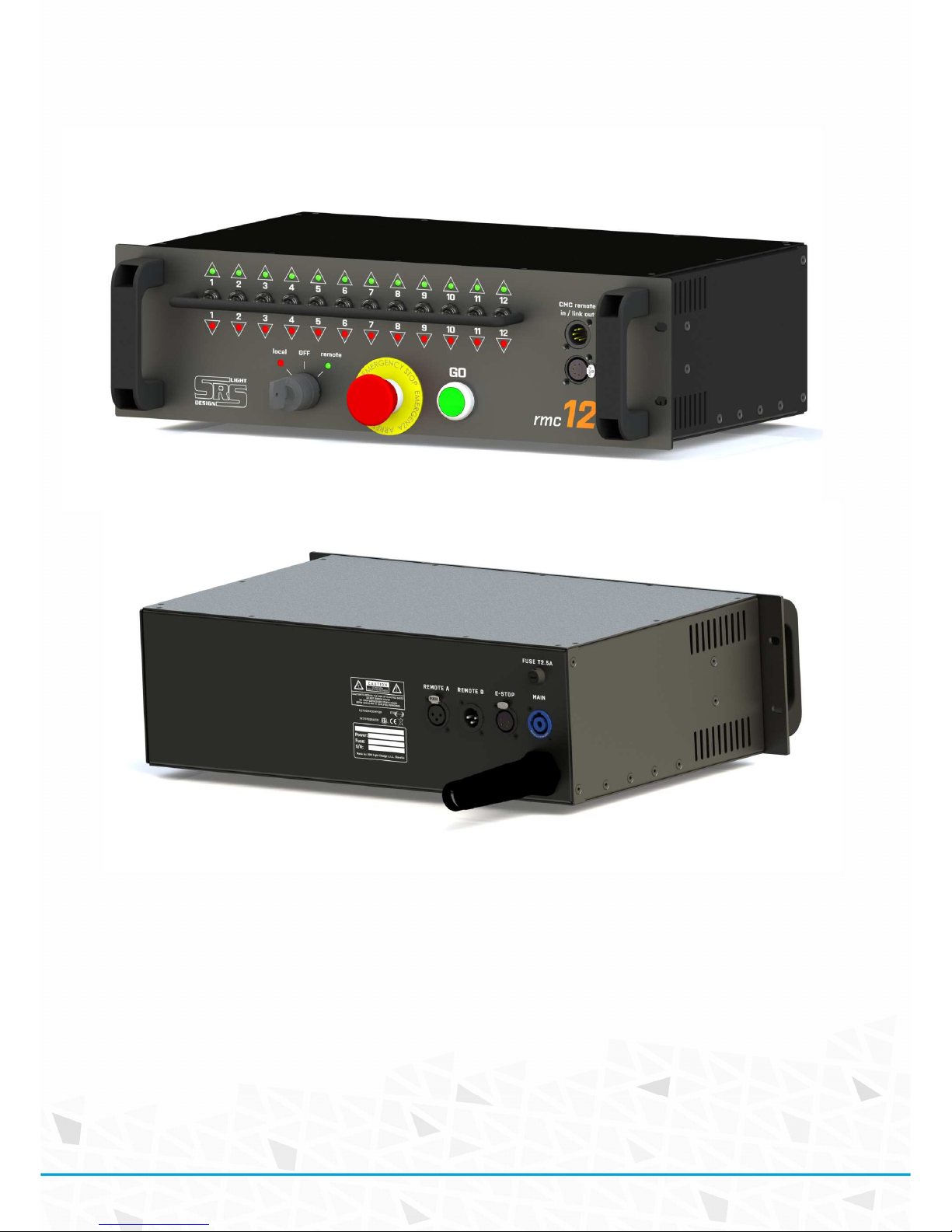
RMCseries base unit
RMCseries front panel
RMCseries rear panel
• E-stop connector NC4FDL
• Remote A / Remote B link connectors are 3-pin /NC3MDL+NC3FDL/ or NC3MAH and NC3FAH
• When controllers are linked via LINK, the STOP and GO signals of all controllers in LOCAL
mode work simultaneously.
Page 5
( 5 / 16)
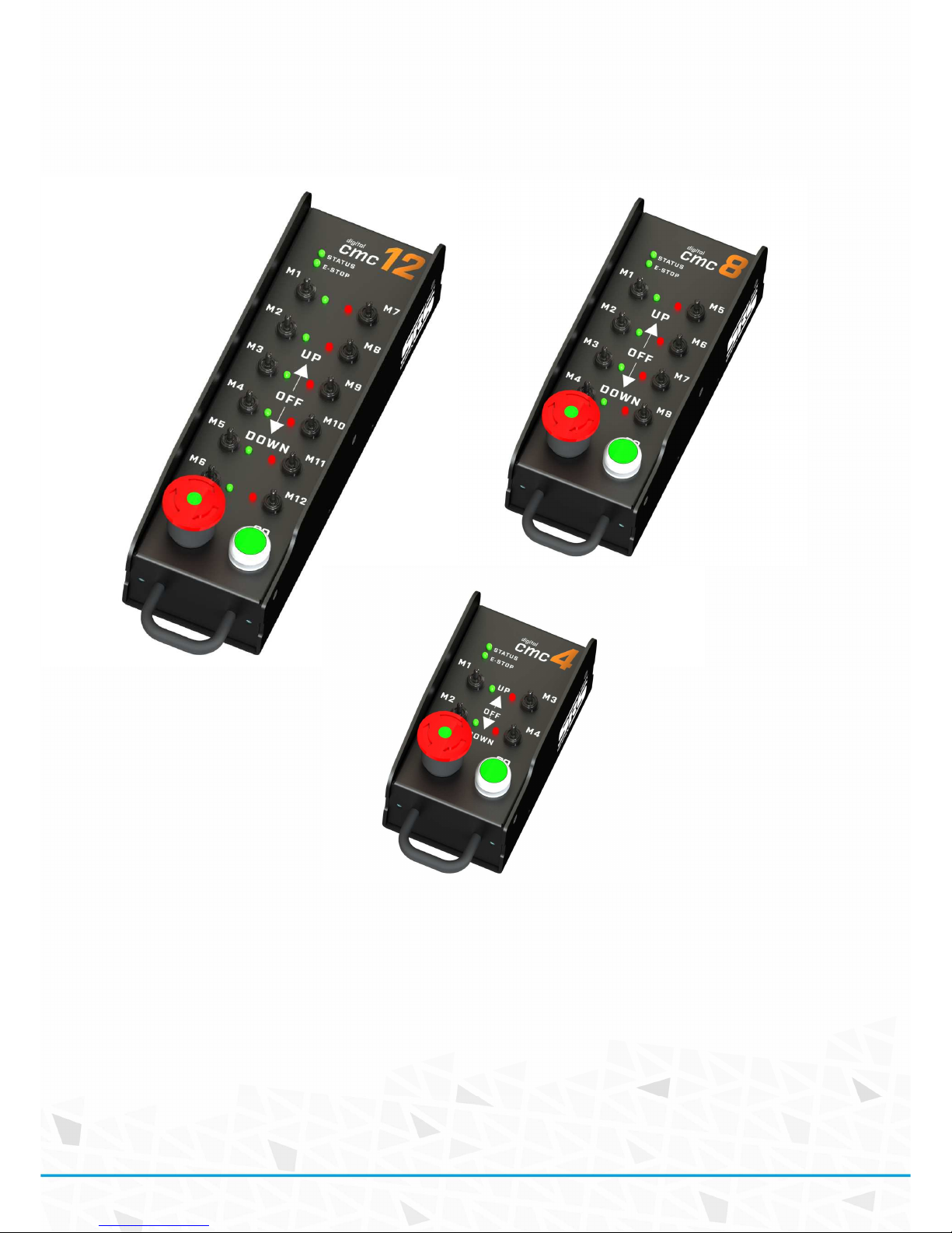
Optional CMC-DIGITAL remote
CMC-DIGITAL allows controlling of the RMCseries via the DIGITAL wired remote
STOP:
This latching pushbutton switch turns the Hoist Control system off. Once the STOP button has been
pressed, it is locked into the off position and must be rotated clockwise to be released.
GO:
This pushbutton switch turns the selected channels of Hoist Control system on when they are
active. Once the GO button has been pressed, the energizing of the hoists is on.
DIRECTION SWITCHES:
They allow changing the direction of movement for each motor/hoist separately.
Page 6

( 6 / 16)
DIRECTION SWITCH LED
• Green UP
• Red DOWN
• No light stays in position
STATUS LED:
• Green Device ready for action
• Red Indicates that GO button is active
• Orange Indicates the activity of direction switch; LED blinks with the movement
E-STOP STATUS LED:
• Green E-STOP system is OK
• Orange Indicates that the system needs to be reset
• Red E-STOP is active somewhere in the system
• RED blinking E-STOP button is pressed on the device
CMC-DIGITAL Remote connector
Neutrik NC5-FDL
Pin Function note
1 Data CMN Data Common
2 Data - Data Minus
3 Data+ Data Plus
4 DC1
Power supply for
CMC
DC12-36V
5 DC2
Power supply for
CMC
DC12-36V
Housing + Dimensions
2.0mm+3.0mm lightweight aluminum box
CMC-12D: 107 x 330 x 105 mm
CMC-8D: 107 x 260 x 105 mm
CMC-4D: 107 x 190 x 105 mm
1.5mm lightweight box
CMC-24D: 107 x 330 x 105 mm
Page 7

( 7 / 16)
Output wiring
Remote multipin connector
Amphenol DS3106A28-21P
Pin Function CMC12A CMC8A
1 M1 down X X
2 M1 up V V
3 M2 down c c
4 M2 up d d
5 M3 down
b b
6 M3 up h h
7 M4 down j j
8 M4 up k k
9 M5 down e e
10 M5 up Z Z
11 M6 down W W
12 M6 up L L
13 M7 down K K
14 M7 up U U
15 M8 down m m
16 M8 up f f
17 M9 down
R -
18 M9 up P 19 M10 down N -
20 M10 up M -
21 M11 down F 22 M11 up E 23 M12 down T 24 M12 up S -
25 Contactor ON
a a
26 AC1 24V g g
27 AC1 24V n n
28 AC1 24V p p
29 AC2 24V
r r
30 GROUND s s
E-stop connector
Unit is equipped with certified SIL3 E-STOP safety relay. For additional safety, up to two sources of
E-STOP can be connected. Usually one of them is the RMC unit and the other one should be the load
cell unit. According to the requirement, both lines are normally closed – NC. Because of this, it is
necessary to fit the safety breach /MXX connector with a short circuit between pins 1 and 2, and
pins 3 and 4. Both lines are separated and CANNOT be connected together – otherwise it will not be
possible to reset the safety circuit.
Neutrik NC4FXX Pin 1: Safety line 1 IN
Pin 2: Safety line 1 OUT
Pin 3: Safety line 2 IN
Pin 4: Safety line 2 OUT
Page 8

( 8 / 16)
Remote1/Remote2 connector or LINK connectors
LINK connectors are used for linking of two or more RMC units together in case that linked operation
of units is required. For link unit need be in the local mode. E-STOP and GO signal is sent via network
to all linked controllers.
RS485 is used as a communication link.
Neutrik NC3FXX/MXX Pin 1: Data common
Pin 2: Data minus
Pin 3: Data plus
CMC-DIGITAL connection
CMC remote connectors are used for linking of RMC with the CMC-xx DIGITAL remote for remote
operation with option to change directions. Each RMC needs to be connected with CMC-xx DIGITAL
via 5pole digital cables.
STOP and GO signal is sent only to controller – not to other linked units.
RS485 is used as a communication link.
Neutrik NC5FXX/MXX Pin 1: Data common
Pin 2: Data minus
Pin 3: Data plus
Pin 4: DC1
Pin 5: DC2
Page 9

( 9 / 16)
Linking of RMCseries units
Up to 10 RMC base units can be linked together for a group operation of GO buttons.
For linking of RMC base, use a 3-pin XLR cable connected as 1:1 between pins 1-3.
Data are transferred thru the RS485 line.
All connected devices will have GO/E-STOP button linked in the LOCAL mode.
Page 10

( 10 / 16)
Technical data
• Main Power: AC208-230V, 50/60Hz, T2.5
• *Optional : AC110V / 60Hz
Protections and Safety:
• Dry contacts – all outputs are galvanic isolated
• Double - Recessed Emergency stop + SIL3 safety module
• Double encoded data communication
• Load cell E-STOP
• External E-STOP option
• Software update via USB
Dimensions /W x D x H/:
RMC12: 483 x 365 x 132 mm
RMC8: 483 x 365 x 132 mm
Page 11

( 11 / 16)
Warranty
RMCseries hoist controller is covered by a 2-year manufacturer’s warranty. For extended warranty
conditions please contact the manufacturer at sales@srs-group.com.
Warranty covers the original factory installed components of the controller and their correct
functioning.
Warranty voids if any part or replacement components are installed or modified without authorization
from the manufacturer and/or the internal circuit is tampered or modified and/or the controller is
operated outside normal use conditions – electrical power supply is not conform or there is
connection error or mechanical damage of controller, including overload, improper use. The
manufacturer always helps you with repairing of your unit.
Page 12

( 12 / 16)
Declaration of conformity
DECLARATION OF CONFORMITY
According to guidelines 89/336 EEC and 92/31 EEC, 90/337 CEE Annex II A:
Name of producer:
SRS Group s.r.o.
Address of producer:
Rybnicna 36/D, SK- 83106 Bratislava, Slovak Republic
www.srs-group.com/ sales@srs-group.com, +421244681417
Declares that the product
Name of product: RMCseries
hoist controller: RMC8, RMC12 and variants
Types
:
RMC-8: Rack controller 8 channels
RMC-12: Rack controller 12 channels
Corresponds with following harmonized standards:
Safety:
EN60065, resp. EN 60950
EMC:
EN55103-1, resp. EN55103-2
And
Is in compliance with the following requirements:
Machinery directive
: 2006/42/EC
Low Voltage directive:
2006/95/EC
Bratislava, 31 October 2014
Robert Sloboda
Page 13

( 13 / 16)
Page 14

( 14 / 16)
Page 15

( 15 / 16)
Page 16

( 16 / 16)
Copyright 2017 SRS Group, s.r.o. | Specifications subject to change without notice.
Document: RMCXX_en_manual_M175 | Version 02.01 | Actual as of: 1 June 2017
SRS Group s.r.o.
Rybnicna 36/D | 831 07 Bratislava | Slovakia
Phone: +421 2 44 681 417 | Fax: +421 2 4468 1419
Email: sales@srs-group.com | www.srs-group.com
 Loading...