

Page 1

Version 4.2 (May 14, 2019)
User Manual
PTC10
Programmable Temperature Controller
Page 2

PTC10 Programmable Temperature Controller
Certification
Stanford Research Systems certifies that this product met its published specifications at the time of shipment.
Warranty
This Stanford Research Systems product is warranted against defects in materials and workmanship for a period of
one (1) year from the date of shipment.
Service
For warranty service or repair, this product must be returned to a Stanford Research Systems authorized service
facility. Contact Stanford Research Systems or an authorized representative before returning this product for repair.
Information in this document is subject to change without notice.
Copyright © Stanford Research Systems, Inc., 2018. All rights reserved.
Stanford Research Systems, Inc.
1290-C Reamwood Avenue
Sunnyvale, California 94089
Phone: (408) 744-9040
Fax: (408) 744-9049
www.thinkSRS.com
Printed in the USA
Page 3

Contents i
PTC10 Programmable Temperature Controller
Contents
Safety and preparation for use....................................................................................... v
Specifications .................................................................................................................. vii
Introduction 1
I/O cards ............................................................................................................................ 2
PTC320 thermistor/diode/RTD card .................................................................................... 2
PTC321 RTD reader ................................................................................................................ 5
PTC323 2-channel thermistor/diode/RTD card ................................................................... 6
PTC330 thermocouple reader .............................................................................................. 11
PTC420 AC output card........................................................................................................ 13
PTC430 50 W DC output card ............................................................................................. 14
PTC431 100W DC output card ............................................................................................ 15
PTC440 TEC driver ............................................................................................................... 17
PTC510 analog I/O card ....................................................................................................... 20
PTC520 digital I/O card ........................................................................................................ 20
Operation 23
Quick start tutorial ........................................................................................................ 24
Turn the instrument on .......................................................................................................... 24
The Select screen ................................................................................................................... 24
Configure the sensor inputs ................................................................................................... 24
If the sensor reading does not appear ................................................................................... 25
Plot data .................................................................................................................................. 25
Test the outputs ..................................................................................................................... 26
Set the data logging rate ......................................................................................................... 27
Save data to and retrieve data from a USB memory device ................................................ 27
Interface with a computer ...................................................................................................... 28
Control a temperature........................................................................................................... 29
Acquiring and logging data ........................................................................................... 36
Input filters .............................................................................................................................. 36
Custom calibration tables ...................................................................................................... 36
Virtual channels ...................................................................................................................... 38
Logging data to internal memory ........................................................................................... 39
Logging data to USB ............................................................................................................... 39
ADC sampling and logged data ............................................................................................. 39
Format of PTC10 log files ...................................................................................................... 40
Using the system fan ..................................................................................................... 41
Using PID feedback ........................................................................................................ 42
...................................................................... 42
Basic PID feedback concepts ................................................................................................. 42
Manual tuning .......................................................................................................................... 43
Automatic tuning algorithms .................................................................................................. 46
Using the automatic tuner...................................................................................................... 49
Front-panel controls ................................................................................................ ...... 52
Page 4

Contents ii
PTC10 Programmable Temperature Controller
USB logging indicator ............................................................................................................. 52
.............................................................................................................................. 52
.............................................................................................................. 52
....................................................................................................................... 53
.................................................................................................................. 54
........................................................................................................................... 54
................................................................................................................... 59
................................................................................................................... 64
..................................................................................................................... 78
Firm ware updates .......................................................................................................... 85
Replacing the clock battery .......................................................................................... 86
Remote programm ing 87
Connecting to the PTC10 ...................................................................................................... 87
Communication, assembly, and run-time errors .................................................................. 90
Concurrent macros ................................................................................................................ 90
Macro names .......................................................................................................................... 91
Command syntax ................................................................................................................... 91
Rem ote instructions ...................................................................................................... 95
General instructions ............................................................................................................... 95
IEEE 488.2 Instructions ........................................................................................................... 99
Program submenu ................................................................................................................ 103
System submenu ................................................................................................................... 106
<channel> submenu ............................................................................................................ 110
Error codes ........................................................................................................................... 121
Startup macro ....................................................................................................................... 122
Sam ple m acros ............................................................................................................. 123
Temperature profiles ........................................................................................................... 123
Control a feedback setpoint with an analog input .............................................................. 124
PID input scheduling ............................................................................................................. 124
Show channels with tripped alarms on the Numeric screen ............................................. 125
Make a virtual channel show the PID setpoint ................................................................ .... 125
Linearizing outputs when interfacing with external power supplies .................................. 125
Control instrument functions with the digital IO lines ....................................................... 126
Drive a solid state relay with the digital IO lines ................................................................. 127
PC applications 129
PTCFileConverter ....................................................................................................... 130
FileGrapher ................................................................................................................... 132
File menu ................................ ............................................................................................... 132
Edit menu .............................................................................................................................. 132
Process menu ....................................................................................................................... 134
Special menu ......................................................................................................................... 136
Command line and macro instructions ............................................................................... 137
Circuit description 141
Core system cards ....................................................................................................... 142
PTC212 CPU board ............................................................................................................. 142
PTC221 backplane ............................................................................................................... 142
Page 5

Contents iii
PTC10 Programmable Temperature Controller
PTC231 front panel .............................................................................................................. 144
PTC240 GPIB card ............................................................................................................... 145
I/O cards ........................................................................................................................ 146
PTC320 1-channel thermistor/diode/RTD reader ........................................................... 146
PTC321 4-channel RTD reader ........................................................................................... 147
PTC330 thermocouple reader ............................................................................................ 148
PTC420 AC output card...................................................................................................... 149
PTC430 50W DC output card ............................................................................................ 149
PTC431 100W DC output card .......................................................................................... 150
PTC440 TEC driver ............................................................................................................. 151
PTC510 analog I/O card ..................................................................................................... 152
PTC520 digital I/O card ...................................................................................................... 153
Parts List 155
PTC212 CPU board ............................................................................................................. 155
PTC221 backplane ............................................................................................................... 165
PTC231 front panel .............................................................................................................. 167
PTC240 GPIB option ........................................................................................................... 169
PTC320 1-channel thermistor, diode, and RTD reader .................................................... 170
PTC321 4-channel RTD reader ........................................................................................... 173
PTC330 thermocouple reader ............................................................................................ 176
PTC420 AC output card...................................................................................................... 180
PTC430 50W DC output card ............................................................................................ 182
PTC440 TEC driver ............................................................................................................. 184
PTC510 analog I/O card ..................................................................................................... 187
PTC520 digital I/O card ...................................................................................................... 189
Schematics 193
Page 6

Page 7

Safety and Preparation for Use v
PTC10 Programmable Temperature Controller
Line voltage
The PTC10 operates from an 88 to 264 VAC power source having a line frequency between 47
and 63 Hz.
Power entry module
A power entry module, labeled AC POWER on the back panel of the PTC10, provides
connection to the power source and to a protective ground.
Power cord
The PTC10 package includes a detachable, three-wire power cord for connection to the power
source and protective ground.
The exposed metal parts of the box are connected to the power ground to protect against
electrical shock. Always use an outlet which has a properly connected protective ground. Consult
with an electrician if necessary.
Grounding
A chassis grounding lug is available on the back panel of the PTC10. Connect a heavy duty
ground wire, #12AWG or larger, from the chassis ground lug directly to a facility earth ground to
provide additional protection against electrical shock.
Line fuse
Use a 10 A/250 V 3AB Slo-Blo fuse.
Operate only with covers in place
To avoid personal injury, do not remove the product covers or panels. Do not operate the
product without all covers and panels in place.
Serviceable parts
The PTC10 does not include any user serviceable parts inside. Refer service to a qualified
technician.
Page 8

Page 9
Specifications vii
PTC10 Programmable Temperature Controller
PTC10 temperature controller
Maximum PID rate 50 or 60 Hz, depending on AC line frequency
Data logging rate 10 samples/second/channel 1 sample/hour/channel (can be set
independently for each channel or globally for all channels)
Display resolution 0.001 °C, °F, K, V, A, W, etc. if 1000 < displayed value < 1000;
6 significant figures otherwise
PID feedback auto-tuning Single step response or relay tuning with conservative, moderate, and
aggressive response targets
Display 320 × 240 pixel touchscreen; numeric and graphical data displays.
Alarms Upper and lower temperaturelimits or rate-of-change limits can be set on each
channel. If exceeded, an audio alarm and a relay closure occur.
Computer interface USB, Ethernet, and RS-232; optional GPIB (IEEE488.2)
Power 10 A, 88 to 132 VAC or 176 to 264 VAC, 47 to 63 Hz or DC
Dimensions 17"× 5" × 18" (WHL)
Weight 25 lbs.
Warranty One year parts and labor on defects in material and workmanship.
PTC320 thermistor, diode, and RTD reader
Inputs One input for 2-wire or 4-wire thermistor, diode, or RTD
Connector 6-pin 240° push-pull DIN socket
Thermistors
Range 0 30, 100, 300 ; 1, 3, 10, 30, 100, 300 k ; 2.5 M
Excitation current
30 range 200 µA
100 range 100 µA
300 range 50 µA
1 k range 30 µA
3 k range 20 µA
10 k range 10 µA
30 k range 5 µA
100 k range 3 µA
300 k range 2 µA
2.5 M range 1 µA
Initial accuracy
30 range ±0.025
100 range ±0.06
300 range ±0.1
1 k range ±0.2
3 k range ±0.6
10 k range ±1.3
30 k range ±4
100 k range ±10
300 k range ±250
2.5 M range ±30 k
Drift due to temperature
30 range ±0.002 /°C
100 range ±0.006 /°C
300 range ±0.006 /°C
1 k range ±0.01 /°C
Page 10

Specifications viii
PTC10 Programmable Temperature Controller
3 k range ±0.03 /°C
10 k range ±0.1 /°C
30 k range ±0.15 /°C
100 k range ±0.5 /°C
300 k range ±3 /°C
2.5 M range ±2000 /°C
RMS noise
30 range 0.003
100 range 0.006
300 range 0.012
1 k range 0.02 (= 2 mK for 300 thermistor at 25°C)
3 k range 0.03 (= 0.8 mK for 1 k thermistor at 25°C)
10 k range 0.06 (= 0.6 mK for 2252 thermistor at 25°C)
30 k range 0.1 (= 0.3 mK for 10 k thermistor at 25°C)
100 k range 0.3 (= 0.2 mK for 30 k thermistor at 25°C)
300 k range 3 (= 0.7 mK for 100 k thermistor at 25°C)
2.5 M range 25 (= 1.8 mK for 300 k thermistor at 25°C)
Diodes
Excitation current output 10 µA
Initial accuracy ± 100 ppm
Drift ±5 ppm/°C
Voltage input 0 2.5 V
Initial accuracy 10 µV + 0.01% of reading
Drift ±5 ppm/°C
RMS noise 1.5 µV
RTDs
Range 0 30, 100, 300 ; 1, 3, 10, 30, 100, 250 k , 2.5 M
Excitation
30 range 3 mA
100 range 2 mA
300 range 1 mA
1 k range 500 µA
3 k range 200 µA
10 k range 100 µA
30 k range 50 µA
100 k range 10 µA
300 k range 5 µA
2.5 M range 1 µA
Initial accuracy
30 range ±0.004
100 range ±0.008
300 range ±0.02 (=±50 mK for Pt100 RTD at 25°C)
1 k range ±0.04
3 k range ±0.1
10 k range ±0.2
30 k range ±1
100 k range ±2.5
300 k range ±16
2.5 M range ±30 k
Drift due to temperature
30 range ±0.0006 /°C
100 range ±0.001 /°C
300 range ±0.0015 /°C (=±5 mK/°C for Pt100 RTD at 25°C)
1 k range ±0.005 /°C
3 k range ±0.01 /°C
10 k range ±0.03 /°C
Page 11
Specifications ix
PTC10 Programmable Temperature Controller
30 k range ±0.06 /°C
100 k range ±0.2 /°C
300 k range ±3 /°C
2.5 M range ±2000 /°C
RMS noise
30 range 0.00012
100 range 0.0003
300 range 0.0006 ( = 1.4 mK for Pt100 RTD at 25°C)
1 k range 0.0013
3 k range 0.003
10 k range 0.006
30 k range 0.012
100 k range 0.07
300 k range 0.25
2.5 M range 25
PTC321 Pt RTD reader
Inputs Four 4-wire inputs for 100 Pt RTDs
Connector 5-pin, 3.5mm header
Range 0 400
IEC751 Pt100 RTDs 215 °C to 850 °C
Excitation current 1 mA
Initial accuracy ±30 mK
Drift due to temperature 1.4 mK/°C
Drift due to time ±15 mK/year (at 25°C ambient temperature)
Noise 2 mK RMS (at 25°C sensor temperature and 10 samples/s)
Signal detection Card detects open and short circuit conditions
PTC323 thermistor, diode, and RTD reader
Inputs Two inputs for 4-wire thermistor, diode, or RTD
Connectors One 9-pin D-sub socket
RTDs and thermistors
Range 0 10, 30, 100, 300 ; 1, 3, 10, 30, 100, 300 k ; 2.5 M , or auto
Excitation current Low power High power
10 range 1 mA 3 mA
30 range 300 µA 3 mA
100 range 100 µA 2 mA
300 range 30 µA 1 mA
1 k range 10 µA 500 µA
3 k range 3 µA 200 µA
10 k range 1 µA 50 µA
30 k range 300 nA 50 µA
100 k range 100 nA 5 µA
300 k range 30 nA 5 µA
2.5 M range 1 µA 1 µA
Initial accuracy (AC current, at midrange)
10 range ±0.007 ±0.005
30 range ±0.03 ±0.005
100 range ±0.07 ±0.008
300 range ±0.25 ±0.015 (=±40 mK for Pt100 RTD at 25°C)
1 k range ±0.6 ±0.05
3 k range ±2 ±0.1
Page 12

Specifications x
PTC10 Programmable Temperature Controller
10 k range ±6 ±0.25
30 k range ±25 ±1
100 k range ±150 ±4
300 k range ±1 k ±13
2.5 M range ±3 k ±3 k
Typical drift due to temperature (at midrange)
10 range ±0.0002 /°C ±0.0001 /°C
30 range ±0.0004 /°C ±0.0001 /°C
100 range ±0.002 /°C ±0.0002 /°C
300 range ±0.004 /°C ±0.0004 /°C
1 k range ±0.01 /°C ±0.001 /°C
3 k range ±0.06 /°C ±0.003 /°C
10 k range ±0.2 /°C ±0.01 /°C
30 k range ±1 /°C ±0.02 /°C
100 k range ±3 /°C ±1 /°C
300 k range ±20 /°C ±2 /°C
2.5 M range ±30 /°C ±50 /°C
RMS noise (DC current, at midrange)
10 range 0.0003 0.0001
30 range 0.001 0.0001
100 range 0.002 0.0002
300 range 0.006 0.0003 ( = 0.8 mK for Pt100 RTD at 25°C)
1 k range 0.02 0.0007
3 k range 0.06 0.002
10 k range 0.2 0.007
30 k range 1.0 0.008
100 k range 6 0.12
300 k range 40 0.2
2.5 M range 10 10
Diodes
Excitation current output 10 µA
Initial accuracy ± 100 ppm
Drift ±5 ppm/°C
Voltage input 0 2.5 V
Initial accuracy 10 µV + 0.01% of reading
Drift ±5 ppm/°C
RMS noise 3 µV
PTC330 thermocouple reader
Inputs Four optoisolated thermocouple inputs
Connector Mini thermocouple jacks
Thermocouple types E, J, K, N, or T
Range ±500 mV
Type E 270 °C to 980 °C (range of calibration table with cold junction at 25°C)
Type J 210 °C to 1177 °C
Type K 270 °C to 1342 °C
Type N 270 °C to 1281 °C
Type T 270 °C to 383 °C
Input capacitance <1 pF
Accuracy ±500 mK (over 12 months)
Noise 20 mK RMS (at 10 samples/s)
Drift due to temperature 20 mK/°C (type K thermocouple at 164.0 K)
CMRR 100 dB
Common mode isolation 250 VAC
Page 13

Specifications xi
PTC10 Programmable Temperature Controller
PTC420 AC output card
Output One line voltage output switched by solid-state relay
Connector NEMA 5-15 (3-prong North American wall socket); a heater cable with a
mating plug on one side and stripped ends on the other is included
Output voltage 120/240 VAC
Max. output current 5 A
On/off cycle time Adjustable between 1 and 240 s
Max. line voltage 250 VAC
Surge current 100 A max. (non-repetitive)
Output resolution 0.1% at 10 s cycle time
Heater resistance (min.) 24 (110 VAC), 46 (230 VAC)
PTC430 50 W DC output card
Output One linear, unipolar DC current source
Connector Two banana jacks, 0.75 inch center-to-center spacing
Range 50 V 1A, 20 V 2 A, 50 V 0.5A, 20 V 0.5 A,50 V 0.1A, or 20 V 0.1 A
Output resolution 24 bits with dithering enabled or 16 bits with dithering disabled
Accuracy ±1 mA (1 A range)
±0.1 mA (0.5 A range)
±0.01 mA (0.1 A range)
Noise (rms), 50 load, 6 µA (50 V 1 A and 20 V 2 A ranges)
DC 10 Hz 1.5 µA (0.5 A range)
0.2 µA (0.1 A range)
PTC431 100W DC output card
Output One unipolar DC current source
Connector #6 screw terminals. Accepts 12 22 AWG wire or #6 spade terminals up to
-lb.
Range 50 V 2A, 50V 0.6A, 50V 0.2A, 20V 2A, 20V 0.6A, 20V 0.2A
Output resolution 16 bits
Accuracy ±1 mA (2 A range)
±0.5 mA (0.6 A range)
±0.2 mA (0.2 A range)
Noise (rms), 25 load, 5 µA (2 A range)
DC 10 Hz 1.5 µA (0.6 A range)
0.5 µA (0.2 A range)
PTC440 TEC driver
Output One linear, bipolar DC current source
Input One 2- or 4-wire thermistor/RTD/IC temperature sensor input
Connector One 15-pin DB15-F
TEC driver
Output current -5 A +5A
Maximum power 50W
Compliance voltage 12 V (at 0 A current)
Output resolution 0.15 mA
Accuracy ±5 mA
Current noise 0.02 mA (at 0.5A current, 22 ohm resistive load, 0.01-10 Hz bandwidth)
Page 14

Specifications xii
PTC10 Programmable Temperature Controller
Temperature sensor input
Compatible sensors
Thermistors 2 or 4-wire NTC thermistors
RTDs 4-wire platinum RTDs, 100 1000 at 0°C
IC sensors LM335, AD590, or equivalent
Excitation current 10 µA, 100 µA, or 1 mA
Input range
Resistance 1 250 k
Voltage 0 2.5V
Current 0 1 mA
RMS electronic noise (sensor at 25°C)
10 µA excitation
1 k thermistor 0.7 = 15 mK
2252 thermistor 0.6 = 5 mK
10 k thermistor 1 = 4 mK
100 µA excitation
1 k thermistor 0.1 = 1.5 mK
2252 k thermistor 0.1 = 0.7 mK
10 k thermistor 0.2 = 0.5 mK
1 mA excitation
100 Pt RTD 0.003 = 8 mK
LM135/235/335 4 mK RMS
AD590/592 6 mK RMS
Initial accuracy
10 µA excitation
1 k thermistor 1.2 = 30 mK
2252 thermistor 10 = 100 mK
10 k thermistor 66 = 150 mK
100 µA excitation
1 k thermistor 0.06 = 1.6 mK
2252 k thermistor 0.1 = 10 mK
10 k thermistor 0.5 = 1.1 mK
1 mA excitation
100 Pt RTD 0.004 = 5 mK
LM135/235/335 70 mK
AD590/592 400 mK (sensor at 25°C)
Thermal drift
10 µA excitation
100 µA excitation
1 mA excitation
LM135/235/335
AD592/592
Analog I/O
Inputs/outputs 4 voltage I/O channels, independantly configurable as inputs or outputs
Connector 4 BNC jacks
Range ±10 V
Resolution 24-bit input, 16-bit output
ADC noise 30 µV RMS = 100 µV p-p (10 samples/s)
Digital I/O
Digital I/O
Inputs/outputs 8 optoisolated TTL lines, configurable as either 8 inputs or 8 outputs
Page 15

Specifications xiii
PTC10 Programmable Temperature Controller
Connector One DB-25F
Relays
Outputs 4 independent SPDT relays
Connector One 12-pin 3.5mm header
Maximum current 5 A
Maximum voltage 250 VAC
Page 16

Page 17

Introduction 1
PTC10 Programmable Temperature Controller
Introduction
The PTC10 is a high-performance, general-purpose laboratory temperature controller that can
monitor and control temperatures with millikelvin resolution. Its features include:
Modular design
The PTC10 can accept up to four I/O cards, each of which can read up to four temperature
sensors and/or drive one heater. The instrument can be customized by selecting the I/O cards best
suited to your application. The PTC10 also comes standard with four ±10V I/O channels that can
be used with external amplifiers to read signals and drive heaters.
Reads up to 16 tem perature sensors
Temperature input cards are available for reading thermocouples, RTDs, thermistors, and
diodes. For optimal signal-to-noise ratio, each temperature input channel has its own 24-bit ADC.
Drives up to 6 heaters
Three kinds of heater driver cards are available for driving resistive heaters and thermoelectric
devices. Depending on the model of driver card used, two or three heaters can be directly driven at
full power. In addition, the unpowered voltage I/O channels included as standard equipment can
be used to drive heaters with the help of an external amplifier.
Graphical touchscreen display
The PTC10 can display temperature measurements and heater output on graphs or numeric
displays. Any combination of channels can be displayed, and four different channel combinations
can be saved and recalled. Touchscreen operation makes the instrument versatile and easy to use.
Logs data to USB memory devices
Up to 10 data points/second/channel can be logged to standard USB memory sticks and hard
drives. The data can be transferred to a computer by simply plugging the USB device into a PC and
copying the log files. Windows applications are included to graph PTC10 log files and to convert
them to various ASCII text formats.
Up to 6 feedback loops
The PTC10 can control up to six different temperatures (one for each heater output) by
continually adjusting the amount of power supplied to heaters. Each feedback loop can run as fast as
50 or 60 Hz, depending on the frequency of your AC power.
Runs user programs
A macro programming language makes it possible to customize the functionality of the
instrument. Conditional statements, variables, and subroutine calls are supported. Up to 10 user
programs can run concurrently.
Computer com m unications
The PTC10 can receive text commands and send responses over USB, RS-232, Ethernet, and an
optional GPIB interface. All aspects of PTC10 operation can be controlled over these interfaces.
Eight digital I/O lines are also provided; these can interact with user programs to control most
aspects
Page 18
Introduction 2
PTC10 Programmable Temperature Controller
on removable circuit boards. The chassis has
four wide and two narrow slots for these I/O cards. The wide slots (which are labeled 1 4 on the
back panel) can be occupied by optional temperature input and/or heater driver cards. The narrow
slots (slots 5 and 6) are occupied by general-purpose analog and digital I/O cards included as
standard equipment.
Replacing I/O cards
Cards can be added, removed, or rearranged by the user. No firmware setup is needed; the
system automatically recognizes the new cards. For most purposes, the six slots are identical and
cards do not need to be arranged in any particular order. However, the lower-numbered slots are
preferred for output cards because these slots get the most cooling from the fan. In addition, alarms
can only activate relays on a digital I/O card if the card is installed in slot 6.
Some channel-specific settings (PID feedback parameters, alarm settings, sensor type, custom
calibration data, and filter settings) may be lost when I/O cards are replaced or rearranged.
However, factory calibration is stored on the card and is not lost.
To add or replace an I/O card:
1. Unplug the PTC10 from the wall; otherwise, even if the instrument is switched off, live line
voltage could be present. Removing and installing I/O cards while the power is turned on
may permanently damage the instrument.
large Philips head screws on the
sides of the cover and lifting the cover straight up.
3. Remove the two flathead Phillips screws immediately t
back panel.
4. Remove the I/O card by pulling up alternately on the front and back of the card.
5. Install the new I/O card. Put the back of the card in place first, then press firmly down on
the front of the card. Ensure that the top of the card is level with the tops of all the other
cards.
6. Re-install the two back-panel screws and re-attach the top cover. The card can be damaged
if the screws are not installed.
7. Turn the PTC10 on. The new card should automatically appear on the Select screen, and
remote commands for the new card should automatically become available.
PTC320 thermistor/diode/RTD card
The PTC320 is a single-channel, multi-range input card that can read a variety of temperature
sensors. It can read resistances between 1 and 2.5 M , and can also read diode temperature
sensors.
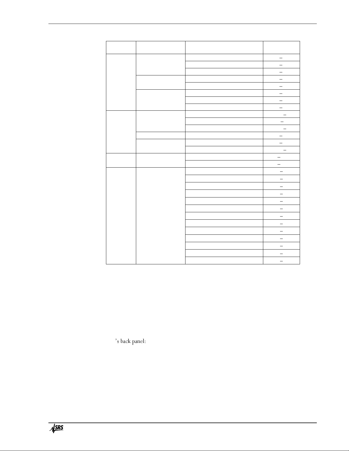
Standard calibration curves are included for the following sensors.
the range of the standard calibration curve; outside this range, no reading appears for the sensor. It
may be possible to obtain a larger range by uploading a custom calibration curve.
Page 19

Introduction 3
PTC10 Programmable Temperature Controller
Sensor
class
Manufacturer
Calibration
type
Range,
K
Diode
Scientific Instruments
Si410
1.0 450
Si430
1.0 400 Si440
1.0 500
LakeShore; Omega
DT-470 (=CY7)
1.4 475
DT-670 (=CY670)
1.4 500
Cryo-Con
S700
1.5 475
S800
1.4 385
S900
1.5 500
Ruthenium
oxide
LakeShore
RX-102A
0.050 40
RX-103A
1.2 40
RX-202A
0.050 40
Scientific Instruments
RO600
1.0 300
Cryo-Con
R400
2.0 273
R500
0.050 20
RTD
All
IEC751 (DIN43760)
48.15 1173.15
US
48.15 1173.15
Thermistor
Measurement
Specialties,
Inc.
(formerly YSI);
Omega
100
193.15 373.15
300
193.15 373.15
1000
193.15 373.15
2252
193.15 523.15
3000
193.15 523.15
5000
193.15 523.15
6000
193.15 523.15
10000 type B
193.15 523.15
10000 type H
193.15 523.15
30 k
233.15 523.15
100 k
233.15 423.15
300 k
298.15 423.15
1 M
298.15 423.15
Other resistive and diode sensors can be used with the PTC320, but require custom calibration
curves. For example, rhodium-iron, germanium, and carbon-glass sensors have too much sensorto-sensor variability to use a standard curve, and therefore must be custom-calibrated.
Connecting the sensor
The PTC320 has a 6-pin DIN socket that mates with standard 6-pin push-pull DIN plugs (i.e.
Digi-Key CP-1060-ND). This is the pinout of the socket, as it appears when looking at the back
panel:
1
5
4
2
6
3
Not connected
Excitation +Sense +
Ground
Excit
Page 20

Introduction 4
PTC10 Programmable Temperature Controller
chassis.
The PTC320 passes an excitation current through the attached RTD, thermistor, or diode, and
senses the induced voltage. For the most accurate results all sensors should be read with a four-wire
configuration, using separate sense and excitation leads. However, for convenience the PTC320
can also read sensors attached with only two leads.
To make a two-wire measurement, connect one end of the sensor to pin 1 (Excitation ) and the
other to pin 5 (Excitation +). An inaccuracy is introduced because the resistance of the leads affects
the measurement; however, some thermistors have such a high resistance that the lead resistance
may be negligible in comparison.
A four-wire measurement eliminates the effect of lead resistance. In the four-wire configuration,
two of the wires carry the excitation current, while the other two wires sense the voltage that the
current produces across the sensor. RTDs sold with four wires normally have two wires of one
color, both attached to one side of the RTD, and two of a different color attached to the other side.
In this case, the RTD should be wired to the PTC320 in one of the following two ways (assuming
the leads are white and black):
Pin 1
Pin 2
Pin 3
Pin 4
Pin 5
Option 1
White
White
Unconnected
Black
Black
Option 2
Black
Black
Unconnected
White
White
RTDs with two wires can be modified by connecting two additional wires, one on each side of
the sensing element and as close to the sensing element as possible.
The higher the resistance of a sensor, the more its leads pick up noise from ambient
electromagnetic radiation. The noise level of high-resistance thermistors in particular can often be
improved by using a shielded cable and connecting the shield to pin 3.
Excitation current
The excitation current provided to the sensor is automatically determined by the PTC320. For
resistive sensors, the current is determined by the type of sensor and the measurement range as
shown in the table below. When a diode sensor is in use, the card always produces a 10 µA
excitation.
Measurem ent
range
RTD
excitation
Therm istor
excitation
Diode
excitation
30
5 mA
200 µA
100
2 mA
100 µA
300
1 mA
50 µA
1 k
500 µA
30 µA
3 k
200 µA
20 µA
10 k
100 µA
10 µA
30 k
50 µA
5 µA
100 k
10 µA
3 µA
300
5 µA
2 µA
2.5 V ( )
1 µA
1 µA
10 µA
Excitation current produced by the PTC320
The thermistor excitation current results in about 1 µW of power being dissipated in the
thermistor at the high end of each measurement range. Therefore, if the dissipation constant of the
thermistor is above 1 mW/°C, the measurement error due to self-heating should be less than 1
mK.
Page 21

Introduction 5
PTC10 Programmable Temperature Controller
PTC321 RTD reader
Resistance temperature detectors (RTDs) use the resistance of a metal wire or film to indicate
temperature. RTDs are usually made of platinum which, being very non-reactive, produces sensors
with exceptional long-term stability. However, platinum RTDs are also expensive and have a
limited temperature range.
Typically, the resistance is measured by passing an excitation current through it and
measuring the resulting voltage drop. A four-wire RTD has two wires to carry the current and two
to measure the voltage. Negligible current flows through the voltage-measuring wires, ensuring
that the resistance of the wires does affect the measured voltage.
RTDs usually have the °C (IEC751
standard). The cient of 0.00392 °C is less common, even in America.
The PTC321 RTD reader reads up to four 100 ohm platinum RTDs with a 1 mA excitation
current. The current through the RTD can be reversed with each reading to null out parasitic
thermocouple voltages.
The PTC321 has a range of 10 , allowing it to read 100 European-type platinum RTDs
in the temperature range 215 to 850°C. RTDs with other base resistances can also be used, but
over a smaller temperature range.
The PTC321 is calibrated at ambient temperatures of 25 and 35°C. An on-board temperature
sensor continuously interpolates between these two calibrations to account for thermal drift of the
electronic components. Since the PTC10 enclosure is usually elevated 2 to 3 degrees above
ambient temperature, the accuracy of the PTC321 may be reduced if the ambient temperature rises
above about 32°C.
To further improve measurement stability, the PTC321 can control the main enclosure fan to
keep the card at a constant temperature (see the Channel.PCB button).
A narrow flange is available for the PTC321. With this flange mounted, the card can be plugged
into either slot 5 (normally occupied by the analog I/O card) or slot 6 (normally occupied by the
digital I/O card). Since all six slots of the PTC are identical except for their width, the I/O cards
can be arranged in any order as long as they fit into the slots. To order the narrow flange from SRS,
contact sales and ask for part number 7-01920-720.
Connecting the RTDs
RTDs are connected to the PTC321 with removable 5-pin, 3.5 mm terminal plugs (e.g.,
Weidmüller part number 169045). The supplied plugs use a tension clamp to hold the RTD wires.
To install the RTD wires:
1. Hold the plug such that the row of five small holes is on the right and the five larger holes are
on the left.
2. Each pair of holes is blocked by a metal clip. Place a small screwdriver into one of the small
holes and firmly push it into the narrow gap to the right of the clip. The screwdriver should
go in about half an inch and push the clip to the left.
3. The larger hole should open up. Place a stripped wire into the hole and remove the
screwdriver.
Plugs with screw clamps (e.g., nnect the
RTD wires to these plugs, but the wires often come loose, resulting in noisy temperature
measurements. The tension clamps are a little more difficult to install but produce a more reliable
connection.
Page 22
Introduction 6
PTC10 Programmable Temperature Controller
On each connector, the top two pins receive the resistance signal, the middle pin is a ground that
can be connected to a shield or left unconnected, and the lower two pins provide the excitation
current.
Commercial 4-wire RTDs usually have two wires of the one color connected to one end of the
resistive sensor, and two of a different color connected to the other end. There is normally no
shield. In this case, the RTD plug should be wired in one of the following ways (assuming black and
white wires):
Pin 1
Pin 2
Pin 3
Pin 4
Pin 5
Option 1
White
Black
Unconnected
White
Black
Option 2
Black
White
Unconnected
Black
White
If the plug is wired any other way, no reading appears when the sensor is plugged into the RTD
reader.
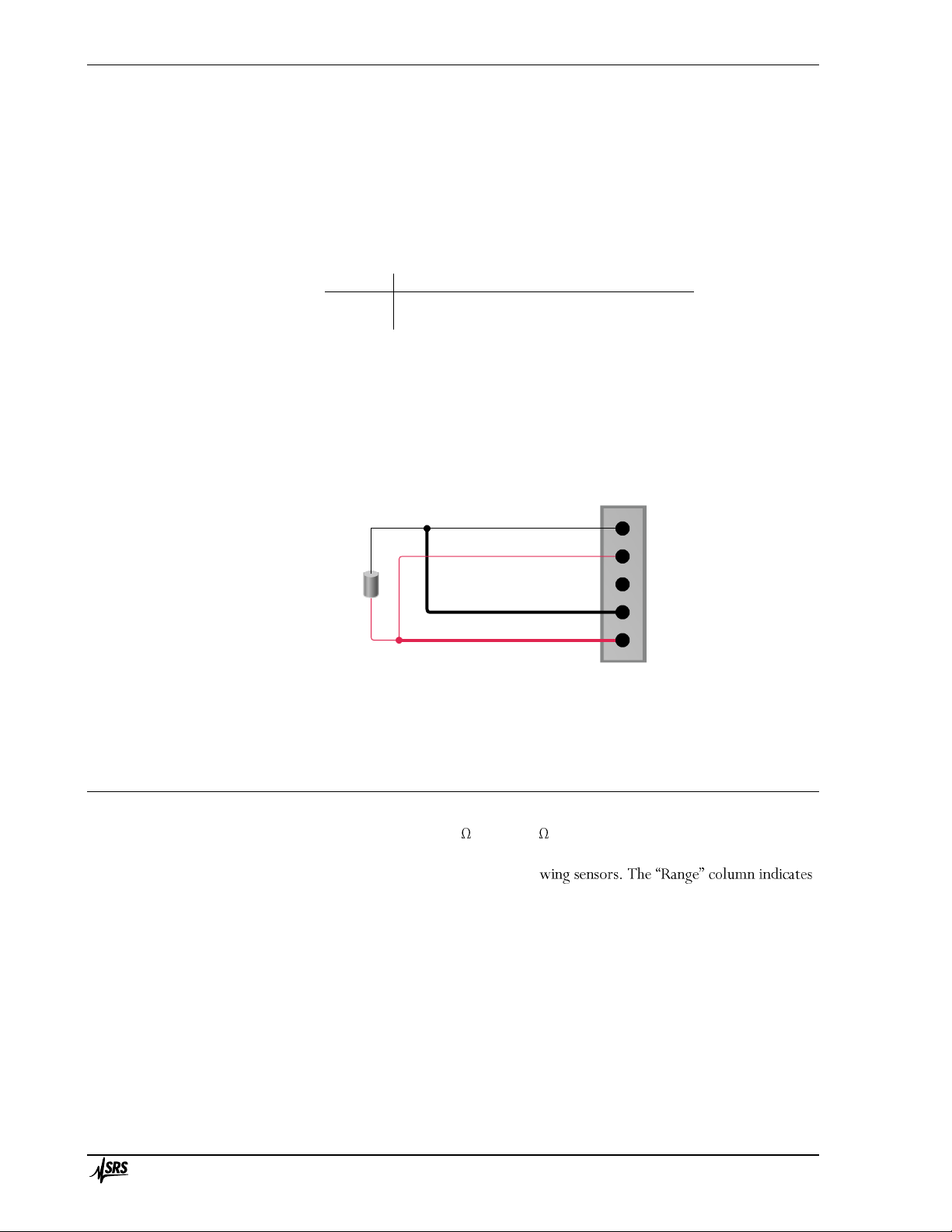
RTDs with two wires must be modified by soldering two additional wires to the existing wires,
one on each side of the sensing element and as close to the sensing element as possible. The diagram
below shows how to connect the wires to the PTC321.
Connecting a 2-wire RTD to the PTC321 RTD reader
PTC323 2-channel thermistor/diode/RTD card
The PTC323 is a two-channel, multi-range input card that can read a variety of temperature
sensors. It can read resistances between 1 and 2.5 M , and can also read diode temperature
sensors.
Standard calibration curves are included for the follo
the range of the standard calibration curve; outside this range, no reading appears for the sensor. It
may be possible to obtain a larger range by uploading a custom calibration curve.
Connect the two wires that
came with the sensor (thin lines)
to the Signal inputs
Solder two additional wires (thick lines)
to the sensor and connect them
to the Excitation inputs
RTD
sensing
element
Signal
Signal
Ground
Excitation
Excitation
Page 23
Introduction 7
PTC10 Programmable Temperature Controller
Sensor
class
Manufacturer
Calibration
type
Range,
K
Diode
Scientific Instruments
Si410
1.0 450
Si430
1.0 400 Si440
1.0 500
LakeShore; Omega
DT-470 (=CY7)
1.4 475
DT-670 (=CY670)
1.4 500
Cryo-Con
S700
1.5 475
S800
1.4 385
S900
1.5 500
Ruthenium
oxide
LakeShore
RX-102A
0.050 40
RX-103A
1.2 40
RX-202A
0.050 40
Scientific Instruments
RO600
1.0 300
Cryo-Con
R400
2.0 273
R500
0.050 20
RTD
All
IEC751 (DIN43760)
48.15 1173.15 US
48.15 1173.15
Thermistor
Measurement
Specialties,
Inc.
(formerly YSI);
Omega
100
193.15 373.15
300
193.15 373.15
1000
193.15 373.15
2252
193.15 523.15
3000
193.15 523.15
5000
193.15 523.15
6000
193.15 523.15
10000 type B (32.66 k at 0°C)
193.15 523.15
10000 type H (29.49 k at 0°C)
193.15 523.15
30 k
233.15 523.15
100 k
233.15 423.15
300 k
298.15 423.15
1 M
298.15 423.15
Other resistive and diode sensors can be used with the PTC320, but require custom calibration
curves. For example, rhodium-iron, germanium, and carbon-glass sensors have too much sensorto-sensor variability to use a standard curve, and therefore must be custom-calibrated.
Connecting the sensor
The sensors are connected via a 9-pin D-sub (DB9) socket that mates with any standard DB9
plug, such as Amphenol L717SDE09P with backshell 17E-1657-09. One plug and backshell is
provided with each PTC323. Here is a wiring diagram of the socket as it appears when looking at
the PTC10
Page 24

Introduction 8
PTC10 Programmable Temperature Controller
A four-wire connection is used so that the PTC323 measures the resistance of the sensor and not
the wires going to the sensor. The +I and I pins provide a small current and should be connected
to the temperature sensor with two wires, preferably a shielded twisted pair. The +V and V pins
measure the voltage produced across the sensor and should be connected to +I and -I as close as
possible to the sensor.
Resistive sensors: Four-wire resistive sensors usually have two wires of one color attached to
one side of the RTD, and two of a second color attached to the other side. Two wires of the same
co
wires of the other color should be connected to the V and I pins.
Two-wire sensors can be converted to four-wire sensors by soldering two additional wires to the
existing leads, one on each side of the sensing element and as close to the sensing element as
possible. Soldering is essential; the wires should not be connected to the sensor by pressure alone
(e.g. crimping or clamping), as any resistance within the joint becomes part of the measured sensor
resistance.
The higher the resistance of an RTD or thermistor, the more sensitive it is to ambient
electromagnetic noise and the greater the need for shielded cables.
Diode sensors: Diode sensors can be connected in either direction. If no reading appears,
change the current direction from Forward to Reverse.
Diode sensors are especially susceptible to electromagnetic noise because the diode rectifies any
noise picked up by the sensor leads, increasing the measured voltage. It may be necessary to place
the sample within an electromagnetically shielded enclosure and to put EMI filters not only the on
the sensor leads but also on all other leads entering the enclosure. The filters should be located at
the point where the wires enter the enclosure, and the enclosure itself should be grounded. D-sub
and circular connectors with built-in filters, as well as individual filters, can be obtained from
Spectrum Advanced Specialty Products. We have found their 4000 pF pi filters to be effective.
These filters include capacitors to ground, which should be connected either to the ground pin (pin
3) of the sensor input connector or to chassis ground.
AD590 sensors: The PTC323 can read AD590 sensors if the sensor is connected in series with a
2 k resistor as shown below. Note that the diagram shows the sensor connected to channel A, but
it can also be connected to channel B. The diagram shows the back of the DB9 connector, that is,
the side that you solder to, with pin 1 in the bottom-right corner.
sistors
have a TCR of about 100 ppm/°C, which means that the sensor reading will drift upward by about
30 mK for each 1°C rise in ambient temperature. Thermal drift can be reduced substantially by
AD590
+I
1
6
5
9
+V
+
Page 25
Introduction 9
PTC10 Programmable Temperature Controller
using a 5 ppm/°C resistor available from SRS; ask for part number 4-02502-457. For even better
stability, a 1 ppm/°C resistor such as the Riedon USR2G-2KX1, available from Digi-Key, can be
used. In any case, to minimize noise and drift, the resistor should be soldered directly to the pins on
the DB9 plug and covered up with the backshell.
Because AD590 sensors are highly sensitive to electromagnetic interference, the AD590 wires
and package must be shielded, with the shield connected to pin 3 of the DB9 connector.
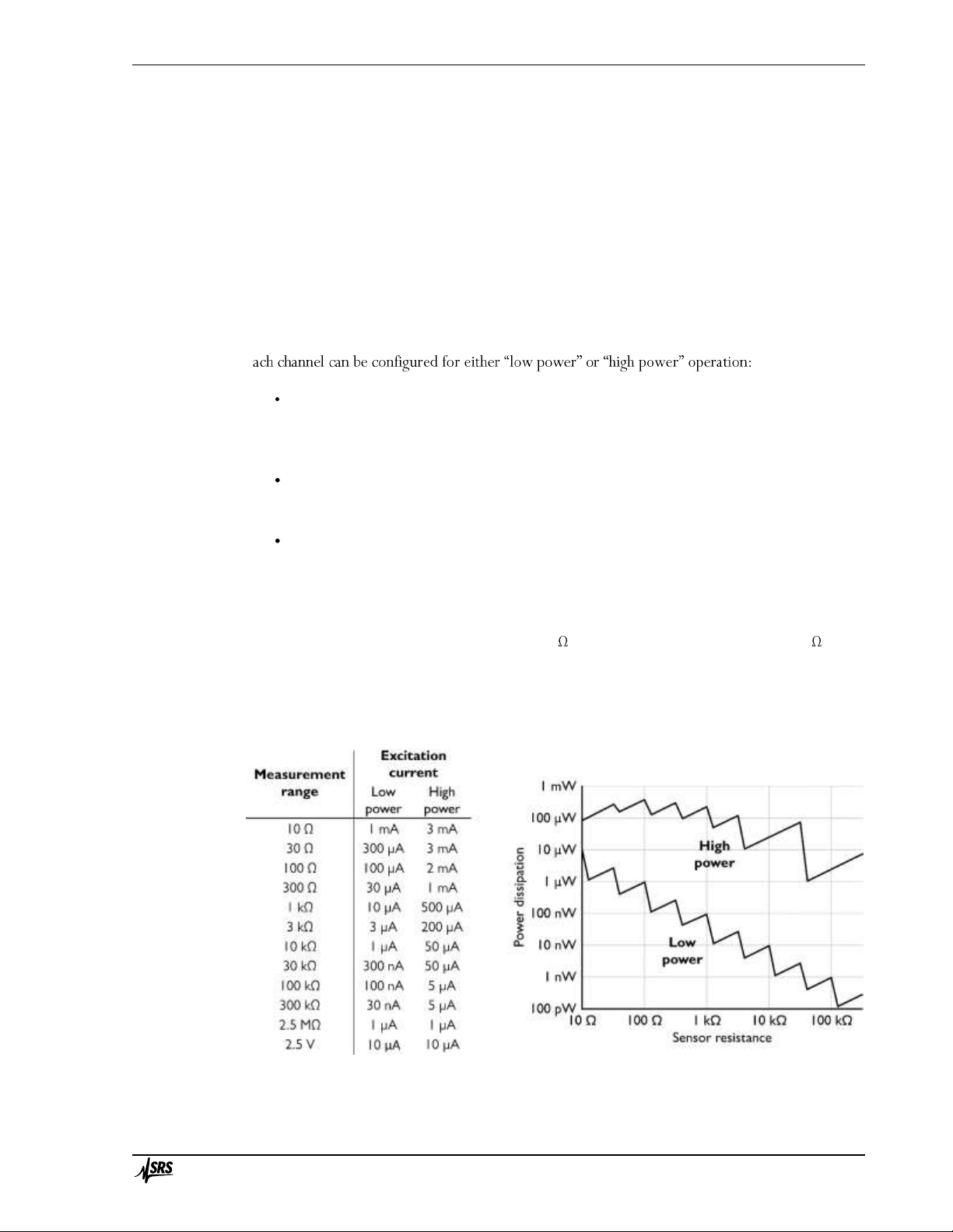
Excitation current
The PTC323 measures the resistance of the sensor by passing an excitation current through it.
The larger the excitation, the less noise the temperature reading will have. However, if the
excitation is too large it will heat the sensor and cause higher than expected readings. Therefore,
e
Low power: minimizes sensor heating. This option is mainly for use with thermistors in
cryogenic applications. To compensate for the fact that heat conductivity decreases (and
thermistor resistance increases) as the temperature approaches absolute zero, the amount of
power that the sensor dissipates decreases as the measurement range is increased.
High power: minimizes noise. Power dissipation is kept roughly constant as the
measurement range is increased. This option is for use with RTDs or with any kind of sensor
at non-cryogenic temperatures.
Auto power: uses low power if the sensor type is set to thermistor or ROX, or high power
if the sensor type is set to RTD.
The PTC323 has 12 measurement ranges. Within any given range, it generates a constant
excitation current as shown in the table below. Note that the range has to be greater than the
sensor resistance, so if the sensor resistance is 10 k , for example, the range should be 30 k .
For diode sensors the range is always 2.5V and the excitation current is always 10 µA.
The graph below shows how the amount of power dissipated by the sensor depends on the range
and power settings. Sensor heating (degrees above the ambient temperature) is proportional to
power dissipation.
Left: the amount of current passed through the sensor by the PTC10; right:
the amount of power that the sensor dissipates due to that current
Page 26
Introduction 10
PTC10 Programmable Temperature Controller
The table below shows some representative noise, electronic accuracy, and self-heating values for
free-standing sensors at room temperature. Note that the amount of self-heating can vary
dramatically depending on the thermal conductivity of whatever the sensor is attached to or
immersed in.
Noise
Accuracy
Self-heating
Low
power
High
power
Low
power
High
power
Low
power
High
Power
100 RTD
20 mK
0.8 mK
640 mK
40 mK
0.09 mK
100 mK
1 k thermistor
2 mK
0.08 mK
60 mK
3 mK
0.009 mK
40 mK
10 k thermistor
2 mK
0.02 mK
50 mK
2 mK
0.0009 mK
25 mK
100 k thermistor
9 mK
0.04 mK
220 mK
3 mK
0.00009 mK
2.5 mK
Noise, accuracy, and amount of self-
accuracy of the PTC10 immediately after calibration and does not account for self-heating or the accuracy
- above ambient temperature of a ~1 mm diameter sensor hanging
by its leads in still air (dissipation constant 1 mW/°C).
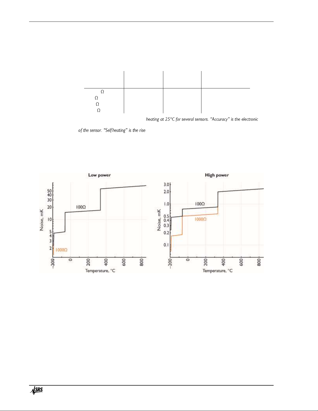
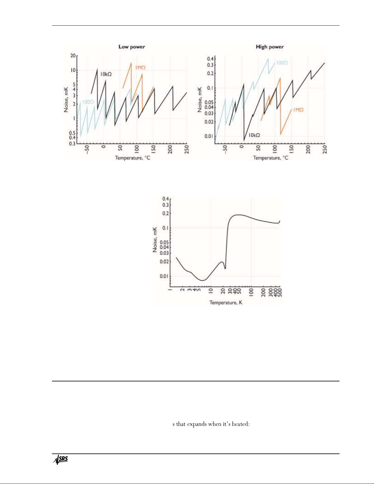
The graphs below show how electronic noise varies with temperature for several types of
sensors.
RMS noise levels for 100Ω and 1000Ω platinum RTD sensors as a function of temperature. At low power, the 100Ω
and 1000Ω sensors have about the same noise level.
Page 27
Introduction 11
PTC10 Programmable Temperature Controller
RMS noise levels for 100Ω, 10kΩ, and 1MΩ (at 25°C) thermistors as a function of temperature
RMS noise for DT-670 diode sensor as a function of temperature.
The direction of the excitation current can be set by the user to forward, reverse, or AC
(switching between forward and reverse with each sample). AC current is recommended for
resistive sensors to reduce noise and drift. AC current cannot be used with diode sensors.
PTC330 thermocouple reader
How thermocouples work
If the two ends of a metal wire are held at different temperatures, the electrons at the hot end
move faster than those at the cold end. Since the electrons are free to diffuse throughout the wire,
they behave somewhat like a ga the hot end of the wire develops a
lower density of electrons relative to the cold end. As a result, the hot end has a slight positive
Page 28

Introduction 12
PTC10 Programmable Temperature Controller
charge and the cold end a slight negative charge, producing a voltage difference. The exact voltage
depends on the temperature at each end and the composition of the wire.
A thermocouple has two wires that develop different voltages in response to a given temperature
difference. The wires are welded together at one end ) and the voltage difference
is measured at the other junction . If we know the cold junction temperature and if each
wire has a perfectly homogeneous composition, we can calculate the hot junction temperature.
Normally, we measure the cold junction temperature with another sensor such as an RTD or a
thermistor.
Thermocouple calibration tables generally assume that the cold junction is at 0 °C. Therefore, to
convert the thermocouple voltage to a temperature, to calculate what the
thermocouple voltage would be if the cold junction were at 0°C. For example, say a type K
thermocouple is used to measure the temperature of some liquid nitrogen. The thermocouple
reader measures a voltage of -6.829 mV and also determines that the cold junction is at 25°C. The
calibration table indicates that the voltage of a type K thermocouple at 25°C is 1.000 mV. So we
add 1 mV to the reading and look up the result, -5.829 mV, in the calibration table. The result is
the temperature of the inaccurately named -196°C.
Choosing a thermocouple
Thermocouples are inexpensive and can sense a wide range of temperatures, but without
frequent calibration they are accurate to no more than 1°C, partly because they tend to oxidize or
otherwise react with gases in their environment. Thermocouples made from thinner wires oxidize
more quickly and therefore exhibit more calibration drift than heavier-gauge thermocouples.
When selecting a thermocouple type, t s generally a tradeoff between sensitivity and
stability. That is, thermocouples that produce the largest voltages also have the most calibration
drift. With the excep he letters that describe thermocouples (E, J, K, etc.) appear
to be assigned in order of increasing long-term stability, with type C being the least stable and type
T the most. Therefore, if your application requires low noise, it might be best to choose type E; for
the best absolute accuracy, type T might be more appropriate.
Each PTC330 input supports one of the following thermocouple types:
Type E thermocouples have one chromel (90% nickel, 10% chromium) and one constantan
(60% copper, 40% nickel) wire. It has a large voltage change per degree (68 µV/°C), resulting in
excellent signal-to-noise ratio. However, its long-term stability is not very good. Type E
thermocouples are resistant to oxidation, but corrode if used in a vacuum or other reduced-oxygen
environment.
Type J thermocouples have one iron and one constantan wire. Above 500°C, oxidation of the
iron results in poor stability. This thermocouple is mainly used in legacy applications.
Type K thermocouples have one chromel and one alumel (95% nickel, 2% manganese, 2%
aluminum, 1% silicon) wire. With a wide temperatur s the most
popular type of thermocouple. Type K thermocouples are resistant to oxidation, but corrode if
used in a vacuum or other reduced-oxygen environment.
Type N thermocouples and 1% silicon) and one
and 0.1% magnesium) wire. They are designed for high stability,
especially at temperatures above 500°C. However, their sensitivity is low.
Type T thermocouples have one copper and one constantan wire. They are very accurate and
can be used in reducing atmospheres, but their temperature range is limited.
The following table summarizes some properties of thermocouples. Two temperature ranges are
given: the range that the thermocouple itself can withstand without losing its calibration, and the
built-in calibration tables, assuming that the cold junction
ng
Page 29
Introduction 13
PTC10 Programmable Temperature Controller
appears on the display and any feedback loops for which the thermocouple is an input do not
function.
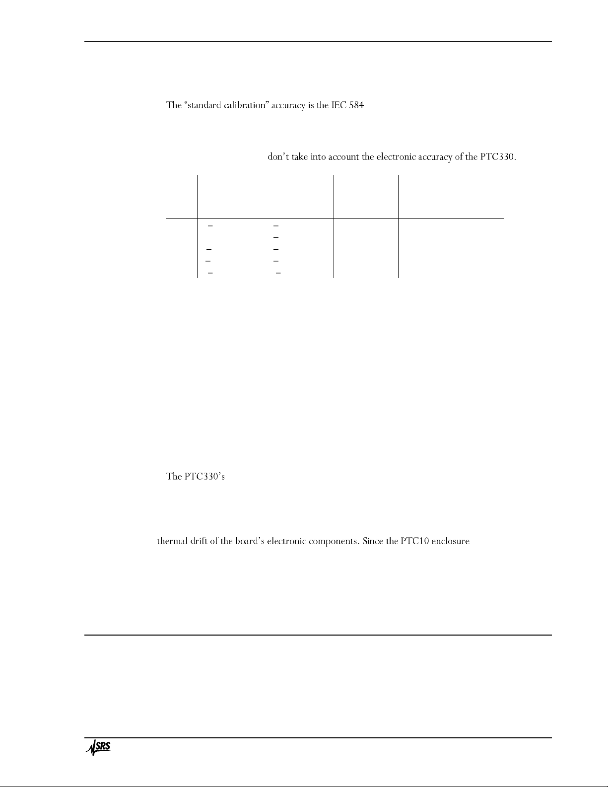
-2 standard for thermocouple-to-thermocouple
material variation. Not all commercial thermocouples may follow this standard; for example,
Omega specifies an accuracy of 2.2°C for its type J and K thermocouples. Greater accuracy is
possible if your thermocouple is custom calibrated. The accuracy values in this table only apply to
the thermocouple itself and
Tem perature range, °C
Accuracy
Type
Thermocouple
PTC10, cold
junction at 25°C
Sensitivity,
µV/°C at 25°C
Standard
calibration,
°C, at 0°C
Custom
calibration,
°C, <300°C
E
200 to 870
245 to 1025
60.9
1.7
1
J
0 to 760
185 to 1225
51.7
1.5
0.1
K
200 to1260
245 to 1395
40.6
1.5
0.1
N
270 to 1300
245 to 1325
26.5
1.5
T
200 to 350
245 to 425
40.6
0.5
0.1
Connecting thermocouples to the PTC330
The PTC330 thermocouple reader is factory-configured to read one of the above thermocouple
types. The thermocouple must be equipped with a miniature jack such as Omega part number
SMPW-J-M for type J, SMPW-K-M for type K, etc. The jacks on the PTC330 are color coded
according to the American (ANSI) color coding scheme, i.e. type J jacks are black, type K jacks are
yellow, etc. The colors may not conform to the standard colors used in other countries.
The thermocouple jacks are connected with thermocouple extension wires to a cold junction
block inside the PTC10. The cold junction temperature is measured with a platinum RTD
temperature sensor. The cold junction temperature is recorded so that if unexpected drift or other
artifacts appear in the thermocouple readings, it can be determined whether the artifacts are due to
erratic behavior of the cold junction. If readings are displayed in sensor units (see the
System.Other.Units button), the raw thermocouple EMFs are displayed in millivolts, not corrected
for the cold junction temperature, and the cold junction temperature is displayed in ohms.
inputs are optically isolated and the thermocouples can come in direct contact
with electrically live metal. In this case, however, the noise level and accuracy of the measurement
may be affected.
The PTC330 hardware is calibrated at ambient temperatures of 25 and 35°C. An on-board
temperature sensor continuously interpolates between these two calibrations to account for
is usually elevated 2
to 3 degrees above ambient temperature, the accuracy of the PTC330 may be compromised if the
ambient temperature rises above about 32°C.
To further improve measurement stability, the PTC330 can control the main enclosure fan to
keep the card at a constant temperature (see the manual entry for the Channel.PCB control).
PTC420 AC output card
The PTC420 AC output card has a solid-state relay that delivers mains current to the heater. It is
intended for control of large heaters including heating mantles, heating tape, and heating blankets.
The relay is either on or off; when on, the full AC mains voltage appears on the output. To vary the
output power, the PTC420 switches the relay on and then off once every 10 seconds (by default)
with a variable duty cycle.
Page 30
Introduction 14
PTC10 Programmable Temperature Controller
The card can deliver at most 5 A of current. If the resistance of the heater is too small, the card
delivers more than its rated current and may be shut down by its internal protection circuitry. In
some cases the card may be damaged. The minimum permissible heater resistance depends on the
AC line voltage as shown in the table below. The table also shows the maximum power that the
card can deliver.
Line
voltage,
V
Exam ple
locations
Min heater
resistance,
ohm s
Max power at
min heater
resistance, W
Max power
at heater
resistance R, W
100
Japan
20
500
10000 / R
120
Canada, US
24
600
14400 / R
220
Russia
44
1100
48400 / R
230
Europe
46
1150
52900 / R
240
China, Australia
48
1200
57600 / R
The total AC current delivered at any one time by the all the PTC420 cards in a single chassis
cannot exceed 10 A
PTC430 50 W DC output card
The PTC430 DC output card can deliver up to 50 W of power and is intended for precise
control of small heaters. The card offers two voltage ranges (50 V and 20 V) and three current
ranges (1A, 0.5A, and 0.1A). An auto-range feature continuously adjusts the current and voltage
ranges to the smallest values needed to achieve the power specified with the channel Hi Lmt
setting.
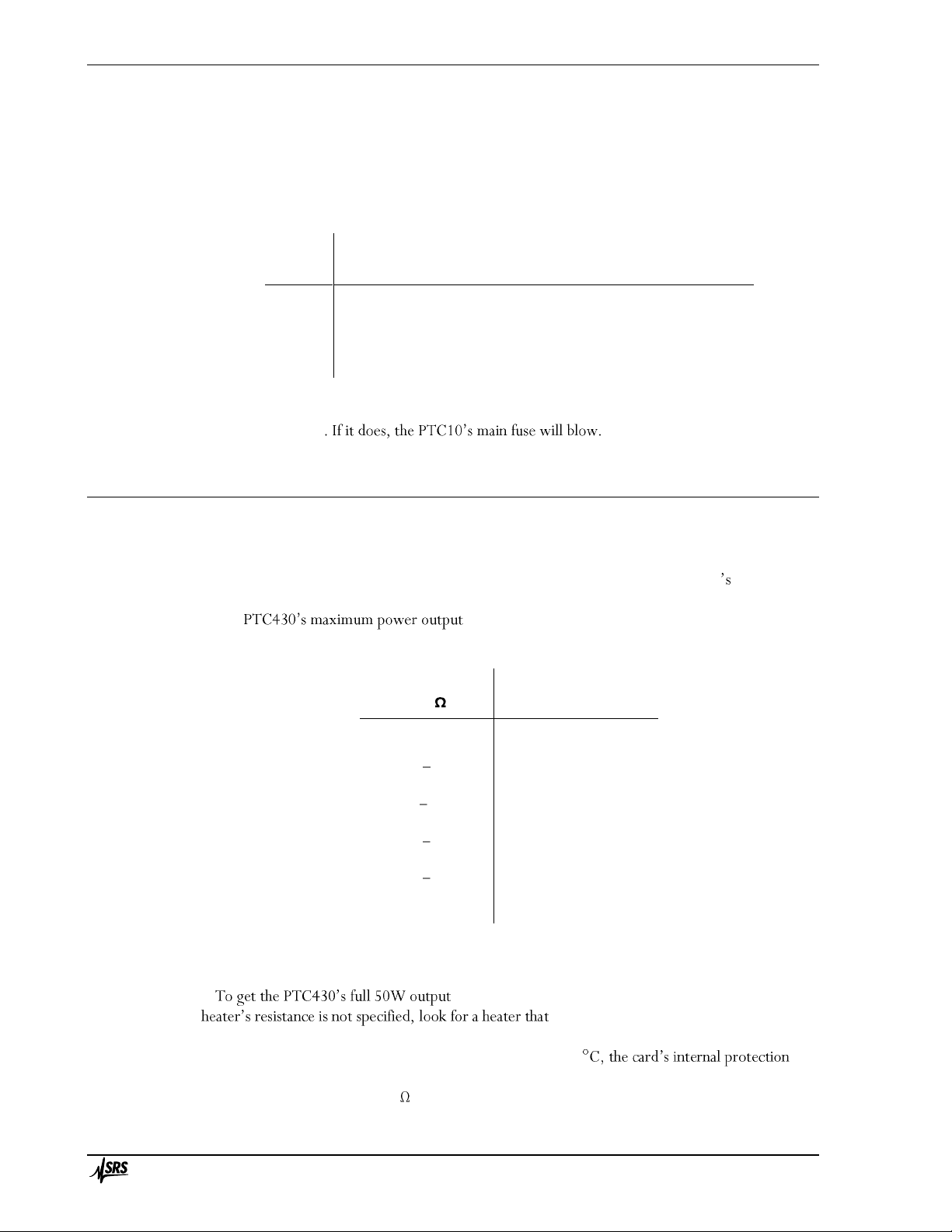
The depends on the resistance of the heater; see the table
below.
Heater resistance
(R),
Optimum
output
range
Maximum
power, W
> 500
50 V 0.1 A
2500/R
500
50 V 0.1 A
5
100 500
50 V 0.5 A
2500/R
100
50 V 0.5 A
25
50 100
50 V 1 A
2500/R
50
50 V 1 A
50
20 50
50 V 1 A
R
20
20 V 2 A
20
10 20
20 V 2 A
400/R
10
20 V 2 A
40
< 10
20 V 2 A
4R
Maximum output power and optimum output range as a function of
heater resistance
, the heater must have a resistance of 50 ohms. If the
produces about 265W at 115V or 1060W
at 230V.
If the heatsink temperature of a DC output card exceeds 60
circuitry shuts down the output. This is likely to occur if one of the 50V output ranges is used when
the heater resistance is under 20 ; if the ambient temperature outside the chassis is above 30°C; if
Page 31

Introduction 15
PTC10 Programmable Temperature Controller
and/or if the system fan is turned off or not working. If the heater
resistance is less than 20 , select the 20 V ranges to prevent thermal
shutdown.
The temperature of the heatsink can be monitored by setting the System.Display.Monitors
PCB temperature display
should appear on the Select screen directly underneath the current value of the DC output card. If
the temperature
If the 50 V 1 A range is used and the average heater resistance is less than 65 , up to three DC
output cards can be installed in a single chassis and run at full power simultaneously. If four DC
output cards are installed and the average output current at any given moment exceeds 0.8A, a
system reset may occur to protect the power supply from overload.
If any other range is used or the average heater resistance is greater than 65 , up to four DC
output cards can be installed in a single chassis and run at full power.
Hardware faults
The PTC430 continuously monitors for unsafe operating conditions. If such a condition occurs
and persists for more than 2 seconds, the In addition, one of the
following error messages appears in a pop- :
Ground fault: on, and the current s
positive terminal is not the same as the current flowing into the negative terminal. This error
can occur if one of the leads is shorted to an external ground.
Unexpected output current off, but current is flowing into
the negative terminal anyway. This error may indicate that the heater is shorted to a power
source other than the PTC430. It can also i
circuitry.
DC output card overheated: Either the resistance of the heater is too low; the positive
and negative terminals are shorted to each other
off; or the chassis fan is no longer functioning. Try reducing the maximum output voltage or
current, and make sure the front panel fan is running.
To re- key, then
re-enable the outputs by pressing the Output Enable key twice.
PTC431 100W DC output card
The PTC431 DC output card can deliver up to 100 W of power and is intended for precise
control of small heaters. The card offers two voltage ranges (50 V and 20 V) and three current
ranges (2A, 0.6A, and 0.2A). An auto-range feature continuously adjusts the current and voltage
ranges to the smallest
setting.
The 20V range can be used to limit the output voltage for safety purposes. Selecting this range
does not otherwise affect the performance of the card. On the other hand, the 0.6A and 0.2A
current ranges offer lower noise levels and are intended to be used when very precise temperature
control is needed.
The maximum power that the PTC431 can deliver depends on the resistance of the heater as
shown below.
Page 32

Introduction 16
PTC10 Programmable Temperature Controller
Maximum output power as a function of output range and heater resistance
at 230V.
circuitry shuts down the output. This is likely to occur if the heater resistance is under 10 ; if the
ambient temperature outside the chassis is above 30°C; and/or if the system fan is turned off or not
working. The PCB temperatures can be monitored by going to the System screen and setting the
Monitors control to Show.
Although up to four PTC431 cards can be installed in a chassis, only two can be run at full power
at any given time. If more than two PTC431 cards are installed, their output should be limited to
half their maximum value, either by using the 20V range or by setting the upper limit to 50W.
Hardware faults
The PTC431 can detect certain unsafe operating conditions. If such a condition occurs and
-enable the output,
disable all outputs by pressing the Output Enable key, then re-enable the outputs by pressing the
Output Enable key twice). In addition, one of the following error messages appears in a pop-up
Measured heater current differs from desired value: The ,
and the current at the positive terminal differs from the desired current by more than 0.25A.
This error can occur if the card is out of calibration. It can also mean that the card has been
damaged and is no longer capable of correctly regulating its output current or of producing
its rated output current.
Current at + and heater terminals is different , and the
current at the positive terminal differs from the current at the negative terminal by more
than 0.25A. This error can occur if one of the leads is shorted to an external ground.
Output is off but heater current was detected: current is flowing into the negative
. This error may
indicate that the heater is shorted to a power source other than the PTC10. It can also
i
Output card overheated: Either the resistance of the heater is less than 10 ohms; the
positive and negative terminals are shorted to each other; the ambient temperature is too
Page 33

Introduction 17
PTC10 Programmable Temperature Controller
or current, and make sure the front panel fan is running.
PTC440 TEC driver
The PTC440 includes a current source to drive a thermoelectric cooler and a sensor input for a
thermistor, RTD, or IC temperature sensor. The card has a single 15-pin D-sub connector for both
sections. The pinout and wiring diagram are shown below. Only pins 1 and 3 need to be connected
to power a TEC device, and only pins 8 and 14 need to be connected to read a temperature sensor.
The other pins are optional.
TEC driver section
A thermoelectric cooler (TEC), also referred to as a Peltier device, is a solid-state electric heat
pump that can both heat and cool, depending on the direction of current flow. Thermoelectric
coolers are generally used for precise temperature control of small objects in the range of -100
100°C.
With its high-current, low-voltage output, its ability to change the direction of current flow, and
circuitry to protect the TEC from excessive voltages, the PTC440 is primarily intended to drive
TEC devices. However, it can also drive low-resistance (optimally 2.4 ohm) resistive heaters. In
this case, the lower output limit should be set to 0 A and the heater should be connected to pins 1
and 3.
If the TEC is unplugged while current is flowing, or if the current is turned on when no TEC is
is
feature ensures that the voltage between the output terminals is always zero when a TEC is plugged
in. A nonzero voltage would produce a destructive current spike when the TEC is plugged in.
Therefore, if the PTC440 does not produce any output current, turn the current off and back on
three times or setting the output
value to zero with the Channel.value control.
Connecting the TEC
Connect the + and leads of the TEC to pins 1 and 3, respectively. Pins 2 and 4 can also be
connected to reduce contact resistance.
The PTC440 is a current source, that is, it has direct control over the current that passes through
the TEC but not the voltage. Since thermoelectric coolers are easily destroyed by both voltages and
currents even slightly above their rated maximum, the PTC440 provides a voltage input (Vmon) to
Page 34

Introduction 18
PTC10 Programmable Temperature Controller
monitor the TEC voltage. The connections for this input are the TEC sense + and TEC sense
pins. If these leads are connected to the TEC + and leads, as close to the TEC as possible, Vmon
shows the voltage across the TEC. If the leads are not connected, Vmon shows the voltage at the
.
If only a small current passes through the TEC even at its maximum voltage, the TEC may have
been damaged by excessive current or voltage.
Maximum TEC voltage
The TEC driver has four voltage ranges: 3, 6, 9, and 12V. In general, the lowest possible voltage
range should be used; besides potentially damaging the TEC, the larger voltage ranges create excess
heat inside the PTC chassis and ca
However, when selecting a voltage range, it's important to account for the resistance of the wires
you've used to connect the TEC. This resistance can significantly reduce the voltage available to the
TEC. For example, if the wires have a resistance of 0.5 ohms and a 5A current is flowing through
them, the wires will reduce the available voltage by 2.5V. Therefore, if the 3V range is selected,
the maximum voltage across the TEC will only be 0.5V. If the TEC sense leads have been
connected, this is the maximum voltage that will appear in the Vout display.
To minimize such voltage losses, heavy-gauge wires should be used to connect the TEC. Standard
DB-15 cables in particular should not be used because their thin wires absorb most of the PTC440's
output power.
The Vmon channel has a voltage limit, Vmax. If the voltage at the TEC exceeds Vmax, the
PTC440's output is shut off. The output will remain disabled until it is set to zero using either the
Output Enable key or the If the sense leads have been
connected, the lead resistance does not have to be taken into account when setting Vmax.
In some cases, the output may exceed Vmax every time the PID feedback is enabled. To avoid
this, temporarily set the ramp rate to a low value (i.e. 1 °C/s) when enabling the feedback.
Temperature input section
The PTC440 has a sensor input that can read thermistors, RTDs, AD590, and
LM135/LM235/LM335 temperature sensors. t is not intended for
precision applications and should only be used when temperature stability of ~0.1°C is acceptable.
For more demanding applications the sensor should be read with a dedicated input card such as the
PTC320 (for thermistors, RTDs, and diodes), PTC321 (for 100 RTDs only), or PTC330
(thermocouples). These cards provide lower noise and greater accuracy than the PTC440.
Connecting the temperature sensor
RTDs: 4-wire RTDs should be used to ensure accuracy. Two of the wires are normally white
and are connected to one end of the resistive sensor, while the other two are black, red, or yellow
and are connected to the other end. There is normally no shield. In this case, the RTD should be
wired in one of the following ways (assuming black and white wires):
Pin 7
Pin 8
Pin 14
Pin 15
Option 1
White
Black
White
Black
Option 2
Black
White
Black
White
Thermistors: Two-wire thermistors should be connected to pins 8 and 14.
Page 35

Introduction 19
PTC10 Programmable Temperature Controller
LM135/LM235/LM335: The LM135, LM235, and LM335 are integrated circuit temperature
sensors. If an excitation current between 400 µA and 5 mA is passed through the sensor, the
voltage drop across the sensor is 10 mV/K. The three models have different temperature ranges,
with the LM135 having the largest range and the LM335 the smallest. For the best possible
accuracy the sensors can be connected in a 4-wire configuration, just like an RTD. However, it is
more common to connect the device in a 2-wire configuration, leavings pins 14 and 15 of the
PTC440 unconnected. The first row of the table below lists the four sensor input pins on the
s show which leads of the LM135/235/335
should connect to those pins.
Pin 7
Pin 8
Pin 14
(optional)
Pin 15
(optional)
8-pin SOIC
Pin 8
Pin 4
Pin 8
Pin 4
Other packages
+ +
AD590/AD592: The AD590 and AD592 are an integrated circuit temperature sensors. When a
/K flows
through the device. The two models have different packages and temperature ranges, with the
AD590 having a range of -55 150°C and the AD592 a range of -25 125°C. The AD590/592
can be connected in a 2- or 4- wire configuration as shown in the table below. For the 2-wire
configuration, leave PTC440 pins 14 and 15 disconnected.
Pin 7
Pin 8
Pin 14
(optional)
Pin 15
(optional)
8-pin SOIC
Pin 2
Pin 3
Pin 2
Pin 3
Other packages
+ +
Sensor excitation current
The excitation current provided to resistive sensors can be set to 10 µA, 100 µA, 1 mA, or auto.
In auto current mode, the sensor resistance is continuously monitored and the excitation current is
adjusted whenever the sensor resistance rises above or drops below the levels shown in the table
ion when a diode sensor is in use, or 1
mA when an LM335 or AD590 sensor is in use.
Sensor
resistance
Excitation
current
<2 k
1 mA
1 20 k
100 µA
>10 k
10 µA
TEC driver (for resistive sensors only)
Note that the resistance ranges overlap; if the sensor resistance is between 1 and 2 k , for
example, the TEC driver can use either 1 mA or 100 µA excitation. If possible, the excitation
current is kept at its previous value.
A slight temperature glitch may occur when the PTC440 switches from one range to the next. If
these glitches could disrupt your experiment, set the excitation current manually.
Page 36

Introduction 20
PTC10 Programmable Temperature Controller
A/D rate
Some TECs are capable of very fast response rates. If the temperature of your TEC changes very
quickly (on the order of 1 second) when a current is passed through it reduce
the system A/D rate (set with the System.Other.A/D rate command) from its default 100 ms to
50 ms. Operating the PID feedback loop at a faster rate allows it to more precisely control the
system temperature and, therefore, results in a more stable temperature.
PTC510 analog I/O card
This card is included as standard equipment and fits in either of the two narrow I/O card slots.
Each of its four channels can be either an input (±10V, 24-bit ADC) or an output (±10V, 16-bit
DAC). Each channel has a red back-panel LED that lights up when the channel is an output.
The analog I/O channels can be used as PID inputs or outputs. Since each channel can only
connected to an external amplifier.
PID feedback appear on the Channel Setup screen. The corresponding remote
available and the PID feedback loop is disabled. Instead, controls and remote instructions for an
alarm, lowpass filter, difference filter, time derivative, and offset/gain calibration appear. These
controls disappear, the remote instructions are not available, and the functions are disabled when
the channel is an output.
PTC520 digital I/O card
This card is included as standard equipment and fits in either of the two narrow I/O card slots,
although for compatibility with should be installed in slot 6. It offers four
relays, each capable of passing up to 5A of current. It also has eight isolated TTL I/O lines on a 25pin connector compatible with the pinout of the standard PC parallel port. The TTL lines can
be used as inputs or outputs, but all eight must have the same direction.
The relays are hosted on a single 12-pin pluggable terminal block. The four rel
(comm state when the
PTC is turned off, when its outputs are not enabled, or when the relay is set to 0. In this state, the
pin a
1 and the outputs are enabled, the relay is activated: the
The relays appear on the PTC10 display as a single 4-bit integer value between 0 and 15. If no
relays are activated, the value is 0. Each relay, if activated, adds the following to the displayed
value:
Relay
A
B
C
D
Value
1
2
4
8
Therefore, if the relay channel 2 , only relay B is activated. If the channel read 6 , relays B
and C are activated. Conversely, setting the relay channel to 6 activates relays B and C, and
Page 37

Introduction 21
PTC10 Programmable Temperature Controller
deactivates the other relays. To set an individual relay from a macro or serial port without affecting
the states of other relays, use a bitwise operator; for example, the remote command
relays |= 4
activates relay C, while the remote command
relays &= 11
remote commands.
The eight TTL lines are located on a standard 25-pin D-sub connector with the following pinout
(the pin numbers are usually printed next to the pins on D-sub connectors):
1 Unconnected
2 D0
3 D1
4 D2
5 D3
6 D4
7 D5
8 D6
9 D7
10 +5V
11 +5V
12 Gnd
13 Unconnected
14 Unconnected
15 Unconnected
16 Unconnected
17 Unconnected
18 Unconnected
19 Gnd
20 Gnd
21 Gnd
22 Gnd
23 Gnd
24 Gnd
25 Gnd
ground of whatever system the digital I/O is interfaced with. Alternatively, if the digital I/O lines
are configured as inputs, a +5V pin can be shorted to any of the inputs D0 to D7 to pull them high,
-limited with 4.7
k resistors and are not intended to power a remote system.
The status of the eight digital I/O lines is reported on the PTC10 display as a single eight-bit
integer value. Each I/O line is assigned an integer value as shown in the following table:
Bit
D0
D1
D2
D3
D4
D5
D6
D7
Value
1
2
4
8
16
32
64
128
example, if only bits D1 and D3 are set, a DIO value of 2 + 8 = 10 is displayed.
Using the remote interface, macros can be defined that associate the digital I/O lines with most
functions of the PTC10. The remote interface provides bitwise operators to set and query the
relays and digital I/O lines.
Page 38

Introduction 22
PTC10 Programmable Temperature Controller
The DIO lines can be used to pass a single, 8-bit value into or out of the PTC. The PTC treats
the DIO like any other channel; for example, its value can be plotted or used in a PID feedback
loop.
Virtual channels
The digital I/O card has three virtual channels with the default names V1, V2, and V3. These
channels are not connected to any physical inputs or outputs. Instead, macros or remote commands
can assign arbitrary values to these channels, or the channels can automatically follow the value of
another channel. Like , the values of virtual channels can be plotted on the Plot
screen, displayed on the Numeric screen, and logged to RAM and USB.
Each virtual channel can either an input or an output (see the Channel.IO Type button)
input, a virtual channel can follow the value of another channel (see the Channel.Follow button),
and its value can be modified by applying a lowpass filter, subtracting a difference channel, taking
its derivative with respect to time, or applying offset/gain factors. By doing these calculations on a
virtual channel that has been configured to follow a sensor input (instead of doing them directly on
the sensor input channel), the raw sensor input is preserved and can still be viewed.
If the virtual channel is an output, it has a PID feedback loop that can be used for cascade control
(see the description of the Channel.PID.Casc button in the Operation section). Unlike other
with the Output
Enable button. However, virtual PID feedback loops do
are disabled.
When the value of a virtual channel is changed by a macro or from the front panel, the new value
does not become effective until an ADC conversion occurs. Therefore, if a macro sets the value of a
virtual channel and then immediately reads the value back, the old value may be returned.
Page 39

Operation 23
PTC10 Programmable Temperature Controller
Operation
Page 40

Operation 24
PTC10 Programmable Temperature Controller
Turn the instrument on
Plug the PTC10 in and turn it on with the power switch located next to the AC power inlet.
If the PTC10 does not turn on, a fuse may have blown. Check the fuse holder just above the
on/off switch.
If the instrument turns on but does not respond to button or touchscreen presses, the most likely
cause is that the ground prong of the electrical socket is not connected to ground. A three-prong
plug must be used and all three prongs must be connected.
The Select screen
Each of the green buttons on this screen represents one I/O channel. The buttons are arranged in
roughly the same order as the connectors on the back of the PTC10. Each button shows the
ected, the value may be blank.
Some of the buttons represent internal data channels. In the figure above, for example, the
channels that can be used for c isplay heater current, voltage, and
bold if the channel uses a custom calibration table.
Touch one or more buttons to select which channels to show on the Numeric, Plot, and Channel
screens.
Configure the sensor inputs
thermistor/diode/RTD input card, it may be necessary to
select the sensor type and calibration curve.
1. Select one or more inputs on the Select screen.
Page 41

Operation 25
PTC10 Programmable Temperature Controller
The top of this screen has one
tab for each selected channel. Touch one of the tabs to display the settings for that channel.
3. T
etc.)
5. In the
If the sensor reading does not appear
The sensor reading is blank whenever it falls outside the limits of the calibration data or input
hardware. This normally occurs when no sensor is connected, but can also occur if the sensor is
incorrectly configured. In this case, try the following steps:
1. Ensure that the sensor is correctly connected. Thermistors and RTDs should normally be
connected with four wires. Thermocouples and diodes must not be connected backwards.
2. Measure the resistance of the sensor with an ohmmeter to ensure that one of the wires is not
broken.
3. Bring up the channel setup screen for the input channel and check the following settings:
Sensor: must agree with the type of sensor that is in use.
Range: set to Auto or, if a fixed range is selected, ma
resistance.
Current: Forward, Reverse, or AC. If the current is off, no sensor reading will appear.
Cal Type: must agree with the type of sensor that is in use.
Cal R0: for RTDs only; must agree with the type of sensor that is in use.
appear in ohms or volts instead of degrees. Is the value correct?
5. If nce or voltage is
within the range of the calibration table.
instead connect a resistor of about the same value to the PTC10. If the reading is still
incorrect, the unit may need to be returned to SRS for recalibration.
Plot data
To plot data on-screen:
1. On the Select screen, touch the buttons to highlight the .
Once the Plot screen is showing, press the Plot key repeatedly to cycle between four screen
arrangements:
One plot for each channel
All channels on a single plot
Ponytail plot: all channels on a single plot, offset such that each channel starts at zero
Custom: channels are assigned to plots with
described on page 65.
Page 42
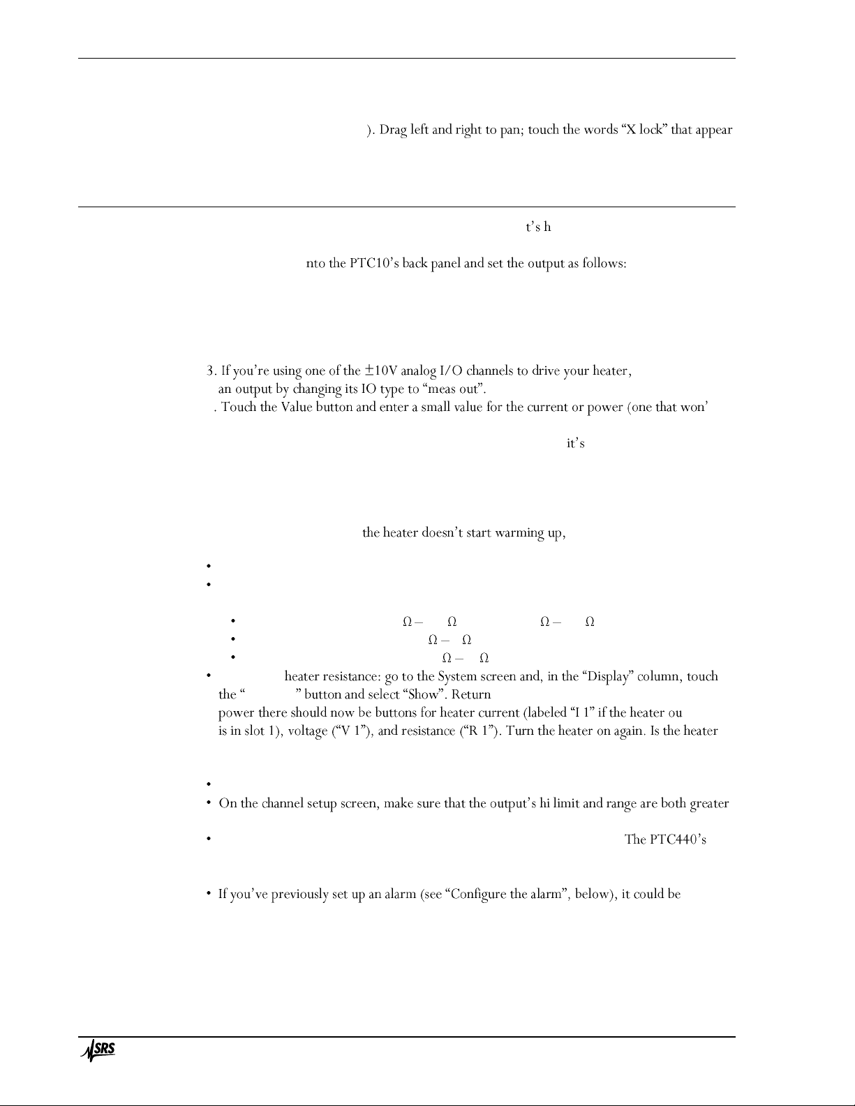
Operation 26
PTC10 Programmable Temperature Controller
Touch anywhere within the right half of the plot to zoom in. To zoom out, touch the left half of
the plot (but not left of the Y axis
in the bottom-left corner of the screen to return to viewing real-time data.
Test the outputs
Before trying to run a PID feedback loop for the first time, i elpful to verify that your heater
is working by setting its current or power to a low value and seeing if any current flows. To do
this, plug your heater i
1. Enable the outputs by pressing the Output Enable key twice. The red Output Enable light
should turn on.
2. Select the output channel on the Select screen, then press the Channel key to display the
channel setup screen.
make the channel
4 t
damage your system).
5. The Value button should display the value that you entered. If blank or displays zero, the
PTC is not detecting the heater.
6. Verify that your heater is warming up.
7. To turn the current off, touch the Off button on the channel setup screen.
If the Value button is blank or try the following:
Verify that the heater leads are not shorted to ground or to each other.
If the heater is resistive, unplug it from the PTC10 and measure its resistance with a
multimeter. Make sure that the resistance is appropriate for the output card:
PTC420 AC output card: 24 300 (120VAC), 46 600 (230VAC)
PTC430 50W DC output card: 1 1k
PTC431 100W DC output card: 10 1k
Display the
Monitors to the Select screen. Underneath the heater
tput card
resistance the same as what you measured with a multimeter? Is the voltage or current at the
maximum that the output can produce?
Verify that the PID mode is set to off.
that the output value that you entered.
If the output is a PTC440 TEC driver, disable and re-enable the outputs.
output is automatically disabled if you try to output a current when no TEC device is
connected, or if the voltage exceeds the Vmax setting.
disabling
the output. For example, if you move a sensor from one input to another, remember to
disable the alarm on the old input.
Page 43

Operation 27
PTC10 Programmable Temperature Controller
Set the data logging rate
By default, the PTC10 records ten data points per second . To change this
rate, press the System key on the
and select from the list of available options
The log interval determines the maximum l
plot screen. The PTC10 stores up to one million data points for each channel in its on-board
memory, while older data points are erased. At the default logging interval of 0.1 seconds, the
graph can display about the last 27 hours of data. If the logging interval is 1 second, up to
11 days of data can be displayed. The logging interval has to be set before the data is acquired; all
on-board data is erased when the logging interval is changed.
The log interval also determines how much time a single log file can cover; see the next section
below.
It s also possible to assign a different log interval to each channel; see the description of the
Channel.Logging control on page 65.
Save data to and retrieve data from a USB memory device
A USB memory stick can be used to keep a permanent record of logged data.
Data is logged to an ASCII file. The default name of the log file is \Log\00\Log00.csv (the top-
front panel). The file is an ASCII CSV
(comma-separated value) file that can be read with spreadsheet software.
The maximum size of the file is 2GB for FAT-formatted USB devices or 4 GB for FAT32 devices.
The file can reach this size in as little as 6 days, but more typically it should take about 30 days.
When the file fills up, Log00.csv is closed and the PTC10 automatically begins writing data to a
new file named Log01.csv. If Log99.csv fills up, the PTC10 begins logging to a new directory
\Log\01 -level directory name).
Save data to a USB device
1. Plug the USB memory stick into the port on the back of the instrument.
ars
on-screen. The message stays on-screen for several seconds while the log files are opened,
then the message disappears.
3. Look for a small, dark red circle in the upper-right corner of the screen. This is the USB
logging indicator. Touch the circle. When it turns light red, the PTC10 is saving data to the
USB device.
4. Before turning the instrument off or removing the USB device, touch the USB logging
indicator again and wait for it to turn dark. This step is very important to prevent damage to
the USB device. If this step is skipped, the USB device should be re-formatted in a PC before
using it again.
View saved data on a PC
A software package that can be downloaded from the SRS website (www.thinksrs.com, click
Downloads > Software) includes a program that plots log files. No installation is required; just
double-
Page 44

Operation 28
PTC10 Programmable Temperature Controller
Interface with a computer
front panel, has -232, USB, GPIB, and Ethernet interfaces
The USB port uses an FTDI USB chip. If the PC asks for a driver, follow these instructions:
Install the USB driver for Windows PCs
1. Download and install the appropriate FTDI Virtual Com Port (VCP) driver from:
http://www.ftdichip.com/Drivers/VCP.htm
2. Optional: the default baud rate for the FTDI driver is 9600. For faster communication,
change the baud rate to 230400 on both the PC and the PTC10. On the PTC10, press the
Setup key, touch the On the PC,
setting, open the Device Manager and expand the Ports line. Plug the PTC10 into the PC
and look for a new port to appear. Double-click that port, select the Port Settings tab, and
3. The PTC10 should now appear as a COM port on your computer, and your programs can
use the USB connection in the same way that they use an RS-232 connection.
Read data from the PTC10
All RS-232, GPIB, USB, and Ethernet messages sent to the PTC10 must end with a linefeed
\ ntil the linefeed is
received. Instructions are not case-sensitive.
The most recent value (i.e., the value read at the most recent ADC conversion) of a single
channel can be queried by sending the name of the channel, followed by a question mark.
3A?
29.9313
the command:
Out1?
0.00000
The most recent value of all channels can be retrieved with a single getOutput instruction (the
question mark is optional in this case):
getOutput?
0.000000, 0.000000, 29.98424, 25.86019, 27.49236, NaN, 27.45483,
NaN, 268.9367, NaN, NaN, 0.000000, 10.04576, 10.04574, 10.04572,
NaN, NaN, NaN, 0, 0
Sensors that are disconnected or out of range (not a number). To
determine the order of the channels in the getOutput response, send the getOutputNames query:
getOutputNames?
Page 45

Operation 29
PTC10 Programmable Temperature Controller
Out 1, Out 2, 3A, 3B, 3C, 3D, Cold J 3, 4A, 4B, 4C, 4D, 5A, 5B,
5C, 5D, V1, V2, V3, DIO, Relays
This order does not change unless I/O cards are added, removed, or rearranged.
A third option for reading data is the getLog instruction, which returns the latest data point
written to the log. By default, a logged value is the average of ten ADC conversions. Therefore the
values returned by getLog are not as noisy as the values returned by the getOutput and <channel>?
instructions, both of which return the result from the most recent ADC conversion only. In
addition, getLog makes it easier to retrieve data acquired at consistent time intervals. For example,
begin by sending this
getLog "3A", last
27.53936
Note that the channel name must be in quotes if it contains a space. Next, send the following
command:
getLog "3A", next
27.57375
Each time
then returns the new data point.
Control a temperature
The PTC10 can control the temperature of one or more external devices. Each device must
include a heater or cooler, and a temperature sensor that monitors the temperature of whatever is
being heated or cooled.
-integral-differential (PID) feedback
algorithm that can monitor a temperature reading and determine how much power to send to the
heater or cooler. The algorithm uses a set of three gain factors to determine how much and how
quickly the heater or cooler power should be adjusted when the temperature deviates from its
desired value. These gain factors must be properly set before the PTC10 can control the
temperature of your system.
Start by plugging the heater and
must be in thermal contact with the heater the better the thermal contact is, the more precise
the temperature control will be.
Enable the lowpass filter
Adding a lowpass filter to the temperature input usually improves feedback performance. On the
Select screen, touch the buttons for the heater output and the sensor input that you plan to use,
making sure that they and no other channels are highlighted. er
2 thermocouple input
Page 46
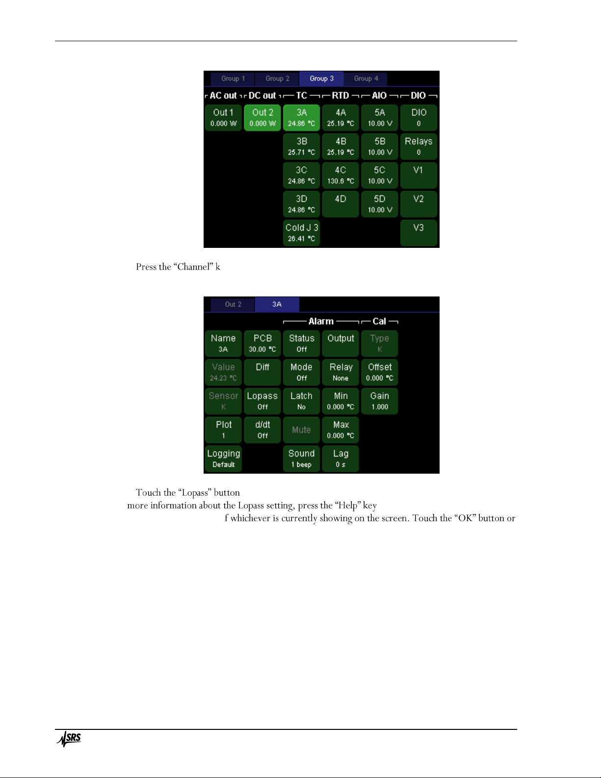
Operation 30
PTC10 Programmable Temperature Controller
ey. At the top of the screen are two tabs, one for each of the two channels
you selected. Touch the tab for the temperature sensor.
to display the list of available lowpass filter time constants. To get
, which displays a pop-up window
with a brief description o
press the Help key again to dismiss the help window.
In the Lopass menu, select one of the six options. Select the largest value that is less than the
response time of your heater. The lowpass filter reduces noise, improving the accuracy of the PID
tuning process and the performance of the tuned PID feedback loop.
Page 47

Operation 31
PTC10 Programmable Temperature Controller
Configure the alarm
To protect your system from runaway feedback (overheating that can occur if, for example, the
PID feedback is configured incorrectly or the se
up an alarm. The alarm automatically shuts off the heater whenever the temperature exceeds limits
that you specify, whenever the sensor becomes disconnected, and whenever the temperature
becomes too high or low for the sensor to measure. On the Setup screen for your temperature
sensor, under the Alarm heading, set the options as follows:
Status: This button indicates if the alarm is currently triggered. It can be used to turn off
latching alarms, but it effect on non-latching alarms.
Mode
Latch
Sound: 1 beep.
Output: select the heater output channel. The selected channel will be forced to zero
overheating your
system if the sensor is disconnected or incorrect feedback parameters are entered.
Relay: For the best possible security, the output should be routed through one of the four
relays (A, B, C, or D) and the Relay button should be set to A, B, C, or D accordingly. The
relay will physically disconnect the heater whenever the alarm is beeping.
Page 48

Operation 32
PTC10 Programmable Temperature Controller
Min: If the PTC10 is controlling a thermoelectric cooler, set the min to the lower
temperature limit of your system. Otherwise, this value should be set well below the lowest
temperature that could normally be produced, so that the min setting can only be exceeded
if something is wrong with the sensor.
Max: Set to the upper temperature limit of your system.
Lag: Set to 1 s. This will prevent small glitches, such as those caused by autoranging, from
triggering the alarm.
Configure the PID feedback loop
The next step is to tell the instrument which temperature sensor to control and the desired
temperature of that sensor.
The PID loop is configured from setup screen of whichever channel you want to use as the heater
output make sure the output that you want to
use is selected.
configuration.
and touch the blue tab for the output channel that you want to
use, Out 2 . You should see the channel setup screen for channel Out 2:
Page 49

Operation 33
PTC10 Programmable Temperature Controller
Select which temperature sensor you want to control: in the umn, touch the
window showing all available input channels appears. Touch the button for the
temperature that you want to control . Sensor 3A is now the PID input for
heater Out 2.
Next, touch the value that you want the temperature to be
driven to
Configure the feedback autotuner
The feedback tuner changes the heater output and measures how much the temperature changes
in response. Before this can be done, the PTC10 needs to be told how much the heater output
should be changed and indicate how long it should wait for the temperature to change.
Go to the Channel setup screen for the hea
damage your system? Change these values if necessary.
feedback, which makes the feedback faster but can also add noise. If D is set to zero, the tuner uses
Page 50

Operation 34
PTC10 Programmable Temperature Controller
a different tuning algorithm that leaves derivative feedback disabled. This is sometimes necessary to
reduce noise in the feedback output.
Start the feedback autotuner
If the system has never been tuned, start with the feedback turned off and the heater at ambient
temperature.
temperature to stabilize at the setpoint. In either case, the key to successful autotuning is to start
with a stable temperature.
If starting at ambient temperature, ensure that the feedback is turned off before enabling the
the tab for the output
If the outputs are disabled, enable t
Output Enable LED turns on and the PTC10 beeps (if pressed again, the Output Enable key
immediately turns all the PTC10 ts off; inputs are not affected).
to start the autotuner. A status window appears and is
updated every few seconds.
Before it begins the actual tuning process, the PTC10 verifies that the Step Y and Lag settings
actually change the temperature by a significant amount, and cancels tuning i The
figure below shows how this is done.
During the first stage of autotuning, the PTC10 compares how much the
temperature changes before vs. after turning the heater on. Autotuning is
ter the heater is
turned on.
The PTC10 first locks the heater output at its current value for one-third of the Lag time and
measures how much the temperature changes. This measurement is the noise and drift. It then
increases the heater output by Step Y and waits for the Lag time to elapse. If the temperature
heater output is returned to its original value, and no changes are made to the feedback gains. If the
Tuning was cancelled because the
response was less than 10 times the noise and drift one or more
of the following:
Page 51

Operation 35
PTC10 Programmable Temperature Controller
significantly increase the temperature, in which
case Step Y should be increased;
increased; or
The temperature was drifting up or down as the test began, in which case the heater should
be left to stabilize at room temperature before trying to tune again.
PTC10 during tuning; tuning will
continue unless you turn tuning off or disable the outputs with the Outpu
good idea to display a graph of heater output and temperature while autotuning (select the two
button in the bottom-right corner.
When tuning is finished, the PTC10 beeps and the PID feedback is automatically enabled. If the
temperature is still below the setpoint, the PTC10 starts increasing power to the heater. The
temperature may overshoot the setpoint, but should eventually stabilize at the setpoint.
The feedback should be re-tuned when:
The temperature units are changed (e.g. from °C to °F)
The output units are changed (e.g. from W to A)
The lowpass filter setting is changed
Page 52

Operation 36
PTC10 Programmable Temperature Controller
Input filters
The PTC10 offers several numeric filters for processing sensor readings. Except for the sensor
calibration, the filters are disabled by default and can be enabled by the user. In the order in which
they are applied, the filters are:
1. Sensor calibration (converts sensor reading in ohms, volts, etc. to temperature)
2. Follow filter (virtual channels only; makes the channel equal to another channel. Not the
same as the PID follow mode.)
3. Offset/gain (multiplies a channel by a gain and adds an offset)
4. Difference (subtracts the value of another channel)
5. Lowpass (filters out noise)
6. Derivative (takes the derivative of the signal with respect to time)
The filters can interact with each other. For example:
If the settings of filters 1 4 are changed and the lowpass filter is enabled, the effect of the
new setting on the sensor reading is lowpass filtered.
Changing the gain may have unpredictable results if the difference filter is enabled, and
changing the offset has no effect if the derivative filter is enabled.
Custom calibration tables have no effect if the follow filter is enabled.
Custom calibration tables
-in sensor calibration curves are appropriate for your sensors, a
custom calibration table can be used to convert the raw sensor reading in ohms, volts, etc. to a
temperature. Each channel can have its own custom calibration table.
Custom calibration tables can be loaded with a remote command or with a USB memory stick.
Format of custom calibration tables
bration table for a 100 platinum RTD that at 0°C has a resistance of 100 ohms:
units = °C
0, 100.00
10, 103.90
20, 107.79
30, 111.67
40, 115.54
50, 119.40
60, 123.24
70, 127.08
80, 130.90
90, 134.71
100, 138.51
Units: units that this table
converts readings to. If omitted, assumed to be Kelvins. The units can be any string of 4 or
fewer characters but must not contain any spaces, periods, plus or minus signs, or numbers. To
Page 53

Operation 37
PTC10 Programmable Temperature Controller
type the degree sig
number pad.
If the sensor readings will be converted to the units specified
by the System.Display.Units setting. If any other units are specified, System.Display.Units is
All other text before the first numeric value is ignored.
Calibration data: The data contains pairs of numeric values: the value to be displayed on the
front panel, followed by the value For example, the
sample table above tells the PTC10 to display 0 °C when the sensor resistance is 100 ohms.
The numeric values may be separated from each other with one or more commas, spaces, tabs,
and/or newlines. to put each calibration point on a separate line as in the
example.
The first value in each pair must be expressed in the units declared at the beginning of the
calibration table, or in Kelvins if no units are declared.
The second value must be in ohms for resistive sensors, volts for diode sensors and analog I/O
channels, or millivolts for thermocouples. For heater driver channels, the native units are by default
watts, but can be changed to percent, volts, or amps with the
If in doubt, look at which units the reading is displayed in when System.Display.is set to
A calibration table must contain at least two calibration points, and the entire file cannot contain
more than 16384 characters (about 400 800 calibration points). Commas should not be used
within numeric values.
The data points do t have to be equally spaced; they can be closely spaced in critical
temperature areas and more widely spaced in outlying areas. For RTDs, the interval between data
points should be 10°C or less to ensure the best possible (0.1 mK) interpolation accuracy. For
thermistors, an interval of 1°C or less should be used.
The displayed value must constantly increase or decrease throughout the entire file, and there
. Likewise, the measured value also has to increase or decrease
monotonically. However, the displayed and measured values can go in opposite directions.
The calibration data must cover at least the entire expected range of measurements, which in the
example above is 0 to 100°C. When readings fall outside the range of the calibration file, no data
appears on the display, and any PID feedback loops that use the affected channel are frozen.
Furthermore, while the PTC10 normally uses a cubic spline algorithm to interpolate between the
calibration points, between the first and last two points a less accurate linear interpolation
algorithm is used. So the calibration table should ideally extend at least one point beyond the range
that you expect to use.
The order of the data points can be reversed (measured value first, displayed value second) by
adding a tilde to the beginning of the file. The tilde must be the first character in the file, appearing
before the units declaration and any other header information.
How to load custom calibration tables
USB memory stick: create a text file containing the calibration information as described
above. The name of the file should be the name of the channel plus the extension
directory -level directory of a USB storage device, and copy the .txt file
into the directory. Plug the storage device into the PTC10, and the PTC10 automatically loads the
files. The device can then be removed.
Remote command: send the command:
Customcal <channel> <calibration data>
Page 54

Operation 38
PTC10 Programmable Temperature Controller
where <channel> is a channel name and <calibration data> is the calibration information as
described below. The data must be on a single line and the entire command must not contain more
than 4092 characters.
How to verify that a custom calibration table is loaded
If a channel uses a custom calibration, th name appears in bold on the Select screen.
For more details, go to the Channel Setup screen and press the Channel.Cal.Details button to see
, a
description of the problem.
file has any values after the header with no numeric characters, if the values are not monotonically
increasing or decreasing, or if the file ends with a temperature value.
Once a custom calibration table is loaded, it remains in effect until one of the following occurs:
A different calibration table is applied to the same channel, using either a USB memory stick
or remote command.
The calibration type (set with the Channel.Cal.Type button
The following have no effect on custom calibration tables:
Unplugging the USB device with the calibration tables.
Plugging in a USB device that does not contain a calibration file for the channel.
Restarting the PTC10.
Virtual channels
The PTC10 has three virtual channels named V1, V2, and V3. You can set these channels to any
value or make their value follow the value of another channel. The value can then be graphed or
saved to the log like any other channel. Here are some uses of virtual channels:
Show the rate of change o
You could just do this in the original channel, but using a virtual
channel lets you display both the original data and the rate of change side-by-side.
Show the d
virtual channel lets you keep the original data.
Run this macro to continuously set the value of a virtual channel to a feedback setpoint:
[waitForSample V1=#Out1.PID.actual]-1
Now the setpoint can be plotted on-screen and logged to USB.
Run this macro to show the value of channel 3A divided by the value of channel 3B:
[waitForSample #a=#3A #a/=#3B V1=#a]-1
Page 55

Operation 39
PTC10 Programmable Temperature Controller
Logging data to internal memory
The most recent one million readings from each channel are saved in internal RAM and can be
plotted on-screen or retrieved using the getLog instruction. The amount of time that the internal
Log
interval
Time span of
internal log
0.1 second
1.2 days
0.3 second
3.6 days
1 second
12.1 days
3 seconds
36.4 days
10 seconds
121 days
30 seconds
1 year
1 minute
2 years
3 minutes
6 years
10 minutes
20 years
30 minutes
60 years
1 hour
120 years
All saved readings are erased when the log interval is changed.
Data from a single sensor can be logged at two different intervals by configuring one of the
virtual channels (V1, V2, or V3) to follow an existing channel (set the IO type of the virtual
channel to Input, then touch the Follow button) and then setting its log interval to a different value.
Logging data to USB
The PTC10 can record channel readings on removable USB memory devices such as USB hard
drives or flash memory keys. When a USB device is plugged in, it takes the PTC10 several seconds
(normally about 5 seconds) to recognize the device and for the USB logging feature to become
available.
A small dark-red circle in the upper-right corner of the screen appears when a USB device is
present but USB logging is turned off. The circle turns light red whenever data is being logged to
USB. If no USB stick is present, the circle disappears completely. To log data to a USB device, plug
the device into the PTC, touch the dark-red circle, and wait a few seconds until it turns light red.
Touch the circle again to stop logging.
The PTC10 cannot read logged data from the USB memory. Data shown on the plot screen
always comes from RAM.
Do not unplug a USB device or switch the PTC10 off while the PTC10 is logging to the device.
Either of these actions causes
off, touch the USB logging indicator in the upper-right corner of the screen and wait for it to turn
dark.
ADC sampling and logged data
The PTC10 has two different sampling rate settings: one controls how often data is acquired, and
another con
Page 56

Operation 40
PTC10 Programmable Temperature Controller
A/D rate
The A/D (analog-to-digital conversion) rate controls how often a data point is acquired from
each channel. All channels are read at the same A/D interval, which by default is 300 ms. This
setting mainly affects the performance of feedback loops: the faster the A/D rate is, the more
quickly the PID loops can respond to changing temperatures; the slower the A/D rate, the less
noise there is in the PID output.
By default, the A/D conversion process is synchronized with the AC line voltage and the A/D
rate can only be set to multiples of the AC line period. For example, if the A/D rate is set to 100
ms, A/D conversions occur every six cycles of the AC voltage if the PTC10 is plugged into a 60 Hz
AC wall socket, or every five cycles for 50 Hz AC. This prevents 60 Hz noise from aliasing into
temperature readings, which would cause a slow sinusoidal variation in the readings. 60 Hz noise
still creates a constant offset in temperature readings, but the offset is usually too small to be of
concern with thermocouple readings and can be removed from RTD readings using current
reversal.
jumper on the motherboard s
possible to set the A/D rate to any value between 10 and 1000 ms with a resolution of 1 µs (note
that the jumper should only be moved while the system is switched off). However, the A/D
conversions will no longer be perfectly synchronized to the AC line voltage, even if the A/D rate is
set to a multiple of the line period. As a result, low-frequency sinusoidal interference may appear in
your temperature sensor readings. The frequency of the noise is the difference between the AC line
frequency and the closest multiple of the ADC conversion rate in Hertz. For example, if the A/D
conversion rate is 10 Hz and the AC line frequency is 60.1 Hz, a sine wave with a frequency of 60.1
(6·10) = 0.1 Hz may be superimposed on all temperature readings.
This interference can be minimized by setting the A/D rate to either 90 Hz (if the line frequency
is 60 Hz) or 75 Hz (for a 50 Hz line frequency) and then setting the lowpass filter to a value of at
least 3 seconds on all input channels.
Log rate
The log rate controls how often channel readings are logged. The log rate can be set
independently for each channel; the default is a point every 0.3 seconds. Normally the time
between log points should be longer than the time between A/D samples, in which case multiple
A/D readings are averaged together to create each logged value. If, on the other hand, the time
between log points is shorter than the time between A/D samples, each A/D reading is recorded
more than once in the log.
The plot screen always displays logged data. Therefore, a slow log rate reduces the noise visible
in the graphs and may produce a stairstep appearance, while a fast log rate produces graphs with
more detail.
Format of PTC10 log files
The PTC10 are in a .CSV format that s compatible with most spreadsheet programs.
The first line contains a comma-separated list of channel names and each subsequent line contains a
comma-separated list of values. The first value in each line is the time in milliseconds since 2000.
The data readings are sav
changed while logging, there will be a discontinuity in the data.
If a sensor was disconnected, its reading was out of range, or no reading was acquired at the
indicated time, then its value is empty and two consecutive commas appear.
Page 57

Operation 41
PTC10 Programmable Temperature Controller
of the I/O cards.
Automatic fan control
At every A/D conversion, each I/O card reads internal temperature sensors and determines how
fast it needs the system fan to run. The main system processor reads the desired fan speed from
each I/O card and, if the System.Other.Fan contr , sets the fan to the fastest
requested speed.
For the PTC430 DC output card and PTC440 TEC driver, the requested fan speed depends on
the temperature of the amount of current being delivered, the voltage range,
and the voltage drop across the heater.
For the PTC320 thermistor/diode/RTD reader, PTC321 RTD reader, and PTC330
thermocouple
temperature specified with the Channel.PCB control. If the card temperature is below its
Channel.PCB setting, the card
Since the default PCB setting is 30°C, the temperature is normally regulated only if the PTC10 gets
unusually warm.
To improve the thermal stability of the input cards, the Channel.PCB setting of one card can be
reduced to a value just below its normal temperature, such that the fan is always running and the
kept at the Channel.PCB value. However, if the PTC10 outputs
a large heater current, the fan speed increases to keep the output card cool and the temperature of
the input cards may fall out of regulation.
Manual fan control
he fan speed can be manually set by
changing the System.Other.Fan control to a value other than auto. In this case, the fan speed
requested by the I/O cards is ignored. If the fan is turned off completely, the user must ensure that
the temperature inside the PTC10 does not exceed 35°C or damage to the PTC10 may occur. In
addition, temperature inputs may not be accurate at elevated temperatures.
The PTC430 DC output card and PTC440 TEC driver are prone to overheating if the fan speed
is manually set to a value that is too low, especially if the card is operated at a high voltage range
and heater resistance is low. If the PCB temperature of one of these cards exceeds 60°C, its output
is automatically shut off. Set the output to zero to re-enable it, for example, by pressing the Output
Enable key (which will disable all
Besides the main system fan, the PTC10 also has an internal fan that periodically turns on to keep
the main power supply cool. This fan is unaffected by any user-accessible setting.
Page 58

Operation 42
PTC10 Programmable Temperature Controller
To control a temperature, the PTC10 must be connected to a temperature sensor that measures
the temperature in question, and to a heater or cooler that raises or lowers the temperature when
power is applied. Although the heater/cooler will just be cal
following principles apply whether it is a resistive heater, a thermoelectric device that can both heat
and cool, or a cooling-only device such as a fan.
How sta
Under ideal conditions, when equipped with a PTC320, 321, or 323 input card, the PTC10 can
regulate temperatures to within 1 mK. In practice, though, the level of stability mainly depends on
external factors such as the amount of ambient temperature variation, the size of the sample
being heated, and the type of sensor and heater used. To achieve optimum stability:
An appropriate thermistor, RTD, or diode for your temperature range must be used. Divide
the noise specification of the PTC10 input card (shown in the front of this manual) by the
estimate the
best-case stability for that sensor.
The sample should be small compared to the heater, and the sample and heater should be in
good thermal contact.
The system must be able to cool down as fast as it can be heated up. Cooling rates can be
very slow if the setpoint is close to the ambient temperature or the sample is thermally
insulated. Under these conditions, thermoelectric devices generally produce more stable
temperatures than resistive heaters since they can actively cool the sample.
If the PTC10 is controlling the temperature of an environmental chamber, the response time
can be improved (at the expense of added vibration) by using a flow-through configuration in
which moving air is heated or cooled before it enters the chamber.
Ambient temperature variations must be minimized. It may be necessary to enclose the
temperature-
Basic PID feedback concepts
The PTC10 supplies a varying current, voltage, or power to the heater, and assumes that the
measured temperature will increase or decrease in a roughly linear fashion with this output signal.
on external factors that vary unpredictably such as, for example, the ambient room temperature.
Therefore, to maintain a consistent temperature, the heater power has to be determined by an
algorithm that can monitor the temperature (T) and continually adjust its heater output (Y) with
the amount of heater output required to maintain that temperature.
In the PTC10, as in most other temperature controllers, the algorithm used is PID feedback, which
is actually a combination of three algorithms.
The proportional feedback algorithm determines the error, i.e. the difference between the
desired temperature (the setpoint) and the actual temperature T. The output Yp of the proportional
feedback algorithm is just the error multiplied by a constant, P:
E(t) = (setpoint T(t))
Page 59

Operation 43
PTC10 Programmable Temperature Controller
Yp(t) = P · E(t)
As the actual temperature approaches the setpoint, the proportional output Yp decreases to zero, at
which point no power is supplied to the heater.
Normally, however, some power is required to keep the heater at the setpoint, which is why the
integral feedback algorithm is needed. It multiplies the error by a constant (I) and adds the result
to the previous integral output:
Yi(t) = I · E(t) + Yi(t 1)
As the actual temperature approaches the setpoint, the rate of change of the integral output Yi
drops to zero. In effect, integral feedback sets the steady-state heater power.
Derivative feedback tries to predict what the temperature will be in the future by multiplying
the rate of temperature change by a constant, D:
Yd(t) = D * (T(t 1) T(t))
If the temperature is increasing (and D is positive), derivative feedback reduces power to the
heater; if the temperature is decreasing, derivative feedback increases power to the heater.
The output of the PID feedback loop (i.e., the heater power) is the sum of the three feedback
algorithms:
Heater power = Yp(t) + Yi(t) + Yd(t)
The key challenge to using a PID feedback loop is determining the best feedback gains. The
constants P, I, and D are different for every apparatus and must be determined experimentally. As a
variations; if they are too high, the feedback responds too much and overshoots the setpoint, and
both heater power and temperature may begin to oscillate. The faster the temperature changes in
response to the heater, the larger the gains can be.
Manual tuning
In this section we will use step response curves to illustrate some basic aspects of how the three
feedback parameters P, I, and D affect feedback performance.
Proportional: the figure below illustrates the effect of changing the proportional gain P. The
top graph shows the power being delivered to a heater by a PID feedback loop during four separate
tests, while the bottom graph shows the temperature of the heater during the same tests. Each test
is identical except for the value of P. At 1 minute, the setpoint is increased from 60 to 70°C. When
P = 1 W/°C (second curve from top), the feedback loop exhibits a perfect response; that is, the
temperature rapidly increases to 70°C with a slight overshoot that serves to minimize the settling
time. If P is increased to 2 W/°C, the temperature responds more quickly but then overshoots the
setpoint by an excessive amount, causing the system to oscillate.
Page 60
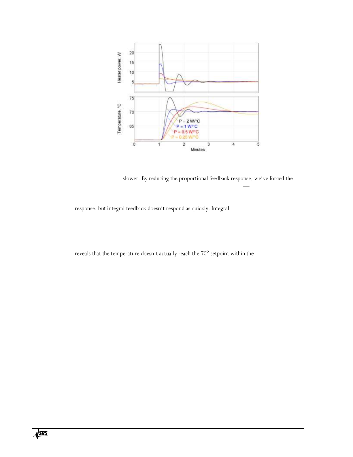
Operation 44
PTC10 Programmable Temperature Controller
Interestingly, decreasing the proportional gain to 0.5 or 0.25 W/°C also results in more
overshoot and can even cause oscillations, despite the fact that the heater response is smaller and
the temperature rise
integral feedback to take more responsibility for raising the heater power and as the next figure
illustrates, the integral feedback has a greater tendency to overshoot and oscillate.
Integral: as with proportional gain, increasing the integral gain I also results in a larger heater
feedback is slow because it
works by adjusting its previous output, rather than re-calculating its output from scratch at each
feedback cycle. Therefore, integral feedback has a tendency to overshoot the setpoint and cause
oscillations.
When I is reduced to 0.001 W/°C/s, the temperature at first responds quickly due to the action
of the proportional feedback. However, close inspection (see the lowest trace in the bottom graph)
time period shown.
Without enough integral gain, temperature errors tend to persist. As an approximate guide, the
integral gain should be about one-tenth the proportional gain.
Page 61
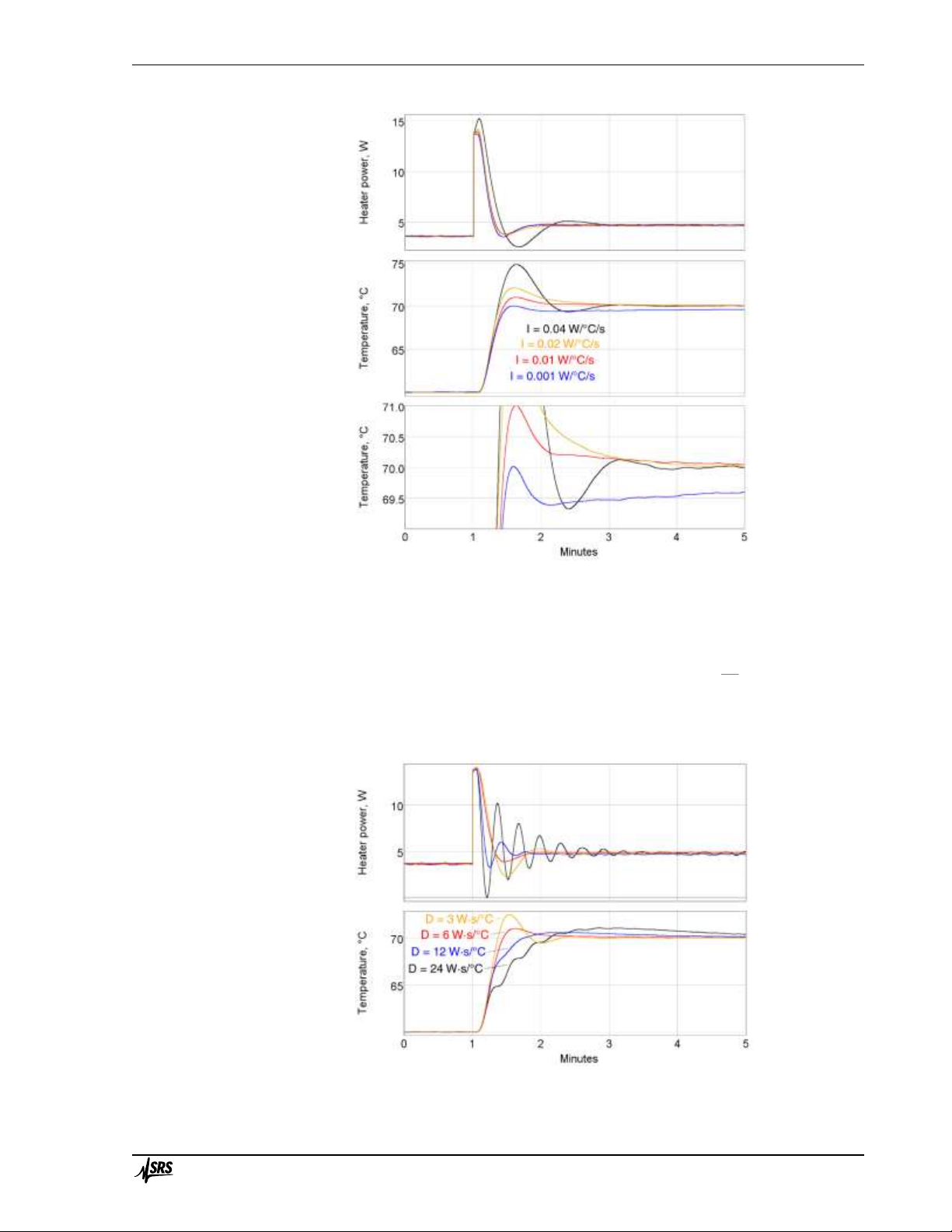
Operation 45
PTC10 Programmable Temperature Controller
Derivative: derivative feedback reduces the heater output whenever the temperature is rising
rapidly. In the example below, when the derivative gain D is increased from 3 to 6 W·s/°C, the
amount of overshoot and oscillation decreases. The temperature rise is also a little slower, but
because there is less oscillation the system stabilizes at 70°C sooner.
However, if the derivative gain is too large, it too can produce oscillations because when the
temperature is rising rapidly, derivative feedback reduces the heater output, which causes the
temperature to rise more slowly, which makes the derivative feedback increase the heater output,
and so on.
Page 62

Operation 46
PTC10 Programmable Temperature Controller
With the right amount of derivative feedback, we can increase P and I to levels that would
otherwise cause oscillations, and thereby obtain faster, more responsive feedback control.
Automatic tuning algorithms
During automatic tuning, the PTC10 changes the heater power, measures how much and how
quickly the temperature changes in response, and then estimates the optimum values of the gain
factors P, I, and D. Two tuning algorithms are available on the PTC10: the relay tuner and the step
response tuner.
Relay tuner
Heater power (top) and sensor temperature (bottom) during relay
autotuning. Step Y is 1 W, Lag is 30 s, feedback is initially on, and the
system starts with the temperature stabilized at the 50°setpoint. After the
tuning has finished, the feedback turns on and re-stabilizes the system at
50°C after a few cycles of oscillation.
The relay tuner creates a temperature oscillation by switching the heater between two output
values:
Output
high
= OutputI + (Step Y)/2
Output
low
= OutputI (Step Y)/2
where OutputI
that the relay tuner cannot be started unless the output is greater than (Step Y)/2. For best results,
the output should be greater than Step Y.
The relay tuner begins by disabling the feedback (if the feedback was on) and measuring the drift
and noise of the feedback input signal in the absence of any changes to the feedback output. The
drift-and-noise measurement continues for one-third the amount of time specified with
control; the resulting drift-and-noise value is the difference between the largest and smallest input
signal observed during this time.
After the drift and noise measurement, the relay tuner sets the heater output to Output
low
for the
Lag time to start the oscillation. If during this period the feedback input does not change by at least
ten times the drift-and-noise value, an error message is displayed in the Status window and tuning is
Page 63

Operation 47
PTC10 Programmable Temperature Controller
cancelled. If this occurs, either 1) ensure that the temperature is stable before starting the step
respond, increase the Lag time.
The tuner then sets the output to the Output
high
value. Then, each time the temperature crosses
its initial value (50 °C in the figure above), the output is switched from high to low or low to high.
This produces a temperature oscillation 180° out of phase with the output oscillation. The tuner
performs two oscillation cycles, not including the kick start, and measures the period and
amplitude of the second oscillation.
The relay tuner has to wait several times for the temperature to cross its initial value. If the
temperature measurement is disturbed during this time (for example, if the temperature sensor is
moved, or if the sensor is in an oven and the oven door is opened), the temperature may never
cross its initial value and the tuner may run indefinitely without finishing.
Step response tuner
Heater power (top) and sensor temperature (bottom) during step response
autotuning. Step Y is 2.5 W, Lag is 45 s, feedback is initially off, and the
system starts at room temperature. After the step response is complete,
the feedback turns on and the temperature drops before stabilizing at the
50°C setpoint.
The step response tuner makes a single change to the amount of power delivered to the heater,
and measures how much and how quickly the temperature changes in response.
The step response tuner begins by disabling the feedback (if the feedback was on), and measuring
the drift and noise of the feedback input in the absence of any changes to the output. The drift-andnoise measurement takes one- and-noise value is the difference between the largest and smallest input signal during this time.
period the feedback input does not change by at least ten times the drift-and-noise value, an error
that the temperature is stable before starting the step response; or 2) increase step Y; or 3) if it
The tuner continuously measures how quickly the feedback input changes, (i.e., the slope of the
feedback input with respect to time). Tuning ends once the lag period has passed and the most
Page 64

Operation 48
PTC10 Programmable Temperature Controller
recent slope is less than half the largest slope. The tuner then calculates the maximum slope, the lag
time, and the total response, and uses these values to calculate the PID gains.
the feedback input channel to achieve accurate tuning results. Since the relay tuner does not require
sensitive to noise than the step response tuner.
if both its high and low
; otherwise, it selects the step response tuner. For example, if
the out o negative) when autotuning is started, the step response tuner runs
because the relay tuner would require a negative output.
Aggressive, moderate, and conservative tuning
Both the step response and relay tuners offer aggressive, moderate, and conservative tuning
options. Conservative tuning theoretically produces zero overshoot and is usually the best choice
when the temperature needs to follow a changing setpoint. The aggressive tuning option
theoretically produces 25% overshoot (although in fact it tends to be larger) and is usually the best
choice for applications in which the setpoint is constant. Moderate tuning produces a very stable
feedback loop that behaves reasonably in a wide variety of situations.
The figure below compares when we change the setpoint from 60 to 70°C
after relay tuning with the aggressive, moderate, and conservative options. In this case,
conservative tuning produces the best response.
However, the results are much different if we look at how the system responds to a thermal
disturbance. The next figure shows how well the system recovers when we start blowing air over
the heater with a fan. The setpoint is a constant 60°C. In this case, aggressive tuning produces the
best response.
Page 65

Operation 49
PTC10 Programmable Temperature Controller
The actual behavior of your system might vary significantly from the behavior shown in these
figures. In any event, the feedback gains determined by the automatic tuning algorithms should
generally be regarded as only a starting point. In critical applications, the gains normally need to be
manually adjusted to achieve good feedback performance.
Using the automatic tuner
Start with a stable temperature. Before the autotuner is started, the temperature must be
he easiest way to get a stable temperature is to let
the system sit undisturbed for a long period of time with the heater off. On the other hand, if the
PID gains have been set before and just need to be re-optimized, it may be easier to turn the
feedback loop on and let the feedback stabilize the temperature. The autotuner can be started with
the feedback either on or off.
Disable or enable derivative feedback. Because derivative feedback can amplify sensor
noise, it may sometimes be preferable to disable it. If the derivative feedback gain is set to zero
before autotuning begins, derivative feedback is disabled and the autotuner calculates P and I
feedback gains, leaving the derivative feedback set to zero. In contrast, if the derivative feedback
gain is initially nonzero, the autotuner calculates P, I, and D feedback gains using a more aggressive
autotuning produces faster-acting feedback but more noise. If your temperature sensor is noisy or
Set the step size and lag time.
controls how long the PTC10 waits for a response. If either value is too small,
the PTC10 may, after attempting to tune, display a message saying that there was an insufficient
response. If the values are too large, tuning will take longer than necessary and your heater will get
excessively hot.
Start tuning. To begin tuning, go to the channel setup screen and set the tuning mode to
If the tuner finishes successfully, a high-pitched tone plays and the feedback loop starts running. If
the tuner was unsuccessful (because Output Enable was off, the heater was unplugged, the
temperature sensor was unplugged, the heater was out of range, or the response was too small), a
low-pitched tone plays and the feedback loop is turned off.
When PID tuning is start ars.
Page 66

Operation 50
PTC10 Programmable Temperature Controller
window does not cancel autotuning; to cancel autotuning, either 1) ;
2) touch th or 3) disable all out
If the status window is dismissed, it can be displayed
Explanation of error messages produced by the autotuner
One of the following messages appears in the Tuning Status window if tuning was unsuccessful. If
Tuning was cancelled because the response was less than 10 tim es the noise and
drift
This message indicates that the heater produced an insufficient temperature response. It can
result from any of the following factors:
The temperature was not stable before the autotuner was started, or the temperature was
changed by some external factor after the autotuner was started. In particular, after running
-stabilize before running the
autotuner again.
The autotuner disturbance size (Step Y) was not large enough to create a noticeable change
in the temperature.
The autotuner wait time (Lag) was not long enough for the heater to change the
temperature.
To determine the source of the problem, look at a dual plot with the heater output on one plot
and the sensor temperature on the other. Make sure that the temperature was stable before the
heater turned on and that it changed significantly after the heater was turned on.
Autotuning was cancelled because the Tune->Mode control was set to "Off"
This message indicates that the user turned off autotuning (by setting the autotuning mode to
Autotuning was cancelled because the PID mode was set to m anual.
The user turned off PID feedback while the tuner is running. The tuner is unable to run when
PID feedback is turned off.
Autotuning was cancelled because the PID mode was set to \"follow\"
Tuning was cancelled because the input was disconnected
No sensor signal was detected. Ensure that a sensor is plugged in and that its reading is not blank.
If the reading is blank, an incorrect sensor range, sensor type, or calibration may be selected.
Unable to tune feedback because the outputs are disabled. Press the Output Enable
button to enable outputs.
The outputs must be enabled before autotuning, or else the PTC10 will not be able to provide
any power to the heaters.
Page 67

Operation 51
PTC10 Programmable Temperature Controller
Unable to tune feedback because the heater is disconnected
This message appears when the heater is connected to channels Out 1 or Out 2 and the measured
heater resistance is less than 1 ohm or greater than 10,000 ohms.
Unable to tune feedback due to a hardware fault in the heater output
This message appears when the heater is connected to channels Out 1 or Out 2 and the current at
the + and terminals is not equal, or current was detected when the heater was supposed to be
off, or the measured current differs from the expected current. Make sure that the heater is not
shorted to ground or to another power supply.
Unable to tune feedback because the heater is under range
Unable to tune feedback because the heater is over range
If Step tuning is selected, the heater output must be less than the maximum output minus Step Y.
If Relay tuning is selected, the heater output must be less than the maximum output minus Step
Y/, and greater than the minimum output plus Step Y/2.
Suggestions for best tuning results
mperature on
separate graphs. Make sure that you can see the temperature begin to rise or fall after the
heater output changes.
If tuning fails, let the temperature stabilize and try increasing the step Y or lag before
attempting to tune again. You may also need to increase the lowpass filter time constant.
The temperature must be stable when tuning is started. Either the feedback must be running
and stabilized at the setpoint, or the heater must be off and the temperature stabilized at the
ambient temperature.
Set the lowpass filter on the input (temperature) channel to a value just below the expected
response time of the system. The step response tuner in particular requires adequate lowpass
filtering to produce accurate results.
Make sure the syst
process.
Since the ideal feedback parameters usually vary with temperature, run the tuning algorithm
at about the temperature at which the feedback will be used. If the system has never been
tuned before you may need to tune at room temperature, then let the feedback bring the
system to its working temperature, and re-tune at the working temperature.
The autotuning algorithm assumes that the temperature is a linear function of heater power.
y the algorithm may not be
perfectly accurate and may need to be manually adjusted.
Page 68

Operation 52
PTC10 Programmable Temperature Controller
The front panel has six menu keys to the left of the display .
These keys can be pressed at any time to display one of the six main screens. Each of the main
screens except for the Program screen has six columns of buttons, usually with a column name at
the top of each column. Each button has a name in large text and, usually, a value beneath the name
in smaller text.
In this manual, buttons are referred to by the name of the screen (Select, Numeric, Plot, etc.),
the name of the column (if any), and the name of the button, separated by dots. For example,
of the System screen. The
(RS-232, USB, etc.) as a remote command.
-
s
USB logging indicator
If a USB memory stick is plugged into the PTC10, a small dark-red circle appears in the upperright corner of the screen. Touch the circle to turn USB logging on; the circle will turn light red to
indicate that data is being logged to USB. Touch the circle again to turn USB logging off.
Removing the USB memory device or powering down the PTC10 without first ejecting the
device causes loss of data and corruption of the memory device. A corrupted device should be
repaired by plugging it into a PC and running a program such as chkdsk (Windows) or fsck (Linux).
information about whichever window
bring up the Value inpu
with pop-
When the PTC is turned on, all outputs are disabled (however, inputs function normally). This
vide power to
the heaters. To turn on the outputs, press
that were previously running begin to provide power to the heaters.
If the outputs are enabled, pressing
them to zero. Inputs continue to function normally. In an emergency situation, the Output Enable
key is the quickest way to turn off the PT -enabling the outputs immediately returns
all outputs to their previous values.
In certain cases it may be desirable to have the PTC power up with the outputs enabled to ensure
that feedback loops automatically resume after a power failure. This can be accomplished with a
Page 69

Operation 53
PTC10 Programmable Temperature Controller
The Output Enable key is not intended to prevent electric shocks. When handling exposed
heater wires, always disconnect the wires from the PTC10 or unplug the PTC10 from the wall.
Press and hold the "Output Enable" key for 3 seconds to put the PTC10 into standby mode. In
standby mode, the outputs are turned off, data acquisition and macros are paused, the front panel
display and system fan are shut off, and the system does not respond to remote commands. RTD
excitation currents are still on, and an internal cooling fan may switch on occasionally. Press the
"Output Enable" key again to leave standby mode.
Each column of buttons on this screen represents one I/O card, and each button shows the name
and the current value of an I/O channel. The value may not appear if no sensor or heater is
connected to the channel.
The PTC10 includes two I/O cards as standard equipment: a 4-channel, ±10V analog I/O
(AIO) card in slot 5, and a digital I/O (DIO) card in slot 6. These cards appear in the two rightmost columns of the Select screen. The remaining four columns show any optional I/O cards that
have been installed.
Buttons turn red at is, if the alarm is enabled and the reading
is outside of the alarm limits or no sensor is connected. The name of the channel appears in bold if
the channel uses a custom calibration table.
o view on the Numeric, Plot,
and Channel screens. The top of the Select screen has four Group tabs that let you save and recall
button to change the selection group.
Page 70

Operation 54
PTC10 Programmable Temperature Controller
This screen displays the current values of the selected channels as numbers. The more channels
that are selected, the smaller the displays are. If enough space is available, an annunciator may
appear that indicates whether the sensor or heater is disconnec
u outputs are disabled
Input displays turn red whenever the alarm is triggered. The name of the channel appears
in bold if the channel uses a custom calibration table.
Repea Touch one of
the channel displays to show setup menu for the channel.
This screen shows logged data from the selected channels on one or more graphs. Press the Plot
key repeatedly to cycle between the four formats described below (single, multi, custom, and
ponytail).
The Plot screen always shows logged data. If, for example, the log interval is set to 10 s, the
graph will have a very 10 seconds.
Page 71

Operation 55
PTC10 Programmable Temperature Controller
Touch the tabs at the top of the screen to change the selection group. Each of the four groups
remembers its graph format (single, multi, etc.), X range, and Y range. Therefore, when you
change the selec so change.
Single plot
Up to eight selected channels are shown together on one graph with a single Y axis. If more than
eight channels are selected, only the first eight are shown.
Single plot mode showing the ambient temperature measured by two
thermocouples (channels 3B and 3C) and one Pt100 RTD (4B). RTDs
have a much lower noise level than thermocouples.
Multi plot
Each channel is shown in its own graph with an independent Y axis. If more than eight channels
are selected, only the first eight are shown.
In multi plot mode, each sensor gets its own graph. The X scale is the
same for all 3 graphs, but the Y scale is different.
Page 72

Operation 56
PTC10 Programmable Temperature Controller
Custom plot
Each channel is assigned to a plot according to its Channel.Plot setting.
In custom plot mode, the user can manually assign each channel to a
graph. Here the thermocouple inputs have been assigned to plot 1 and the
RTD input to plot 2.
Ponytail plot
Like Single plot, up to eight selected channels are shown together on one graph. Each trace is
offset by its initial value so that the trace begins at zero. The offset is recalculated whenever you
touch the graph to zoom or pan, or whenever you switch to another screen and back to the Plot
screen. If , the offset is never recalculated.
Using the ponytail plot does not affect how channel values are logged; the offsets are only applied
to the plots, not to the log files.
In ponytail plot mode, all traces are offset so that they start at zero.
Page 73

Operation 57
PTC10 Programmable Temperature Controller
Zooming and panning
To change the X axis scale of a plot, touch anywhere inside the plot:
Touch the right half of the plot to zoom in
Touch the left half to zoom out
Drag to pan.
Whenever the most recent data is visible on the graph, the graph automatically scrolls to keep the
most recent data
bottom-left corner of the screen to indicate that scrolling is disabled. To show current data and
Graphs that appear together on a screen always have the same X axis range. However, each
selection group has its own, independent X axis range.
How to change the X axis scale
How to pan the graph horizontally
Page 74

Operation 58
PTC10 Programmable Temperature Controller
By default, the PTC10 continually adjusts the Y-axis scale to accommodate all the data on the
graph. Each graph has its own, independent Y axis scale. To change the Y axis scale for a particular
graph, touch the area to the left of its Y axis.
Touch the top third of the Y axis to zoom out. Automatic scaling is disabled, so the Y axis
scale no longer changes as new data is acquired.
Touch the middle third to 1) re-enable automatic scaling and 2) reset automatic scaling, that
is, ignore previously-acquired data and adjust the Y range to accommodate only new data.
Touch the bottom third to zoom in. Automatic scaling is disabled.
Drag to pan.
How to change the Y scale of the bottom graph
How to pan the bottom graph vertically
Page 75

Operation 59
PTC10 Programmable Temperature Controller
Program
A program is a set of one or more instructions that can be used to customize the behavior of the
instrument. Programs can be input over the RS-232, GPIB, USB, or Ethernet interface, from the
program screen, or as a files on a USB memory device. Regardless of how a program was input, its
progress can be monitored from the program screen.
The Program screen has an Input window, which shows text received over RS-232 or GPIB; a
Messages window, which shows responses and error messages from the PTC10; and a Progress
window, which shows the list of instructions that make up the current program.
If a program is not running, you can compose or modify a program by touching a line in the
Progress window. Touching a blank line brings up a list of possible commands. Touching a line that
already contains an instruction brings up a list of three options: you can add a new instruction on
the line above the one that was touched; delete the instruction that was touched; or replace the
instruction that was touched.
The Program screen has six buttons:
Play sym bol
If a program is displayed but not running, press this button to start the program. If a program is
running in the currently-selected tab, the button is highlighted and pressing it stops the program.
Pause symbol
Press this button to temporarily pause the program running in the currently-selected tab. Press
the button again to resume running the program.
Clear
Erases all text from the Input, Messages, and Progress windows. Unless it has previously been
saved, the current program is lost. This button cannot be pressed while a program is running in the
current tab.
Load
Touch this button and a list of programs stored in memory is displayed. Programs can be stored
in memory with the Program.Save
or by attaching a USB device with text file
the list and its component instructions are displayed in the Progress window, replacing whatever
was previously in the window.
Page 76

Operation 60
PTC10 Programmable Temperature Controller
The Program.Load button can be used to edit a previously-saved program: load the program,
then edit it in the Progress window, and finally re-save the program with the Save button.
To call a previously-
use the Program.Load button, since it would erase the rest of the program. Instead, touch the
Progress window and select the saved program from the list of commands. The Program.Load
button cannot be pressed while a program is running in the current tab.
Save
Saves the current program, as shown in the Inpu
a name for the program. Up to 15 programs can be saved. If 15 programs are already saved, the
Save button will have no effect.
hing a line in
any other
instruction) over one of the remote interfaces.
Delete
Touch this button to display a list of programs stored in memory. Select a program from the list
and it will be deleted from memory. The Program.Delete button does not affect the status of
currently-running macros.
Sending programs over RS-232, USB, GPIB, or Ethernet
Programs can be entered from a remote interface such as RS-232, USB, Ethernet, or the optional
GPIB port. Each line of text sent to the PTC10 is run as a separate program (the entire program
must be on a single line). If two or more lines are sent to the PTC10 in quick succession, the
programs may run concurrently; that is, the PTC10 does not finish running the first program
before beginning the second. However, the first program sent will always begin running before the
instruction.
Preparing programs as files on USB memory devices
The PTC10 can also read programs that are stored as text files in a USB memory device. This is
the best way to enter longer programs.
program in a
word processor or text editor
device into the PTC10. To verify that the program is available, look for its name in the Macros
column of the System Setup screen. The program can be run just as if it were saved in the
memory; however, after the USB device is unplugged, the program can no longer be started.
While the PTC10 is running you can unplug the USB device, use a PC to edit a program stored
on the device, plug the USB device back into the PTC10, and run the new version of the program.
button to re-load the program.
Program files can contain up to 16384 characters, and may include multiple lines and comments
(an apostrophe, i.e. a single quote mark, indicates that the rest of the line is a comment). Except
for the first newline after a comment, all whitespace is ignored; each line can be empty or can
contain one or more instructions.
Page 77

Operation 61
PTC10 Programmable Temperature Controller
Preparing programs from the front panel
Simple programs, such as a series of temperature ramps, can be entered from the front panel.
To enter a program f
Progress window. A list of available top-level commands appears.
Any button with a name ending in a dot brings up a sub-menu when pressed. For example, the
commands to change the feedback setpoint or alarm limits for a channel are accessed by first
el
Touch the left square bracket (the button in the upper-left corner). Square brackets surround
Program screen, where the first line in the
Progress window is now a left square bracket.
Touch the Progress window again, anywhere beneath the first line. The list of possible
list of
Page 78

Operation 62
PTC10 Programmable Temperature Controller
the
Touch the OK button. You are returned to the Program screen and the instruction
Page 79

Operation 63
PTC10 Programmable Temperature Controller
e pause instruction has two arguments that
instruction will pause the program for one second.
three times.
Press the start button. While the program is running, the current instruction is highlighted and
the total number of repetitions as well as the number of repetitions remaining appears next to the
appears at the top of the screen. By touching this tab, you can enter and start a second program
while the first program is still running.
Messages window.
Once the program is finished you can press the start button to run the prog
Running concurrent macros
Since a macro can run for a long period of time or even indefinitely,
macro before
macro simultaneously.
The PTC can run at most ten concurrent macros (including the startup macro, macros received
over all I/O ports, and macros started from the Program screen). If an eleventh macro is started, a
message appears and the macro does not run.
If the PTC10 is turned off and turned back on again, macros that were running when the PTC10
was turned off are not restarted.
Page 80

Operation 64
PTC10 Programmable Temperature Controller
screen
The Channel screen includes controls for all settings that affect individual data channels. Sensor
calibration, PID feedback parameters, and alarms are all set up through this screen. Note that the
layout of the screen varies depending on which channel is selected; for example, only output
channels have PID controls, while only input channels have alarm controls.
Only one channel can be set up at a time. One tab appears at the top of the screen for each
channel in the current selection group; select the tab for the channel you want to set up.
Name
Sets the name of the channel. The name must have 10 or fewer characters.
Value
If the channel is an input, this button shows the most recent reading but is grayed out, indicating
not grayed out and pressing this button allows you to enter a new output value. However, if PID
feedback is turned on or Output Enable is off, changing the value will have no effect.
Off
Sets the PID feedback mode to Off, cancels any PID tuning processes currently operating on the
whichever is higher. This
button is only available for output channels.
Low lm t
This control, which is only available for output channels, sets the minimum output. However, if
the minimum is greater than zero, the output is still set to zero whenever outputs are disabled with
should normally be changed when the output units are changed, since the limits are not
automatically converted to the new units.
Hi lm t
This control, which is only available for output channels, sets a maximum limit on the output.
ter. If
the high limit is less than the low limit, the low limit takes precedence.
Page 81

Operation 65
PTC10 Programmable Temperature Controller
Range
If the I/O card has more than one range, pressing this button displays a menu of available ranges.
If the card only has a single range, this button is grayed out.
IO type
Each output channel has an ADC that can measure the actual
-purpose analog and digital I/O channels are bidirectional, i.e. they can be
used to monitor external signals, or to produce signals. In these cases, the IO type button has three
ts a voltage and the value you see on-screen is the
value you a external voltage, and the channel will measure that voltage.
Plot
Indicates which plot the channel will appear in when the Plot screen is showing, the plot type is
Choose one of eight plots for the channel to appear in, where plot 1 is the uppermost plot. If no
Plot screen. For example, if all
selected channels are assigned to plot 4, only one plot appears on the Custom plot screen.
Logging
By default, each chann once every second. This global log rate can
be changed on the System screen (System.Log.Interval). The Logging button makes it possible to
override the global log rate for individual channels.
Figures
Sets the maximum number of digits that are shown after the decimal point for all channel values.
Fewer digits may be shown if the value wouldn fit into the available space. This setting
does not affect logged data, PID feedback, or plots.
If th
the System screen.
Cycle (AC output card only)
The PTC420 has a solid-state relay that can either deliver full power or no power to the heater.
To more precisely control the power delivered to the heater, power is switched on for some
fraction of a preset cycle time, then switched off for the remainder of the cycle. For example, if the
cycle time is 10 seconds, the relay might switch on at time t = 0 s, off at t = 1 s, on at 10 s, off at
11 s, on at 20 s, and so on. This would produce 10% of the maximum output.
The Cycle instruction sets the on/off cycle time. Shortening the cycle period will reduce
temperature swings associated with switching the current on and off, but will also reduce the
lifetime of the relay. The cycle time must be between 1 and 240 seconds inclusive.
Dither (DC output card only)
The DC output card has a 16 bit DAC. For greater resolution, the least significant bit can be
dithered. Dithering is enabled by default.
Page 82

Operation 66
PTC10 Programmable Temperature Controller
Current (4-channel RTD reader and 1-channel thermistor/diode/RTD reader only)
Controls the direction of the sensor excitation current. Reverse the current to detect offsets due
to parasitic thermocouple EMFs or 60 Hz noise. In AC mode, these offsets are automatically
removed by reversing the current at each ADC reading; each reported temperature is based on the
average of the last two ADC readings (cutting measurement bandwidth in half). The PTC320
thermistor excitation current can be turned off entirely with this control.
Current (TEC driver card only)
Controls the amount of excitation current (1 mA, 100 µA, 10 µA, or auto) provided to the
temperature sensor. The sensor excitation current on the TEC driver card cannot be reversed.
PTC440 TEC driver when a resistive sensor is in use. The sensor resistance is continuously
monitored and the excitation current is adjusted whenever the sensor resistance rises above or
drops below the levels shown in the table. T always produces 1 mA when
an LM335 or AD590 sensor is in use.
Sensor
resistance
Excitation
current
<2 k
1 mA
1 20 k
100 µA
>10 k
10 µA
TEC driver (for resistive sensors only)
The overlap of the resistance ranges keeps the PTC440 from rapidly switching back and forth
between two excitation currents. If, for example, the sensor resistance is between 1 and 2 k , the
PTC440 can select either 1 mA or 100 µA excitation, and if possible, it keeps the excitation at its
previous value.
Slew (Only appears on the Out channel of TEC driver cards)
Sets the maximum positive and negative rate of change of the TEC driver output. The rate must
be between 0 and 1000 amps per second, and the default value is 100 amps per second (which
corresponds to an unlimited slew rate at 10 samples/second). Each time the TEC current is set
(either by a PID feedback loop or with the Channel.value control), it ramps to the new value at this
slew rate.
Rapid changes in the TEC current can create electromagnetic interference (EMI) in the
temperature sensor and any other sensors near the TEC. The resulting spikes in the temperature
reading can cause feedback oscillations or noisy temperature readings.
For the slew rate setting to be effective, the A/D rate (set with the System.Other.A/D rate
control) should less than or equal to 100 ms. The slew rate is implemented with a software
algorithm that runs at each A/D conversion, and the TEC driver output has a 13 Hz lowpass filter.
If the A/D rate is set (for example) to 1000 ms, the algorithm only changes the TEC output current
once each second and the output current therefore changes in discrete steps, each of which may
exceed the desired slew rate.
remote command, the TEC output turns off immediately, regardless of the slew rate setting. When
outputs are re-enabled, the TEC output ramps up to its previous value at the desired slew rate.
Page 83

Operation 67
PTC10 Programmable Temperature Controller
Vm ax (Only appears on the Vmon channel of TEC driver cards)
Sets the maximum voltage that the PTC440 TEC driver can output. This control is intended to
protect thermoelectric coolers from damaging voltages. If the measured voltage across the TEC is
above Vmax for more than one second, current to the TEC is automatically shut off. The first time
-panel
display. To turn the current back on again, set the output to zero (for example, by
el menu, or by disabling and re-enabling all outputs with
the Output Enable button).
If the output current suddenly increases and the slew rate setting is too high, it is still possible to
damage the TEC even if Vmax is set to an appropriate value. To prevent such damage, the output
voltage should, if possible, also be limited by setting the output range to the lowest possible value
(e.g., 3V 5A, 6V 5A, or 9V 5A) controls for the output
channel to current values that do not produce excessive voltages.
The TEC voltage can also be limited using
Channel.Alarm.Mode control level Channel.Alarm.Latch control , and the min
and max to the desired voltage limits. Touch the Channel.Alarm.Output button and select the TEC
output channel. The Channel.Alarm.Lag control can be set to 1 s to prevent noise spikes from
inadvertently triggering the alarm, or left at 0 s to better protect the TEC from rapid voltage
increases.
PCB (RTD, thermistor, and thermocouple readers only)
Sets the maximum printed circuit board (PCB) temperature for all channels on the selected card.
System.Other.Fan is set , the PTC10
temperature. The PCB control only appears for I/O
cards that have internal temperature sensors.
The PCB temperature is always in °C, regardless of the System.Display.Units setting. The
default setting is 30°C.
Thermal drift of the RTD or thermocouple inputs can be reduced by setting the PCB
temperature of one card to a lower value. This value should be a few degrees above room
temperature, (i.e., 25°C). Reducing the maximum PCB temperature results in tighter regulation
articularly of the selected card, at the expense of more fan
noise.
However, if a DC output card is being used the system might sometimes turn up the fan speed to
prevent thermal damage to the output card, causing larger internal temperature variations.
Diff (input channels only)
whichever channel is selected in the tab bar at the top of the Channel menu. To turn the
difference feature off, touch Diff , then touch whatever channel is currently selected. The Diff
button then shows an empty value.
Channels with a difference filter can be used as the input for PID feedback loops, in which case
the feedback maintains a constant temperature differential between two locations, rather than a
constant absolute temperature.
Lopass (input channels only)
If a non-zero value is selected, a 6th-order RC lowpass filter is applied to the selected channel.
The lowpass filter removes noise with a period shorter than the indicated time constant but also
increases the effective response time of a sensor.
The lowpass filter should always be enabled on the temperature inputs of all PID control loops.
This is especially true when using step response PID tuning or when derivative feedback is enabled
Page 84

Operation 68
PTC10 Programmable Temperature Controller
(i.e., the derivative gain is nonzero), since these algorithms calculate the change in temperature
over time and therefore produce poor results if highconstant should be just below the response time of the system. When using an AC output card for
PID control, the filter constant should be longer than the cycle time of the output.
When a sensor is disconnected and then reconnected to a lowpass-filtered channel, the PTC
allows one second for the reading to settle. During this time, no reading appears. The output of the
lowpass fil
reading to gradually settle to its new value.
Units (PTC420 AC output card and PTC430 DC output card only)
By default, the output of these heater driver cards is measured
output) and the output units of the DC output
(heater voltage).
d/dt (input channels only)
with respect to time. Since the derivative is normally somewhat noisy, the lowpass filter should be
enabled when the derivative filter is used.
Follow (virtual input channels only)
This button only appears for virtual channels that are configured as inputs. Once a channel is
continuously follows the value of the selected channel.
Difference, derivative, or other filters may be applied to the virtual channel to modify the value.
(assuming that channel 3A exists). The virtual channel now echoes the value of channel 3A. Next
difference between channels 3A and 3B.
Sensor (input channels only)
Selects the sensor type. The button only appears on input channels that support more than one
sensor type. The list of available sensor types varies with the I/O card.
Changing the sensor type has three effects. First, it changes the calibration curve that the PTC10
uses to convert raw sensor readings into temperature. Second, changing the sensor type may affect
how the PTC hardware acquires data from the sensor. For example, if the sensor type of a PTC320
I/O card is changed from Thermistor to Diode, the PTC acquires voltage instead of resistance
readings.
Finally, changing the sensor type affects which buttons appear in the Channel.Cal column as well
as the list of options that the Channel.Cal.Type button offers. For example, if the sensor type is
, the Channel.Cal.Type button offers a list of standard RTD types, Callendarvan Dusen coefficients appear in the Channel.
(thermistor), the Channel.Cal.Type button offers a list of standard thermistor types, and the
-Hart coefficients appear in the Channel.Cal column.
of thermocouple can be
read, the thermocouple type cannot be changed on this card.
Some resistive cryogenic temperature sensors such as Rhodium-Iron, Germanium, and CarbonGlass are not included in the list of available sensor types because they do not have standard
calibration curves. To use these sensors, set the Sensor type to thermistor, RTD, or ROX and load
Page 85

Operation 69
PTC10 Programmable Temperature Controller
manual for more information on custom calibration tables.
Polarity (relays channel of digital I/O card only)
This setting only applies to the Relays channel on the digital I/O card. Changing the polarity
reverses the state of all four relays.
The Polarity setting ensures that the relays are in an acceptable state when the PTC10 is switched
off. When the Polarity is 0, the relays r
f four individual relay values: relay A
can have a value of 0 or 1, relay B can have a value of 0 or 2, relay C can have a value of 0 or 4, and
relay D can have a value of 0 or 8. When the polarity is changed, the value of each relay stays the
same, but its meaning changes as shown in the table below.
Relay state →
Default
(power off)
Relay value
= 0
(alarm off)
Relay value
= 1, 2, 4, or 8
(alarm on)
Back panel pin →
NC
NO
NC
NO
NC
NO
Polarity = 0
Closed
Open
Closed
Open
Open
Closed
Polarity = 1
Closed
Open
Open
Closed
Closed
Open
what the relays revert to when the PTC10 is switched off. If no alarms are
configured, they will stay in that state when the PTC10 is turned back on again.
Channel screen: Alarm column
Each input channel has an alarm. If enabled, the alarm is triggered if any of the following
conditions occur:
The input (or its rate of change) exceeds the user-specified minimum and maximum values
The input exceeds the measurement range of the I/O card
The sensor is disconnected (except on analog I/O channels, which cannot detect
disconnected sensors)
When an alarm is triggered, it can do any of the following:
Play a sound
Trigger a relay on the digital I/O card
Shut off an output channel
The alarm can be programmed to remain triggered until it is manually shut off (latching alarm),
or to shut itself off as soon as the input returns to a value within the alarm limits (non-latching
alarm). The alarm can also be programmed to ignore momentary glitches.
To determine which alarms are currently triggered, look at the Select screen. A small white dot
in the upper-
output enough power to damage
your system. The alarm should be configured to disable the heater output when triggered. For
relay associated with the alarm. Wit ossible for the PTC10 to
Page 86

Operation 70
PTC10 Programmable Temperature Controller
feedback is incorrectly set up.
The following controls are available for input channels only:
Status
Indicates if an alarm condition is currently present on this channel. If a latching alarm has been
also be used to artificially turn the alarm on to test the sound, output channel disabling, and GPIB
status reporting.
alarm immediately turns on. If the alarm is non-latching, it turns off in less than a second; if it is
latching, it stays on unt
Mode
Enables or disables the alarm. The following three alarm modes can be selected:
Off: the alarm never sounds.
Level: the alarm sounds whenever the input exceeds the values set with the Min and Max
controls. The alarm also sounds whenever the input is disconnected or the sensor value exceeds the
range of the input.
Rate /s: the alarm sounds whenever the rate of change of the input (in degrees per second)
exceeds the Min or Max values. The alarm also sounds whenever the input is disconnected or the
sensor value exceeds the range of the input.
Latch
I e
control. If set to No, the alarm turns itself off once the input is again within the alarm limits.
Mute
Temporarily silences the alarm sound but does not otherwise affect the alarm. Once this button
is touched, the alarm stays muted until the alarm condition goes away or until the button is touched
again.
Sound
Controls which sound plays when the alarm goes off.
Output
T
zero and temporarily disabling that chann
the output returns to its previous value and the feedback is re-enabled. This feature can be used to
guard against runaway feedback loops or to otherwise protect equipment from damage due to
excessive temperatures. For example, one or more backup temperature sensors can be
programmed to shut off a PID output to prevent damage in case the primary sensor fails.
he channel
to be shut off. If a channel is already selected, touching it again de-selects the channel and no
channel will be shut off when the alarm triggers.
Relay
If a digital I/O card is installed in slot 6, the alarm can switch one of its four relays o
possible to assign more than one alarm to a given relay, in which case the relay will turn on if any
one of the alarms is triggered.
Page 87

Operation 71
PTC10 Programmable Temperature Controller
Min
The lowest permissible value of the input. The alarm is triggered if the input (or the rate of
change of the input) becomes lower than this value.
Max
The highest permissible value of the input. The alarm is triggered if the input (or the rate of
change of the input) exceeds this value.
Lag
Prevents noise or glitches from inadvertently triggering the alarm. The alarm will not be
triggered until the input has continuously exceeded the min or max setting for this number of
seconds. The lag applies when the alarm is being switched and when it is being switched off.
Channel screen: Cal column
This menu is only available for input channels.
Type
The Calibration Type control affects how raw sensor readings are converted to temperature
measurements. This control does not affect how the sensor is read.
or which custom
calibration tables have been loaded. It does not, by default, appear on the four analog I/O channels,
the digital I/O channel, the relay channel, and virtual channels.
If the I/O card only supports a single calibration curve, the calibration type is grayed out and
cannot be changed, unless a custom calibration is loaded.
If the selected channel uses a custom calibration table, its calibration type reads
then reverts to the normal list of calibration types supported by the I/O card.
The available calibration types depend on the sensor type.
RTDs: Choose ITS-90 for RTDs with an alpha of 0.00385; US for RTDs with an alpha of
0.00392; or Custom to enter your own Callendar van Dusen calibration coefficients.
Thermocouples: Indicates the thermocouple type (E, J, K, N, or T). Cannot be changed, since
the thermocouple type is determined by the back-panel connector.
Thermistors: The available calibration types are named according to the resistance of the
thermistor at 25°C. Thermistors from Omega, Measurement Specialties, Inc. (formerly YSI), and
others that conform to the same calibration curve are supported. Note that unlike RTDs and
thermocouples, there are no international standards for thermistors. Therefore, thermistors from
-in
calibrations even though they have the correct resistance at 25°C.
Diodes: Choose from the list of commercial cryogenic diodes. See the description of the
PTC320 I/O card on page 2 for more information on standard diode calibrations.
A (RTD, thermistor, and diode calibrations only)
B (RTD, thermistor, and diode calibrations only)
C (RTD, thermistor, and diode calibrations only)
R0 (RTD calibrations only)
Custom calibration coefficients. These settings let you define custom calibration curves for some
sensor types without making a custom calibration table. The values can only be changed if the
Page 88

Operation 72
PTC10 Programmable Temperature Controller
RTDs: If the sensor is an RTD, A, B, C, and R0 are the constants for the Callendar van Dusen
equation:
Rt = R0(1 + At + Bt² + (t 100)Ct³) below 0°C
Rt = R0 (1 + At + Bt²) above 0°C
where Rt is the measured resistance of the RTD in ohms, R0 is the resistance of the RTD at 0°C,
also in ohms, and t is the temperature in °C.
If a standard RTD calibration is selected (i.e. IEC751 or US), preset values of A, B, and C are
used. The value of R0, however, is not preset and can be modified.
The Callendaris accurate to about 50 mK in the range -200 400°C. In contrast, class A commercial RTDs that
have not been individually calibrated are accurate to 150 mK at 0°C and 950 mK at 400°C.
re calibrating your own sensor and the calibration points are separated by less than 50°C,
easier and more accurate to load the calibration in the form of a calibration table instead
of calculating the Callendar-van Dusen coefficients.
Thermistors: If the sensor is a thermistor and the calibration type is s , the A, B,
and C settings are the Steinhart-Hart coefficients. The temperature T (expressed in K) is calculated
from the thermistor resistance R (in ohms) using the following equation:
T = (A + B·ln(R) + C·ln³(R))-1
If a standard thermistor calibration is selected, the A, B, and C controls show best-fit coefficients
for whichever curve is selected. These figures are approximations only and are not actually used to
calculate the temperature unless the calibration type is changed to
Diodes: If the sensor is a diode and the calibration
settings are a polynomial fit to the diode calibration curve:
T = A BV CV²
where T is the temperature in Kelvins and V is the voltage across the diode in volts. Note that
polynomial fits are only accurate within a limited temperature range.
If a standard diode calibration is selected, the A, B, and C controls show best-fit coefficients for
whichever curve is selected. These figures are approximations only and may not produce the same
results as the standard calibration curve.
A standard diode or bipolar junction transistor can be connected to the PTC320 input card and
used as a low-cost temperature sensor. In this case a custom calibration must be used. If the voltage
across the diode is measured at two known temperatures, the calibration coefficients can be
calculated as follows:
B = (T1 T2) / (V1 V2)
A = T1 + (V1 · B) + 273.15
C = 0
where V1 is the voltage (expressed in volts) at temperature T1 (expressed in °C), and V2 is the
voltage at temperature T2. The resulting calibration is a linear approximation. For greater accuracy,
a custom calibration table should be used instead of the A, B, C coefficients; see page 36.
Page 89

Operation 73
PTC10 Programmable Temperature Controller
Offset
Gain
The offset/gain filter modifies the value of an input channel as follows:
output = (input · gain) + offset
where input is the input to the offset/gain filter, and output is the output of the filter. This filter
can be used as a simple way to adjust sensor calibrations.
The offset/gain filter is appl
before the other input filters (difference, lowpass, and derivative).
Channel screen: PID column
This menu is only available for output channels. In addition, if no Input channel is selected, all of
the other PID buttons are grayed out.
Input
T
one temperature sensor as the input for more than one PID loop.
Mode
Three options are available:
f: PID feedback is inactive. In this mode, t
control.
: PID feedback is enabled and actively controls the heater output, ideally maintaining the
input channel at the setpoint.
: In this mode, the output continuously tracks the input, with a gain and offset (zero
point) applied. Follow mode can be used if, for example, two identical heater outputs are
needed; one heater channel can follow another that has PID feedback turned on. Follow
mode can also be used (typically on the ±10V aux output channels) to provide an analog
representation of a temperature to other electronic hardware.
Setpoint
The temperature at which the PID feedback loop tries to keep the input.
Zero pt (Follow mode only)
In Follow mode, this value is subtracted from the input. Thus, when the input is equal to this
value, the output is zero. In follow mode, the output is determined by the equation:
Output = (Input Zero pt)Gain
Ram p
This button is used to set the ramp rate in degrees per second, controlling how quickly the
PTC10 heats or cools your system.
Whenever the feedback setpoint is changed, the PTC10 gradually adjusts the ramp temperature
ontrol, below), increasing or decreasing it at the ramp rate
until it reaches the new setpoint. The PID feedback loop, in turn, attempts to control the sensor
temperature such that it tracks the ramp temperature. Assuming the feedback is properly tuned and
Page 90

Operation 74
PTC10 Programmable Temperature Controller
that your heater can respond quickly enough, the sensor temperature should rise or fall at the ramp
rate until it reaches the new setpoint.
If Ramp is set to zero, ramping is disabled and the PTC10 heats or cools your system at the
maximum possible rate.
Ram p T
Shows the temperature that the PID feedback is currently trying to maintain. Ramp T is equal to
the setpoint unless 1) the feedback is disabled or 2) a temperature ramp is currently in progress.
If the feedback is disabled, Ramp T follows the sensor temperature. When the feedback is
enabled, Ramp T increases or decreases at the ramp rate until it reaches the setpoint. This ensures
that the temperature of your sample ramps smoothly to the setpoint at the rate specified by the
. To reach the setpoint more quickly, touch the Ramp T button and enter the
setpoint value.
Once it reaches the setpoint, Ramp T will remain exactly equal to the setpoint until the setpoint
is changed. When the setpoint is changed, Ramp T increases or decreases at the ramp rate until it
reaches the new setpoint.
If the feedback is disabled, Ramp T immediately starts to follow the sensor temperature again. It
ramp to the sensor temperature because the feedback is now off.
The Ramp T button can be used to monitor the progress of temperature ramps. The sensor
temperature could also be used for this purpose, but is subject to noise, external disturbances, and
other artifacts that in some cases could make it difficult to determine the intended temperature.
P
Sets the proportional gain factor. The PID equation is:
Outputt = Pet + 0.5IT( (e0 + e1) + (e1 + e
2 t 2
+ e
t 1
) + (e
t 1
+ et) ) + (D/T)(et e
t 1
)
where P, I, and D are the derivative gains, et is the error (the difference between the setpoint and
the PID input signal) at time t, and T is the ADC sampling time. Thus, larger values of P, I, or D
produce a faster feedback response. Increasing P or I tends to create oscillations, while increasing D
reduces oscillations but adds noise. Negative values of P, I, and D should be used if the output
drives a fan or other device that cools the sample.
Gain (Follow mode only)
In follow mode, the input is multiplied by this value before being sent to the output. See Zero pt.
I
Sets the integral gain factor. Integral gain should normally be about one-tenth of proportional
gain.
D
Sets the derivative gain factor.
Zone
This control stores up to eight sets of feedback parameters. Each set can be associated with a
temperature range (or zone) and automatically recalled when the setpoint enters that range. The
zone can also be manually selected, ignoring the temperature.
and the P, I, and D feedback gains. By default, zone 1 is selected and contains the current values of
Page 91

Operation 75
PTC10 Programmable Temperature Controller
these parameters; the rest of the table is empty. Touch one of the parameter cells to modify its
value. If a particular set of parameters is no longer needed, touch its z
column to clear the entries for that location.
The PID zone editor
To manually se 8.
The feedback parameters immediately change to the values stored in the corresponding row of the
Zone table. If the selected zone contains empty cells, the feedback parameters don
copied into the empty cells.
Whenever the feedback parameters change (for example, if the feedback is tuned), the selected
zone is automatically updated with the new values.
To have the PTC10 automatically select zones based on the temperature, assign each zone a
in any order; they do not have to be monotonically ascending or descending. Next, set the zone to
PTC10 automatically selects the zone with the largest Min value that is less than the
mode.
Status
r, if the PID feedback loop
is not functioning, a message explaining why. The information is updated once every second.
Page 92

Operation 76
PTC10 Programmable Temperature Controller
PID status display
Casc
Cascade control. A cascade control system consists of two (or more) PID loops. As in a normal
PID system, a primary PID loop monitors a temperature that needs to be regulated (the primary
temperature). However, instead of driving the physical output (heater, valve, etc.), the output of
the primary loop becomes the setpoint for a secondary PID loop. The secondary loop monitors a
secondary temperature reading and controls the physical output. The secondary temperature
reading is typically a temperature that is not in and of itself critical to the application, but responds
more quickly to the control output than the primary reading.
For example, the temperature of an incubator might need to be kept constant using a forced-air
heater. In this case, the primary temperature is the air temperature inside the incubator, while the
secondary temperature might be the temperature of the hot air entering the incubator (the vent
temperature). The primary loop controls the air temperature in the incubator by telling the
secondary loop how hot the vent air should be. The secondary loop regulates the temperature of
the vent air by controlling the power to a heater coil. The advantage of cascade control is that
variations in the vent temperature can be accounted for much more quickly than would be possible
with a single PID loop.
To use cascade feedback, select one of the PTC10
A list of output channels appears. Touch one of the channels to
make its PID setpoint track the value of the virtual channel.
To disable cascade control, touch t select it.
Channel screen: Tune column
This menu, which is only available for output channels, configures the PID autotuner. See the
Mode
Use this button to start the autotuning process. The button is greyed out if a PID input channel
start the relay
46 for more information.
Page 93

Operation 77
PTC10 Programmable Temperature Controller
Step Y
The size of the disturbance that the autotuner applies to the output. It should be large enough to
increase the temperature by several degrees, or significantly more than any noise or other
temperature variations that would normally occur over several minutes. If Step Y is too small, the
autotuner will produce inaccurate PID feedback parameters. If Step Y is too large, the tuning
process will increase the temperature of your experiment to unacceptably high levels.
time autotuning is started.
.
Lag
Controls how long the autotuner waits before it first checks the response of the system to the
output disturbance. This time should be long enough for the temperature to rise noticeably after
the output is increased by Step Y. If Lag is too small, the autotuner will mistake small noise spikes
autotuner will produce inaccurate results.
If the Lag setting is changed while autotuning is in progress, ve any effect until the
next time autotuning is started.
Status
Touch this button to display a text box with information on the progress of the autotuner.
Type
Controls which PID tuning rules are used by the autoresults in minimal overshoot (ideally, zero overshoot) but very slow response. Conversely, the
f these three tuning types, the
relay tuner uses more aggressive tuning rules than the step response tuner.
tuner uses aggressive tuning if the derivative gain is nonzero and conservative tuning if D is zero
before tuning. This setting works well if the step response tuner is used for an initial rough tuning
at room temperature and the relay tuner is used for a final tuning once the system has reached its
target temperature.
Page 94
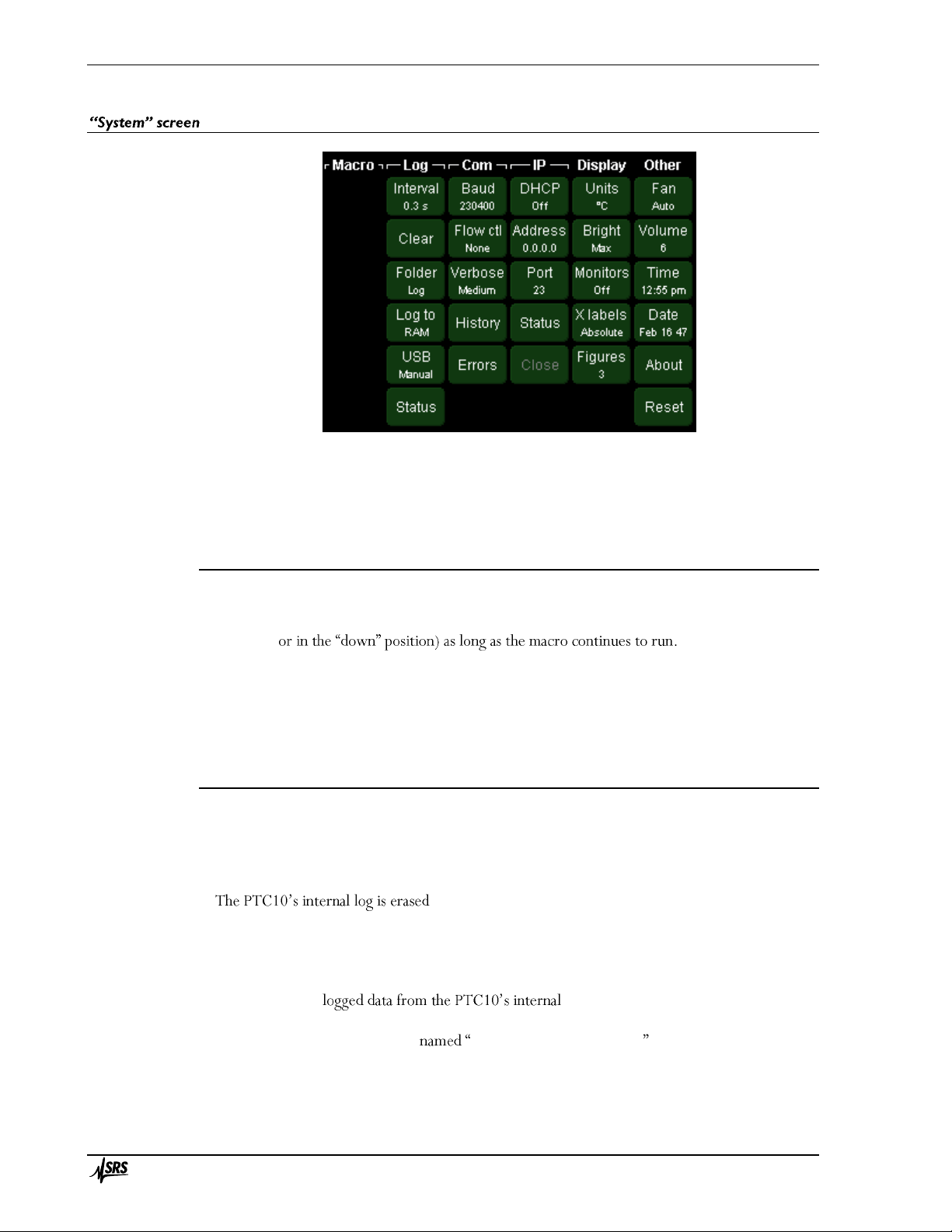
Operation 78
PTC10 Programmable Temperature Controller
The System screen includes controls for all settings that affect the entire instrument. Time and
date, Ethernet and GPIB parameters, and data logging are set up through this screen.
Nothing happens if the System button is pressed when the System screen is already showing.
System screen: Macro column
Buttons with the names of up to six currently-defined macros appear in this menu. Pressing one
of these macro buttons runs the corresponding macro, and the button remains selected (i.e.,
highlighted,
A macro button appears to be selected whenever a macro with the name shown on the button is
running. Touching a selected macro button stops all currently-running macros with that name. See
the Macro Names topic in the Remote Programming section for more information on macro
names.
System screen: Log column
Interval
Sets the default time between log points. Each channel also has its own log interval setting that
can override this default. If the interval is set, for example, to 1 s, the PTC saves a data point once
per second, and each point represents the average reading over one second period.
when the log interval is changed, meaning that accumulated
data will disappear from the plot. Data logged to a USB memory stick is not erased.
Clear
Erases logged data. There are three options:
RAM deletes all memory.
USB deletes all log files (not just the current file) from the log folder on the external USB
memory stick. Specifically, all files \<folder>\XX\LogYY.csv are deleted, where
<folder> is the folder name specified by the Folder button, and XX and YY are two-digit numbers.
All is the same as selecting RAM and USB.
Page 95

Operation 79
PTC10 Programmable Temperature Controller
Folder
Sets the USB device folder into which the PTC10 writes log files. If the folder does not exist, it is
created. If the folder does exist and contains PTC10 log files, the PTC10 appends data to the
highest-numbered log file.
Log to
Enables or disables logging to a USB memory device. I to the
USB device and also stores the data in its internal memory the PTC10 stores data
in its internal memory but not on the USB device. store data
at all, and the plots on the Plot screen are always empty.
USB logging can also be enabled or disabled by touching the red USB Logging indicator in the
top-right corner of the screen.
If the USB device is unplugged, the System.Log.Log To
to indicate that data is no longer being written to USB.
USB
I o , the PTC immediately starts logging data
plugged into the instrument. The System.Log.
SB
a USB flash key or hard drive with available memory plugged into the PTC, data will be logged to
it.
If set to , when a USB device is plugged in, the user must touch the red USB logging
indicator to start logging data to the device. The System.Log.Log To button automatically switches
n a USB device is
plugged in. If you unplug a device and plug it back in, the PTC stops logging data to the device and
newly-acquired data is not permanently saved.
Status
Shows the name and size of the current log file. The information is updated every 5 seconds.
When the size reaches 100%, a new log file is created.
System screen: COM column
RS -232
Sets the RS-232 baud rate. The RS-232 interface always has 8 bits, 1 stop bit, and no parity.
GPIB
Sets the primary GPIB address. The address must be a value between 0 and 31, inclusive, but in
most GPIB systems 0 is reserved for the controller-in-charge and should not be used.
Verbose
Determines how the PTC10 responds to RS-
PTC10 only sends messages in response to queries. This mode should be selected for IEEE488.2
s
a message in response to each instruction that sets or gets a parameter, and the message includes the
parameter name. Example responses are shown in the table below.
Response to
Page 96

Operation 80
PTC10 Programmable Temperature Controller
Verbose
level
2A?
xyz
2A = 37.47
Low
37.4722
(no response)
(no response)
Medium
37.4722
(no response)
High
2A.Value = 37.4722
2A.Value = 37.47
History
This button brings up a window that that shows the contents of the last twelve messages sent or
received over the COM ports. The window is helpful for debugging communications issues.
Errors
This button produces a window that shows the last six errors caused by COM port
communications.
Close
Closes the Ethernet port. The PTC10 only accepts
possible to switch between Telnet and UDP without closing the port.
The Close button is greyed out when the Ethernet port is not in use. Once a Telnet connection is
made or a UDP packet is received, the Close button is un-greyed, indicating that the PTC10 is
bound to a client computer and will not accept macros from any other computer until the Close
button is pressed, the PTC10 is rebooted, or the client closes the telnet connection.
System screen: IP column
DHCP
DHCP server is present on the network, the other IP settings are automatically configured and are
grayed out.
Address
Sets the IP address. The button is greyed out if DHCP is enabled.
Port
Sets the telnet port for Ethernet communications. Remote commands can be sent to the PTC
through a telnet connection or a raw UDP stream addressed to the selected port. The port must be
a value between 0 and 65535, inclusive, and should normally be either 23 (the default) or a value
greater than 1024.
Status
Shows the status of the Ethernet interface.
up/down at 10/100/1000 Mbps: if the link is up, that means the PTC10 is physically
connected to a network.
hardware problem.
Max frames received: the PTC10 has a queue of unprocessed Ethernet packets, and this value
is the longest that the queue has gotten in last 5 seconds. If this number reaches 40, that
means Ethernet data is being received faster than the PTC10 can process it.
Page 97

Operation 81
PTC10 Programmable Temperature Controller
Remote IP: shows the IP address of the remote system that the PTC10 is accepting
commands from. If this is n , press the
have the PC send a command.
Indicates which protocol the PTC10 is using to communicate with
the PC. se, touch the Close button and then have
the PC send a command using a different protocol.
The status of the TCP connection. Normally the state is either listen , which
means the PTC10 is waiting for a connection, or established , which mean
active connection.
me sort of network incompatibility.
The state of the process that automatically assigns an IP address to the PTC10. The
state is n s turned off or
another state for more than a few s
communicate with the DHCP server.
Close
The PTC10 only accepts messages from a single computer and only in a single protocol (Telnet
or raw UDP stream). To change the computer or the protocol, press the Close button.
The Close button is greyed out if Telnet
received any UDP packets addressed to the active port .
is being used and the computer
closes it.
System screen: Display column
Units
Sets the temperature units for the entire instrument. Temperature measurements are both
displayed and logged in the specified units. If the units are changed in the middle of an experiment,
there will appear to be a large jump in all of the temperature records. PID setpoint values are not
adjusted to compensate for the new units.
Five units options are available: °C, K, mK, °F, and Sensor. If the Sensor option is selected,
sensor measurements are not converted to temperature and instead appear in the native units of the
sensor, i.e. millivolts for thermocouples, volts for diode sensors, and ohms for resistive sensors.
Bright
S
turned on again for 2 seconds by touching the screen.
Monitors
Most els that can show additional information about the card or
the status of its I/O channels. For example, most cards have an onboard sensor that measures the
temperature of the card itself. Cards that are intended to drive resistive heaters have a channel that
shows the resistance of the heater, and may also have channels that show the heater voltage and
current. While not typically needed for normal day-to-day use, these monitor channels can be very
useful when debugging performance issues.
To save memory and processor time, the monitor channels are disabled by default. They can be
enabled by touching the button and then selecting from the pop-up menu. The
monitor channels will then appear on the Select screen like any other ll be logged to
Page 98

Operation 82
PTC10 Programmable Temperature Controller
internal memory and to a USB stick (if USB ll appear in the response
to the
t appear on the Select screen
still logged internally and to the
mmands. In
particular, the monitor channels are removed from the response to the getOutput command, while
nnels.
X labels
more concise, easy-to-read labels that indicate the amount of time between grid lines. The elapsed
time is reset to zero once per minute, hour, or day, depending on the X range of the graph.
Absolute X labels
Elapsed X labels
Page 99

Operation 83
PTC10 Programmable Temperature Controller
Figures
Sets the maximum number of figures that are shown after the decimal point for all channel
values. Fewer digits may be shown if the fit into the available space. This
setting does not affect logged data, PID feedback, or plots.
Each channel also has its own Figures setting that can override this global setting.
Cal
Calibrates the touchscreen. When this button is pressed, two crosses are displayed. Touch both
crosses to calibrate the location wh
calibration is cancelled after 15 seconds.
In this case, send the command -232, Ethernet, or GPIB port to
activate the calibration feature.
System screen: Other column
Fan
Controls the speed of the front-panel fan. If a PTC430 DC output card or PTC440 TEC driver is
being used, the fan should generally be set to Max or Auto, otherwise the card may overheat and be
permanently damaged. The accuracy of temperature measurements may be reduced if the fan is
disabled.
Volume
Sets the speaker volume. The volume affects all sounds played, including alarms.
Tim e
The system time. Changing the time does not affect time stamps on previously-acquired data
points. Therefore, if the time is advanced by one hour, a one-hour gap appears in the plot.
Conversely, if the time is set back by one hour, any data taken over the last hour is no longer
plotted, and newly-acquired data appears in its place. The data is not actually erased from the USB
Date
The system date. Changing the date can affect the display of previously-acquired data; see the
About
Displays a text box with information about the firmware version and installed I/O cards.
Reset
Resets one of the following:
Running macros: stops all running macros. Has no effect on saved macros.
Saved macros: deletes all saved macros from local memory. Does not delete macros from
USB memory devices. Has no effect on running macros.
Display
Returns the front panel to the Select menu, de-selects all channels in all groups, and erases
locally-stored log data (data on USB drives is not affected). Returns all plots to autoscaled X
and Y with a 1 minute X range and changes the plot location of all channels to 1. If a *TRG
Page 100

Operation 84
PTC10 Programmable Temperature Controller
remote command was previously received, re-enables automatic A/D conversions. Hides
internal monitor channels.
Ports: Closes all I/O ports and re-opens them. USB and Telnet connections are lost. The port
settings (baud rate, IP address, etc.) remain unchanged.
Port settings: Resets all I/O port settings to their factory defaults.
Channels: Resets the settings on the Channel menu for all channels to their factory defaults.
Also sets the A/D rate to 100 ms.
Log: Resets the default log rate to 1 second, sets the log rate for each channel to the default,
and enables automatic logging to USB. If a USB storage device is attached, erases log files in
the root directory and begins logging to USB.
All: resets all of the above items.
 Loading...