

Page 1

Wireless Controller for
Low Voltage Hoist
Instruction Manual
Models:
GMC12-WLV-3H24, -12H6
GMC8-WLV-2H24
version 1.0 since 6 November 2018
ATTENTION!
This instruction manual contains important information about the installation and the use of
the equipment. Please read and follow these instructions carefully.
Always ensure that the power to the equipment is disconnected before opening the
equipment or commencing any maintenance work.
GMC12-WLV-3H24_en_manual_M237
(1 /16)
Page 2

Safety information
IMPORTANT INSTRUCTIONS
All safety and operating instructions should be read before the equipment is installed or operated.
IMPORTANT SAFETY INFORMATION
The following general safety precautions have to be observed during all phases of operation, service,
and the repair of this equipment. Failure to comply with these precautions or with specific warnings
in this manual violates safety standards of design, manufacture, and the intended use of this
equipment.
Do not operate in an explosive atmosphere!
Do not operate this equipment in the presence of flammable gases or fumes. Operation of any
electrical instrument in such an environment constitutes a definite safety hazard.
Water, moisture, heat and humidity
Do not operate this equipment near water or in areas with wet floors or in high humidity atmosphere,
where condensation forms on the equipment. It should never be placed near or over a heat register
or other source of heated air and it should not be installed or operated without proper ventilation.
(2 /16)
Page 3

Functions and Control
Motor Controller has been designed to control from 1 to 12 electrically compatible motors, either
separately or simultaneously – controlled via switches located on front panel or wireless
remote/pendant. Optionally you can link GO/STOP button by link connector.
Each device is equipped with unique APA /Automatic Phase Align/ module that guarantees that on
any alignment of input phases the motors will move in the correct direction. If any line wire is
disconnected, the hoist controller stops to ensure safe operation. Unit is also equipped with AVM
/Automatic Voltage Metering/ module. This module checks the main voltage for AC400V +-20% and
the star configuration. if there is any problem with the main voltage, you’re notified, and unit will not
run any hoist.
Unit will not work when:
One phase is missing
Under-voltage is present on lines
Over-voltage is present on lines
All electrical components carry their own individual cSA/UL, CE and comply with European Directives.
The components are housed in robust steel 19" rack casing with powder coating. Complete unit
complies with the CE according the Certification of conformity attached to this manual.
Operation
The motors/hoists connected with the GMCseries controller can be activated individually or
simultaneously using the GO switch located on the front panel or wireless remote. Units can be
optionally linked together to create bigger systems.
How to start
Connect the CEE32/5p plug to the AC400V +-20% power supply – turn the key to ON
position. When the main power is OK, the power LED will light green, otherwise the unit is
OFF. Check phase voltages, frequency and contact the manufacturer if help is needed.
Connect the plugs for the electric hoists to the output sockets.
Check that the emergency STOP mushroom on the device is not engaged or any other linked
device in system.
Move lever on the front panel or WMC remote corresponding to each motor to the required
position:
o UP - Lever in upper position
o STAY – Lever in middle position
o DOWN - Lever in lower position
Pushing the GO button will activate the motors to move simultaneously
Releasing the GO button will stop the movement of the motors simultaneously.
When the device is not being used, it is highly recommended to turn it OFF by the key
located on the front panel.
(3 /16)
Page 4
To Move a single/several hoist(s):
Set the UP/DOWN toggle switch for certain motor to the desired direction. The associated
LED should light green for UP, or red for DOWN direction
Hold the GO button until the motor is moved the desired height, then release.
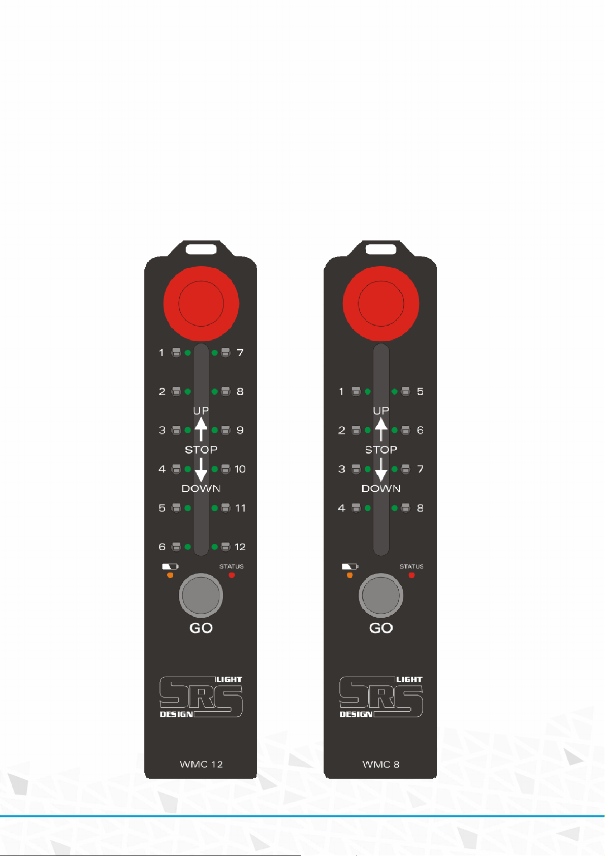
WMCseries remote controller
WMCseries remote allows control of the device via wireless connection.
(4 /16)
Page 5
STOP:
This latching pushbutton switch turns the Hoist Control system off. Once the STOP button has been
pressed, it locks the unit to OFF position and must be rotated clockwise and released before
disengaging.
GO:
This pushbutton switch turns the selected channels of Hoist Control system ON, when the unit is
active. Once the GO button has been pressed, the energizing of the hoists is ON. The backlight of GO
button in local mode on the Base unit is ON only when one or more direction switches are in active
position /UP or DOWN/.
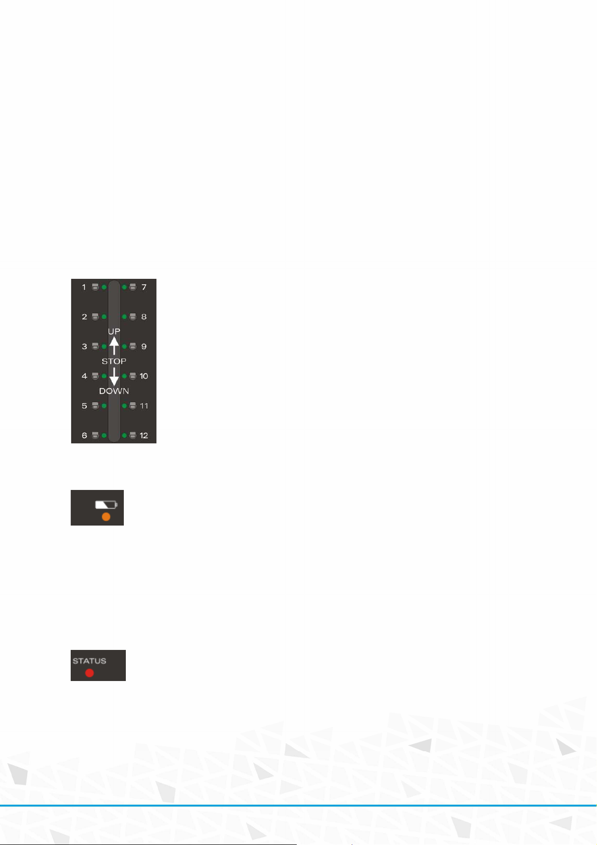
DIRECTION SWITCHES:
They allow changing of the direction of movement for each motor/hoist separately:
BATTERY STATUS LED:
Battery status LED indicator:
Green: 100-90%
Orange: 90-10%
Red: 10%
Red + beep: 5%
REMOTE STATUS LED:
Status LED indicator of WMC remote unit:
Green: Power ON
Green blinking: Power ON – SLEEP - move the direction switch or press GO button to resume
from sleep. This status becomes after 3 minutes of inactivity.
Orange: Indicates direction switch activity
Red: GO button is pressed – sending commands to the Base unit
(5 /16)
Page 6

Link of WMC remotes:
Up to two WMC remotes can be linked together to group the operation of STOP and GO buttons. To
link two WMC units, 5-pin miniXLR cable with custom wire connection is needed.
Never use 1:1 cable – remotes can be destroyed.
When WMC remotes are linked, the GO and STOP buttons are linked – so press of any STOP and GO
button will work for both linked devices.
Link of Base WLV units:
Up to 30 Base units can be linked via link connector located on the front panel.
To link two WMC units, 5-pin DMX data cable is needed.
Due to safety requirements, the link function works only in LOCAL / LINK MODE
of the controller.
(6 /16)
Page 7
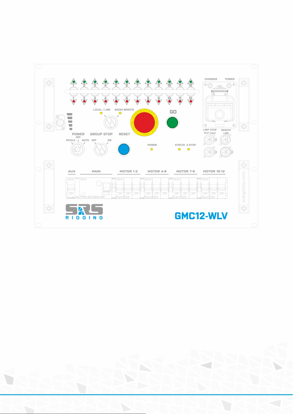
GMC12-WLV series Base unit
GMCseries front panel
Hoist protection:
GMC12: Each three hoists are protected by single C16/3p MCB
Power key switch positions:
OFF: Power OFF /Only battery charger is active in this state/
PICKLE: Power to the hoist is enabled
AUTO: Power to the hoist is enabled when GO command is received
GROUP STOP key switch positions:
OFF: Trip of any breaker or mains GFI breaker will not cause E-STOP
ON: Trip of any breaker or mains GFI will cause E-STOP of the unit
MODE key switch positions:
Local / LINK: Device works via local control or via network in linked operation
Radio Remote: Device is controlled via wireless radio remote
RESET:
RESET button works for the SIL3 E-STOP relay reset. RESET needs be pressed every time after the
unit is turned ON, the E-STOP mushroom has been pressed or when the GROUP STOP has been
activated.
(7 /16)
Page 8

EMERGENCY STOP:
E-STOP is a red color mushroom. Once the E-STOP button has been pressed, it locks the unit into
active position and must be rotated clockwise and released before disengaging. After engaging the
E-STOP button, the RESET button needs to be pressed to reset the system.
GO:
This green pushbutton turns the selected channels of Hoist Control system ON when is active. Once
the GO button has been depressed, the energizing of the hoists is turned OFF.
DIRECTION SWITCHES:
They allow changing the direction of movement for each motor/hoist separately or in groups. LED
close to the switch indicates the movement direction.
Charger status LED:
Status LED of charger located on the front panel is
Green: Battery is fully charged
Green blinking: Battery is charged to 90% or greater capacity
Orange blinking: Not in rapid mode – waiting to be charged
Red: Battery is in rapid charge mode
Red blinking: Battery is ultra-rapid charge mode
No LED: Battery is not inserted
Limit STOP input:
LIMIT STOP connectors for external E-STOP from NLP device.
Link input:
Link input for linking of GMC units.
(8 /16)
Page 9

GMCseries rear panel
(9 /16)
Page 10

Pin Function
1 L1
3 L2
4 L2
6 L3
7 M2 down
9 M2 UP
10 M4 down
12 M4 UP
13 L1
15 L2
16 L2
18 L3
19 M1 down
21 M1 UP
22 M3 down
24 M3 UP
Body
PE
MAINS:
Mains input on 1.5m cable + fuse for mains transformer T2.5A.
AUX output:
AUX output for additional AC230 powered devices. Protected by C16/1p breaker on the front panel.
Output connectors wiring
Harting 24 Female
2 L1
5 L3
8 M2 common
11 M4 common
14 L1
17 L3
20 M1 common
23 M3 common
(10 /16)
Page 11
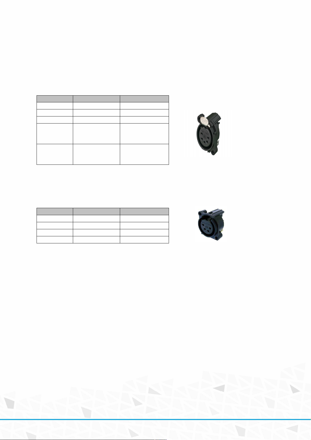
Remote/link connector
Neutrik NC5-MAH/FAH
Connectors are used for a link operation of LV unit or for an additional digital remote CMC-xx-DIGI
connection. Up to 30 units can be linked. They are then controlled via one GO and E-STOP button in
the local operation mode.
Pin Function note
1 Data CMN Data Common
2 Data - Data Minus
3 Data+ Data Plus
Power supply for
CMC
4 DC1
5 DC2
DC12-36V
Power supply for
CMC
DC12-36V
Loadcell E-STOP connector
Neutrik NC4-FAH
Pin Function note
1 DC24-36V Connected to 3
2 Active 1 Active line 1
3 DC24-36V Connected to 1
4 Active2 Active line 2
Both safety lines are separate and NO /normally open/.
Load-cell E-STOP activation contacts must be in NC /normally closed/ state for E-STOP activation.
To reset the load-cell E-STOP function, please cycle the E-STOP mushroom on the device.
(11 /16)
Page 12

Technical data
Mains input AC400V +-20% 50/60Hz
Mains Plug: CEE32A/5p
Protections and Safety:
Short-circuit protection of group of hoists by automatic circuit breakers C20A
APA – Automatic Phase Align
AVM – Automatic Voltage Metering
Double mechanical blocking contactors
Double - Recessed Emergency STOP with SIL3 certification
Housing:
Body: 1.5mm steel housing with gray powder coating
Front panel: 3mm steel housing with gray powder coating
Dimensions /W x D x H/:
GMC12-WLV-3H24: 8U box
Warranty
GMCseries hoist controller comes with a 2-year manufacturer’s warranty. For extended warranty
conditions, please contact the manufacturer at sales@srs-group.com.
The warranty covers the original factory installed components of the controller and their correct
functioning.
The warranty voids if:
any part or replacement components is installed or modified without authorization from the
manufacturer and/or the internal circuit is tampered or modified, and/or the controller is
operated outside normal use conditions
electrical power supply does not conform or there is a connection error or mechanical
damage of the controller, including overload and improper use.
The manufacturer always helps you to repair your unit.
(12 /16)
Page 13

Declaration of conformity
DECLARATION OF CONFORMITY
According to guide lines 89/336 EEC and 92/31 EEC, 90/337 CEE Annex II A:
Name of producer:
Address of producer:
www.srs-group.com/sales@srs-group.com, +421244681417
Declares that the product
Name of product: GMCseries
Types
MC12-WLV-3H24: Low voltage hoist/motor controller
:
Corresponds with following harmonized standards:
Safety:
EMC:
EN 60065
EN 60950
EN 60204-1
EN 13850
EN 12100-2
AS/NZS 3820
EN55103-1, resp. EN55103-2
And
Is in compliance with following requirements:
Machinery directive
: 2006/42/EC
Low Voltage directive:
Bratislava, 04 May 2016
SRS Group s.r.o.
Rybnicna 36/D, SK- 83106 Bratislava, Slovak Republic
hoist controller: GMC12-WLV + GMC8-WLV + variants
2006/95/EC
Robert Sloboda
(13 /16)
Page 14

(14 /16)
Page 15

(15 /16)
Page 16

Copyright 2018 SRS Group s.r.o. | Specifications subject to change without notice.
Document:GMC12-WLV-3H24_en_manual_M237 | Version1.0| Actual as of: 6 November 2018
SRS Group s.r.o.
Rybnicna 36/D | 831 07 Bratislava | Slovakia
Phone: +421 2 44 681 417 | Fax: +421 2 4468 1419
Email: sales@srs-group.com | www.srs-group.com
(16 /16)
 Loading...