

Page 1
Instruction Manual
Models:
version 1.0 since 2 June 2017
ATTENTION!
This instruction manual contains important information about the installation and the use of the
equipment. Please read and follow these instructions carefully.
Always ensure that the power to the equipment is disconnected before opening the equipment or
commencing any maintenance work.
DSR8W-PRO_en_manual_M077
Wireless DMX
Transmitter/Receiver/Splitt
DST8W-3 PRO, DST8W-5 PRO
DST8W-C PRO
Page 2
IMPORTANT SAFETY INFORMATION
The following general safety precautions have to be observed during all phases of
operation, service, and the repair of this equipment. Failure to comply with these
precautions or with specific warnings in this manual violates safety standards of design,
manufacture, and the intended use of this equipment.
Do not operate in an explosive atmosphere!
Do not operate this equipment in the presence of flammable gases or fumes. Operation of
any electrical instrument in such an environment constitutes a definite safety hazard.
Device should never be placed near or over a heat register or other source of heated air
and it should not be installed or operated without proper ventilation.
Mains 85-265V connection
AC power is connected to the splitter via Neutrik PowerCon blue connector. Standard
supply is UNISCHUKO lead with Neutrik PowerCon. Always respect marking of L and N on
connector for correct wiring of Line and Neutral.
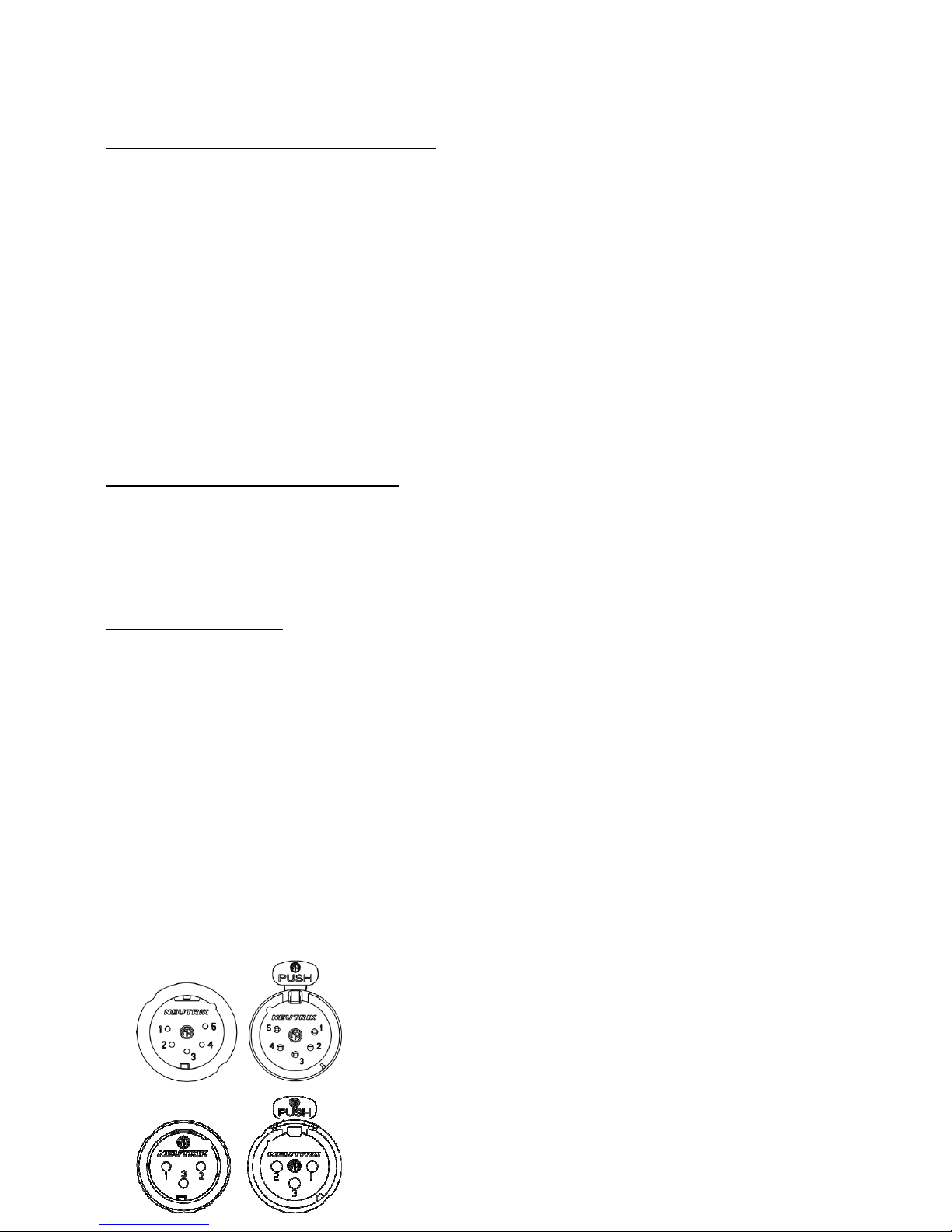
DMX connection
DMX connectors are located on the front panel of the splitter board. These are separated
into two groups. First group is wired in ratio 1:1 and marked as DMX input and DMX thru
and is located on the left side of the splitter. This line is not optically isolated and when
the device is last in line, it must be terminated by the termination button near the DMX
thru connector.
The other part of splitter consists of 8-way optically isolated lines marked with numbers 1-
8. Each line has a separate power supply, line driver and the indication of signals D+ and
D- on both signal lines. These LEDs are active when the splitter is retransmitting the DMX
signal and there is no short circuit between data lines.
In case of short circuit between data pins D+/D- and the CMN pin, the LED connected to
the data line will be off.
Pin 1 Ground / Common
Pin 2 Data -
Pin 3 Data +
Page 3
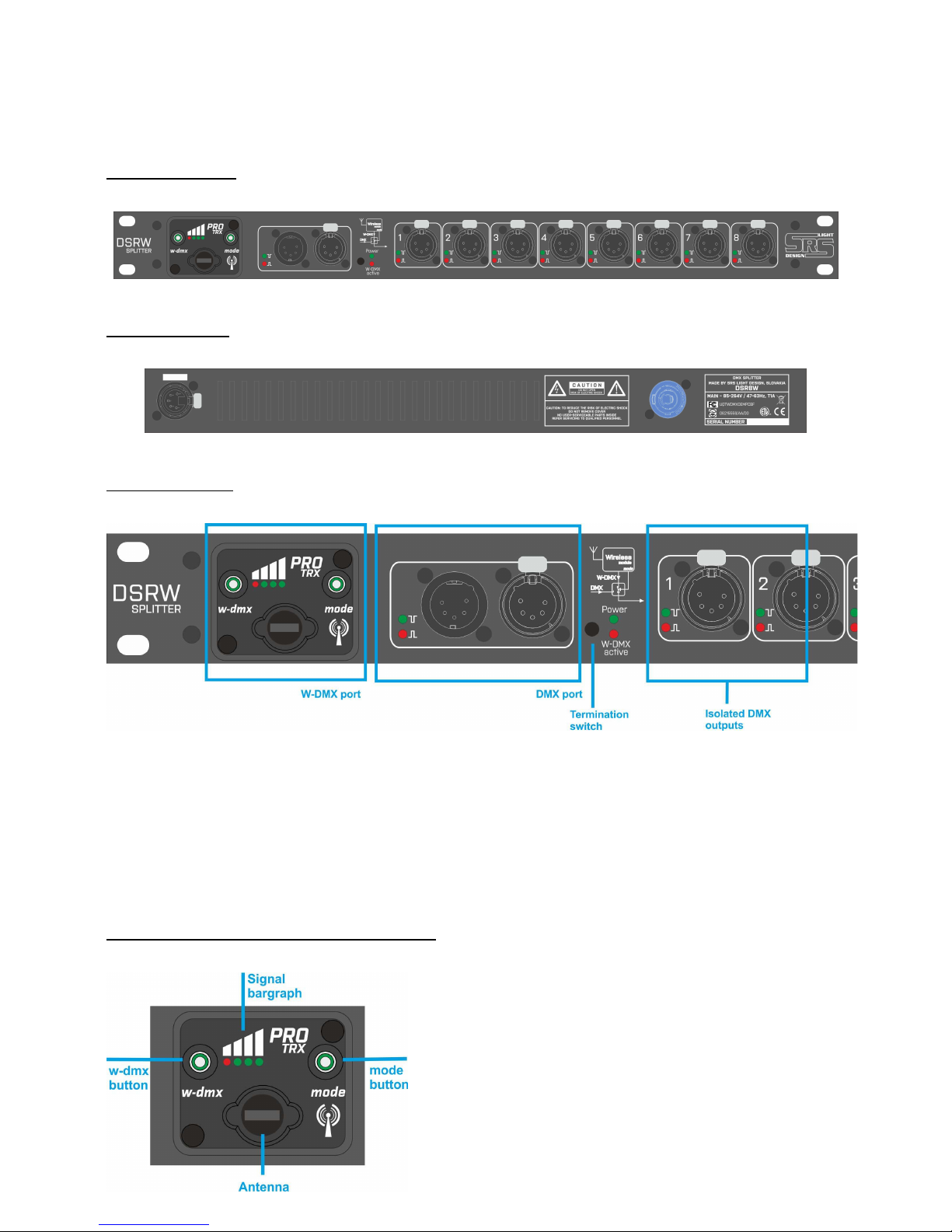
Front panel:
Rear panel:
Device use:
By default, Power LED indicates that DSR8W is on main power. When the power light is
off, check the main power input. DSR8W can be used as usual DMX splitter, W-DMX
receiver or splitter with 8 outputs.
W-DMX signal does not affect the IN/THRU outputs. Cable connection can always be used
as a backup line for the W-DMX data line.
Transmitter / Receiver switch:
One of the two functions (Transmitter/Receiver) of
DSR8W PRO can be selected by holding the W-DMX
button until all lines of bargraph start blinking.
Switching between cycles OFF/TX/RX/OFF is possible
by turning the module on and off and by holding of
the W-DMX button.
Page 4

DMX operation
For the DMX operation, turn off the W-DMX module by holding the MODE button until both
W-DMX and mode buttons are lit in red color. W-DMX module is now turned off. Now just
connect the DMX cable to DMX IN connector and use DSR8W as standard DMX isolated
splitter one to eight. When the DMX signal is connected, LEDs marked as D+ and D- go on
for the input module and output modules 1:8.
W-DMX operation: Receiver
For the W-DMX operation, turn on the W-DMX module by holding the MODE button until
Mode lights in green. The W-DMX function button will indicate the W-DMX functionality
described on the next page. When the unit is in the Receiver mode, the signal bargraph is
showing the W-DMX signal strength. There is an automatic backup of the W-DMX line by
the cable connection. When the W-DMX is linked to the transmitter, signal quality is good
and the W-DMX active LED is on. When this LED is off, the quality of W-DMX signal is poor
or the Transmitter is turned off. Please check before reconnecting to transmitter.
W-DMX button LED signalization
W-DMX button RX function
• Long press /more than 10s/ – Unlinking from the Transmitter
Page 5

W-DMX operation: Transmitter
For the W-DMX operation, turn on the W-DMX module by holding the MODE button + the WDMX function button until both light in green color + the W-DMX is slowly changing color.
The Transmitter operation is indicated by changing of three green Bargraph LEDs in effect
of transmitting.
You can use the DSR8W PRO as the Transmitter and DMX splitter mode at the same time.
The W-DMX active LED is off while the module is in the Transmitter mode.
W-DMX button LED signalization
W-DMX button TX functions
• Short press /not more than 2s/ – Linking Receivers
• Long press /more than 10s/ – Unlinking from all Receivers
Page 6

W-DMX PRO functions
1. W-DMX is turned off. DSR8W is
used as a DMX splitter. To turn
the W-DMX on, hold the mode
button for 3 sec. To turn it off,
hold the mode button for 5 sec.
2. W-DMX is ready to be linked,
DSR8W works as splitter until
the W-DMX signal is coming to
the W-DMX port. Signal bargraph
is showing the signal strength.
3. W-DMX linked + DMX is missing
on Transmitter. The W-DMX LED
is changing from red to green
slowly and Bargraph is working.
4.
The W-DMX is linked to the
Transmitter and receiving the
DMX signal. Both indicators are
green. Bargraph is working.
Page 7

( 7 / 8)
Device in use / service:
Should there be any problem, do not hesitate to contact us at
sales@srs-group.com or +421244681417 and stay calm. We will help you fix your
problems for sure.
Technical data
Mains input:
AC 100-255V / 50-60Hz / 15W
Input / Output:
8x USITT DMX512 /RS485/ isolated up to 1000V
W-DMX port compatible with W-DMX Transmitters
Size:
1U, Rack-mount metal box with powder coating: 480x183x44.5mm
Weight:
3.6 kg
Temperature of use:
-10
ºC…
+45 ºC
Warranty:
Two-year /24-month/ warranty
DECLARATION OF CONFORMITY
According to guidelines 89/336 EEC and 92/31 EEC:
Name of producer: SRS Group s.r.o.
Address of producer: Rybnicna 36/D, SK- 83106 Bratislava, Slovak Republic
Declares that the product
Name of product: DST8W PRO, 8-way DMX/W-DMX Transmitter/Receiver & Splitter
Type: DSR8W PRO
Corresponds to the following product specifications and R&TTE Directive of the
European Union:
Safety: EN60065, resp. EN 60950
EMC: EN55103-1, resp. EN55103-2
Radio:
EN 301 489-1; 301 489-17; EN 300-328-1; EN 300-328-2
Bratislava, 10 May 2011
Robert Sloboda
Page 8

( 8 / 8)
Copyright 2017 SRS Group, s.r.o. | Specifications subject to change without notice.
Document: DSR8W-PRO_en_manual_M077 | Version 1.0 | Actual as of: 2 June 2017
SRS Group s.r.o.
Rybnicna 36/D | 831 07 Bratislava | Slovakia
Phone: +421 2 44 681 417 | Fax: +421 2 4468 1419
Email: sales@srs-group.com | www.srs-group.com
 Loading...