

Page 1
( 1 / 4)
Instruction Manual
Models:
version 1.0 since 5 July 2018
ATTENTION!
This instruction manual contains important information about the installation and the use of
the equipment. Please read and follow these instructions carefully.
Always ensure that the power to the equipment is disconnected before opening the
equipment or commencing any maintenance work.
DSR5.2-RDM-N_en_manual_M302.doc
DMX Splitter
with RDM Support
DSR5.2-RDM-N
Page 2
( 2 / 4)
IMPORTANT SAFETY INFORMATION
The following general safety precautions have to be observed during all phases of operation,
service, and the repair of this equipment. Failure to comply with these precautions or with
specific warnings in this manual violates safety standards of design, manufacture, and the
intended use of this equipment.
Do not operate in an explosive atmosphere!
Do not operate this equipment in the presence of flammable gases or fumes. Operation of any
electrical instrument in such an environment constitutes a definite safety hazard.
Water, moisture, heat and humidity
Do not operate this equipment near water or in areas with wet floors or in high humidity
atmosphere where condensation forms on the equipment. It should never be placed near or over
a heat register or other source of heated air and it should not be installed or operated without
proper ventilation.
DMX connections
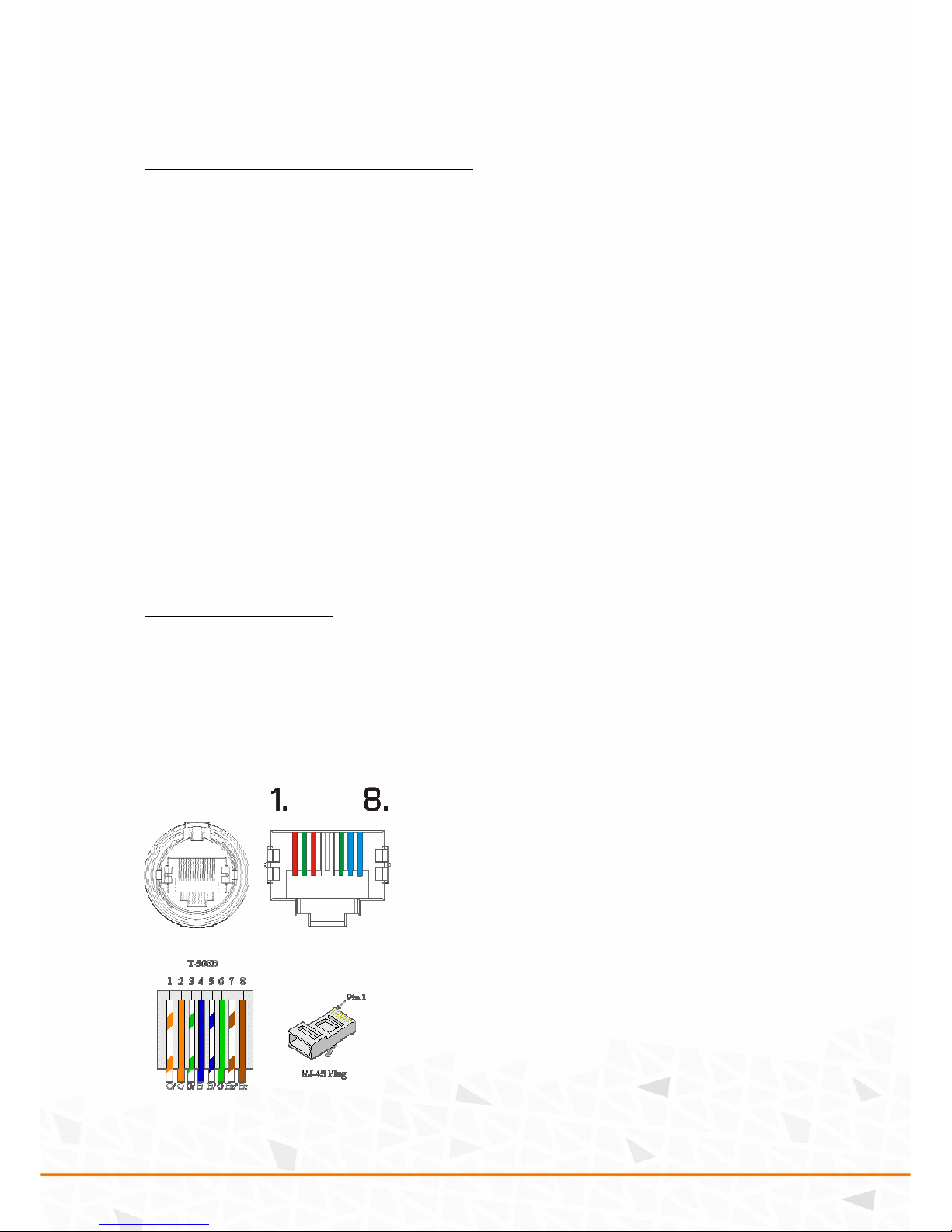
DMX RJ45 connectors are located on the front panel of the device. Splitter consists of DMX in,
thru and outputs marked as A-J. These outputs are optically/electrically isolated and equipped
with RDM filter on each output. Both input lines should be terminated by the termination switch
marked as “120R”. When the line is terminated by the 120R resistor, RED LED indication is on.
There is also a bus line driver indication of signal on both signal lines with two LEDs indicating
the polarity of the DMX signal.
Pin 1, 3 Data +
Pin 2, 6 Data Pin 4, 5 NC
Pin 7, 8 Ground / Common
Page 3
( 3 / 4)
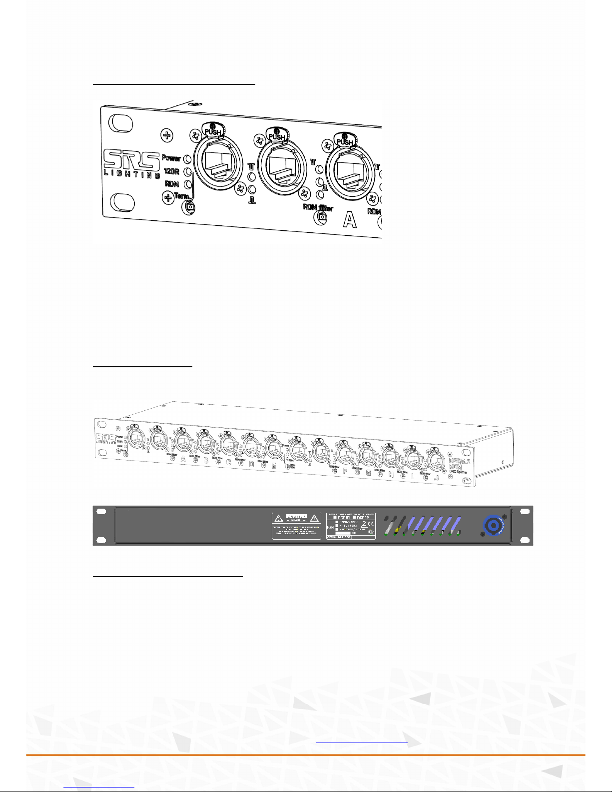
Controls and indication
1. Power indication
2. DMX input signalization
3. DMX input connector channel A
4. DMX Termination switch 120R + signalization LED
5. RDM filter switch + signalization LED
6. DMX data output signalization for positive and negative signal
7. DMX output connector
Device Design
Front panel:
Rear panel:
Device use/servicing:
The Power LED indicator indicates the device is on the main power. All other DATA indication
LEDs being off mean no incoming signal. The termination red LEDs are ON when the termination
switch is activated. Each DMX source is retransmitted to the ten outputs. When there are
connected the RDM devices without RDM support turn the RDM filter on by switch. This is
indicated with the GREEN LED close to the switch.
When the DMX cable is connected to the device, all LEDs marked with symbols D+/D- or the sign
of signal polarity go ON. This indicates that DSR10-RDM is functioning properly and is
retransmitting the input to the outputs. If any of LEDs is off, check the cable first – short circuit
on a line causes the respective LED is off.
Device is upgradeable via USB to DMX cable. Ask on
sales@srs-group.com for more details.
Page 4

( 4 / 4)
Technical data
Main:
AC 100-255V / 50-60Hz / 10W
Input/ Output:
2x USITT DMX512 / RDM
10x USITT DMX512 / RDM amplified
Size:
1U, 19’’, 482.5 x 44.5 x 130 mm
DECLARATION OF CONFORMITY
According to the guidelines 89/336 EEC and 92/31 EEC:
Name of producer: SRS Group s.r.o.
Address of producer: Rybnicna 36/D, SK- 83106 Bratislava, Slovak Republic
Declares that the product
Name of product: Double universe 5-way DMX/RDM Splitter with RJ45 connectors
Type: DSR5.2-RDM-N
Corresponds to the following product specifications:
Safety: EN60065, resp. EN 60950
EMC: EN55103-1, resp. EN55103-2
Additional information:
Unit and all connected apparatuses must be earthed via main cable.
Bratislava, 22 November 2014
Robert Sloboda
Copyright 2017 SRS Group, s.r.o. | Specifications subject to change without notice.
Document: DSR5.2-RDM-N_en_manual_M302.doc | Version 1.0 | Actual as of: 5 July 2018
SRS Group s.r.o.
Rybnicna 36/D | 831 07 Bratislava | Slovakia
Phone: +421 2 44 681 417 | Fax: +421 2 4468 1419
Email: sales@srs-group.com | www.srs-group.com
Weight:
2.1 kg
Package consists of:
DSR5.2-RDM-N unit,
1.5m 3G0.75mm2 PowerCon cable,
Printed manual
Warranty:
Life-time warranty
 Loading...