

Page 1

for Hoist Controller
Advanced Digital Remote
Instruction Manual
Models:
ADR24-DIGI-AHD
ADR36-DIGI-AHD
ADR48-DIGI-AHD
version 3.1 since 7 June 2019
ATTENTION!
This instruction manual contains important information about the installation and the use of
the equipment. Please read and follow these instructions carefully.
Always ensure that the power to the equipment is disconnected before opening the
equipment or commencing any maintenance work.
ADR-DIGI-AHD_manual_M327.doc
( 1 / 18)
Page 2

Safety information
IMPORTANT INSTRUCTIONS
All safety and operating instructions should be read before the equipment is installed or operated.
IMPORTANT SAFETY INFORMATION
The following general safety precautions have to be observed during all phases of operation, service,
and the repair of this equipment. Failure to comply with these precautions or with specific warnings
in this manual violates safety standards of design, manufacture, and the intended use of this
equipment.
Do not operate in an explosive atmosphere!
Do not operate this equipment in the presence of flammable gases or fumes. Operation of any
electrical instrument in such an environment constitutes a definite safety hazard.
Water, moisture, heat and humidity
Do not operate this equipment near water or in areas with wet floors or in high humidity atmosphere,
where condensation forms on the equipment. It should never be placed near or over a heat register
or other source of heated air and it should not be installed or operated without proper ventilation.
( 2 / 18)
Page 3

Operation
The ADR-DIGI-AHD is manufactured from as 24/36/48 channels and it suits as directional remote for
digital controllers. The ADR-DIGI-AHD Motors/Hoists connected to the GMDseries and AHDseries
controller can be activated individually or simultaneously using the GO button located on the ADRDIGI-AHD cable. Unit is also equipped with LCD display and encoder wheel with buttons to simplify
setup and operation of system.
How to start
Connect a 5-pin NC5MXX plug to the remote input of the ADR-DIGI-AHD unit.
Check if the emergency STOP button on both AHD devices is released. If not, this state will
be indicated by the STATUS LED blinking in red color. Check STOP buttons on all connected
controllers. Rotate them clockwise to release and RESET units
Move the lever on ADR-DIGI-AHD corresponding to each motor to the desired position.
According to the position of lever, hoists act as follows:
o UP - Lever in upper position
o STAY – Lever in middle position
o DOWN - Lever in lower position
Pushing the GO button will activate the motors and move them simultaneously.
Releasing the GO button will stop the movement of the motors simultaneously.
When the device is not in use, it is highly recommended to push E-STOP mushroom or TURN
off units via key on front panel of AHD controller
To Move a Single Motor:
Set the UP/DOWN toggle switch for desired motor to the desired direction. The associated
LED will illuminate green for UP and red for DOWN direction.
Hold the GO button until the motor(s) is/are moved to the desired height, then release.
To Move Several Motors:
Set the UP/DOWN toggle switches for each motor to the desired direction. The associated
LEDs will illuminate green for UP and red for DOWN direction.
Hold the GO button until the motors are moved to the desired height, then release.
( 3 / 18)
Page 4
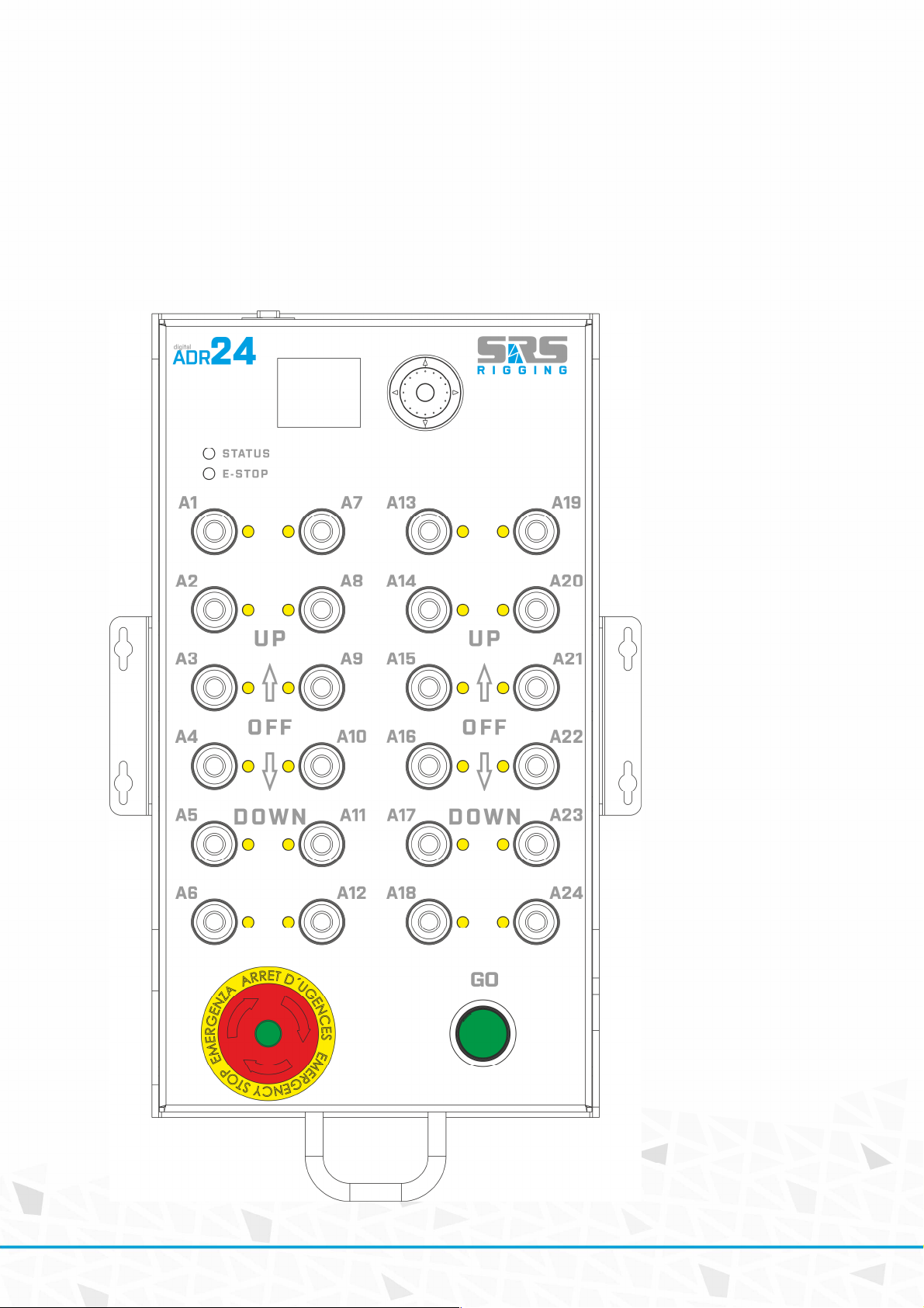
ADR-DIGI-AHD series remote
CMC-DIG-AHDseries remote allows controlling of the AHDseries and GMDseries via digital 5-pin cable
connector. During standard operation, the full 5core cable must be equipped with Neutrik 5-pin
connectors. Maximum cable length is 1000m. The data connection is performed via RS485
communication line.
ADR24--DIGI-AHD with wall-mount ears
( 4 / 18)
Page 5

E-STOP:
This switch protects the operation of the base unit from undesired operation and its press turns the
Controller to an inactive state. E-STOP is a red color button. Once the E-STOP button has been
pressed, system is locked in an inactive position and the button must be rotated clockwise to be
released to continue operation.
GO:
This green button turns the selected channels of Hoist Control system ON when it is active. Once
the GO button has been depressed, the energizing of the hoists is turned off. GO button is blinking
when status of system is activated and you’re able to move hoist
DIRECTION SWITCHES:
They allow changing the direction of movement for each motor/hoist separately or in groups. The
LED located close to the switch indicates the direction of movement.
DIRECTION SWITCH LED
Green UP
Red DOWN
No light stays in position
STATUS LED
GREEN Device ready for action
RED Indicates that the GO button is active
ORANGE Indicates the activity of direction switch, LED blinks in movement
E-STOP LED
GREEN E-STOP system OK
ORANGE Indicates that the system needs to be reset
RED E-STOP is active somewhere in the system
RED blinking E-STOP button is pressed on the device
( 5 / 18)
Page 6
Device menu functions
ENCODER wheel:
This green button turns the selected channels of Hoist Control system ON when it is active. Once
the GO button has been depressed, the energizing of the hoists is turned off. GO button is blinking
when status of system is activated and you’re able to move hoist
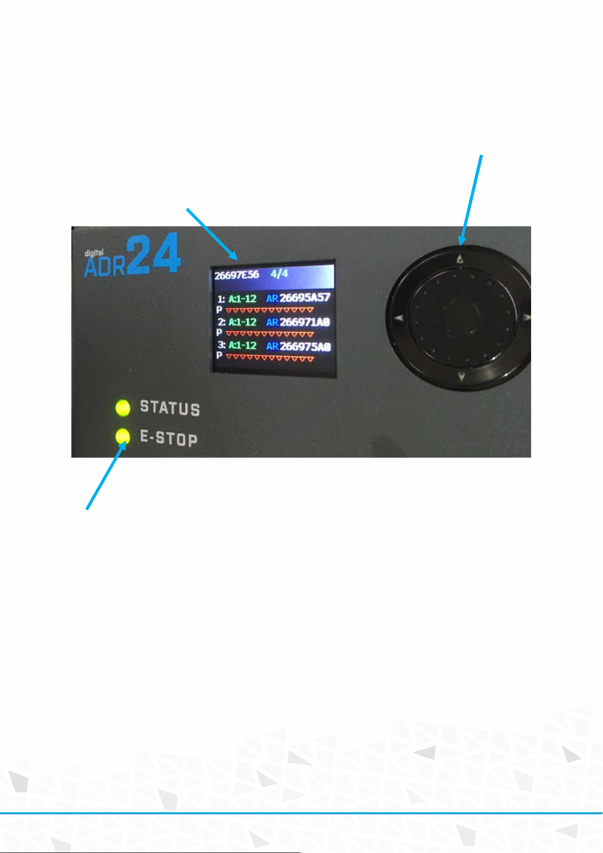
DISPLAY:
TFT display which shown information about remote and also the linked controllers
E-STOP:
This switch protects the operation of the base unit from undesired operation and its press turns the
Controller to an inactive state. E-STOP is a red color button. Once the E-STOP button has been
pressed, system is locked in an inactive position and the button must be rotated clockwise to be
released to continue operation.
( 6 / 18)
Page 7

DISPLAY INDICATION
Remote ID Number of linked and active controllers
ID of controller
AR: Automatic RESET enabled
MR: Manual RESET enabled
P: Pause
G; GO
Arrow down – channel will go down
Arrow up – channel will go up
A:1-12 Address of controller
Device oeration
After connection to the link the device get discovery of connected controllers. The controller and
remote will get paired and remote will become the master of operation. For confirmation of this
operation you need to press E-STOP and release E-STOP.
When device on link is unable to RESET this screen is displayed. SAFETY means that controller ins
unable to reset. Please check GROUP stop status.
( 7 / 18)
Page 8

After this operation device will get reset and ready for operation. Is indicated by the green STATUS
LED and also GREEN E-STOP LED.
For access to the ADR-REMOTE menu please rotate encoder to the TOP ID and hold center button for
cca 3s until display of MENU is shown. During this operation GO command is disabled.
( 8 / 18)
Page 9

Main menu window. You can create LL /locked link of devices/, setup the display parameters and
show the ABOUT the remote screen.
For creation of LOCKED LINK please anter menu LOCKED link. Then all controllers that been
discoverable on lnk will be added to LOCKED LINK. This means that conttoller setup will work only
when all controllers are ONLINE so if you loose one of controller for power down issue, other
controllers operation will be blocked as well.
( 9 / 18)
Page 10

Locked link save operation: Press middle button to save the LOCKED LINK
CLEAR of LOCKED LINK, please enter menu and hold middle button to clear locked link. After this
operation controller will not watch each other on
link
( 10 / 18)
Page 11

Locked link is shown on main screen with 4/4LL which means tat 4controllers from 4 controllers is
online and locked link has been activated:
LOCKED link ERROR: This screen shown that one controller is lost from LINK. Resove by re-connecting
the device again or remove locked link.
( 11 / 18)
Page 12

DISPLAY MENU: YOu can setup backlight setup and time before screen saver will occour. The setup
will protect display as tft is sensible for long time operation. Use carefully.
ABOUT MENU: the about informaiton is displayed
( 12 / 18)
Page 13

CONTROLLER EDIT menu: Use encoder to go to the desired controller. Hold middle button for desired
time and you will enter menu of controller.
Controller menu: IN controller menu you can setup
1. IDENTIFY = will send identify command to controller to easy visual check of what kind of
controller you’re trying to setup
2. ADDRESS = is start address of operation. If you want to controll 24 channels consisting of
2x12 way unit you need to setup the 1st controller to adress=1 and 2nd to address=2. If you
have 3x 8way you need to use adresses 1, 9, 17
3. RESET = this says if controller has AUTOMATIC or MANUAL RESET. When there is automatic
reset enabled the controller will check itself and reset after cca 2 seconds. NO press of RESET
button is needed. When RESET = MANU means that each e-stop need to be resolved by
pressing RESET button of controller front pannel.
( 13 / 18)
Page 14

Wen you send indetify the CMD SEND command is shown:
ADDRESS SETUP screen:
( 14 / 18)
Page 15

RESET SETUP screen:
DEVICE MENU:
( 15 / 18)
Page 16

1 Data CMN
Data Common
Remote connector
Neutrik NC5-FDL
Pin Function note
2 Data - Data Minus
3 Data+ Data Plus
Power supply for CMC
4 DC1
Power supply for CMC
5 DC2
Housing + Dimensions
3mm lightweight aluminum box
DC12-36V
DC12-36V
Warranty
ADR-DIGI-AHD series hoist controller is covered by a 2-year manufacturer’s warranty. For extended
warranty conditions, please contact the manufacturer at sales@srs-group.com.
Warranty covers the original factory installed components of the controller and their correct
functioning.
Warranty voids if any part or replacement components is installed or modified without authorization
from the manufacturer and/or the internal circuit is tampered or modified and/or the controller is
operated outside normal use conditions and if the electrical power supply is not conform or there is
connection error or mechanical damage of controller, including overload and improper use.
We, as a manufacturer, always help you to repair your unit.
( 16 / 18)
Page 17

( 17 / 18)
Page 18

Copyright 2017 SRS Group, s.r.o. | Specifications subject to change without notice.
Document: ADR-DIGI-AHD_manual_M327.doc | Version 3.1 | Actual as of: 7 June 2019
SRS Group s.r.o.
Rybnicna 36/D | 831 07 Bratislava | Slovakia
Phone: +421 2 44 681 417 | Fax: +421 2 4468 1419
Email: sales@srs-group.com | www.srs-group.com
( 18 / 18)
 Loading...