

Model SR775L
Service Manual - S/N 1035+
Part No. MAN775L_100929 Page 1 of 16
by S Instruments, Inc.
Model SR775L
Wheelchair Scale System
Operating and Service
SInstruments, Inc.
Tel: 716-693-5977 Fax: 716-693-5854 URL: www.srscales.com
email: sri@srinstruments.com
Manual
Serial Numbers: 1035+
, 600 Young Street, Tonawanda, NY 14150
Copyright 2010 SInstruments, Inc.

Model SR775L
Service Manual - S/N 1035+
Part No. MAN775L_100929 Page 2 of 16
TABLE OF CONTENTS
TABLE OF FIGURES ......................................................................................................................2
PACKING CHECKLIST - SR775L ................................................................................................3
ASSEMBLY.......................................................................................................................................4
SYSTEM DESCRIPTION AND INTENDED USE .......................................................................5
MAINTENANCE AND CLEANING ..............................................................................................5
STORAGE AND TRANSPORTATION ........................................................................................6
SPECIFICATIONS...........................................................................................................................7
BUTTON FUNCTIONS ...................................................................................................................8
BASIC SYSTEM OPERATION ......................................................................................................9
DISPLAY ERROR CODES ...........................................................................................................10
BATTERY REPLACEMENT .......................................................................................................10
THEORY OF OPERATION .........................................................................................................11
CALIBRATION ..............................................................................................................................12
WARRANTY...................................................................................................................................15
TABLE OF FIGURES
Figure 1: Scale Assembly................................................................................................................ 4
Figure 2: Battery Compartment Cover ........................................................................................ 4
Figure 3: Button Display ................................................................................................................ 8
Figure 4: Battery Compartment .................................................................................................. 10
Figure 5: Calibration Switch........................................................................................................ 12
SInstruments, Inc.
Tel: 716-693-5977 Fax: 716-693-5854 URL: www.srscales.com
email: sri@srinstruments.com
, 600 Young Street, Tonawanda, NY 14150
Copyright 2010 SInstruments, Inc.

Model SR775L
Service Manual - S/N 1035+
Part No. MAN775L_100929 Page 3 of 16
PACKING CHECKLIST - SR775L
Wheelchair Scale System
DESCRIPTION Qty
√
MAST ASSEMBLY 1 ea
BASE ASSEMBLY 1 ea
NYLON INSERT LOCK NUTS 4 ea
PACKAGE OF SIX (6) “D” CELL BATTERIES 6 ea
QUALITY CONTROL CHECKLIST 1 ea
CALIBRATION CERTIFICATE 1 ea
MODEL SR775L MANUAL 1 ea
SInstruments, Inc.
Tel: 716-693-5977 Fax: 716-693-5854 URL: www.srscales.com
email: sri@srinstruments.com
, 600 Young Street, Tonawanda, NY 14150
Copyright 2010 SInstruments, Inc.
Model SR775L
Service Manual - S/N 1035+
Part No. MAN775L_100929 Page 4 of 16
ASSEMBLY
STEP 1: Unpack the scale system and check parts
against the PACKING CHECKLIST. If there are
any missing or damaged parts, call the local sales
representative.
STEP 2: Verify that the serial number on the Display
Assembly (1) and the Base Assembly (3) match.
IMPORTANT: All of the scale systems are calibrated
at the factory as a complete system. Components
should not be interchanged with other systems.
1
# PART NAME
Display Assembly
1
Mast Assembly
2
Base Assembly
3
Ramps
4
Flat Socket Head Cap Screws (4)
5
Battery Compartment Cover
6
Display Assembly Cable Connector
7
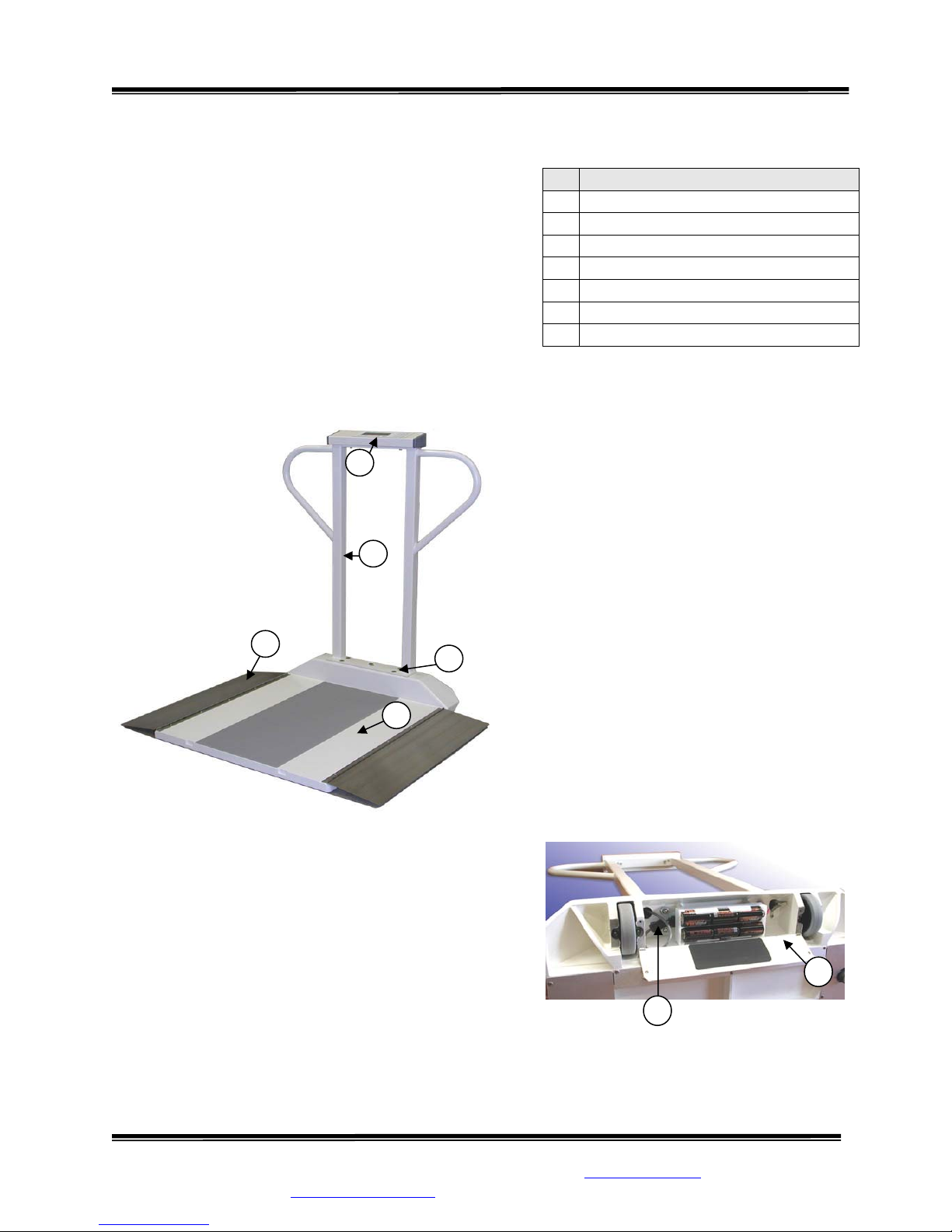
STEP 3: (Figure 1) Place the Mast
Assembly (2) onto the Base Assembly as
shown. Note: Be sure to put Display
Assembly Cable Connector (7) through
corresponding hole in Base Assembly.
2
4
5
3
Figure 1: Scale Assembly
TEP 6: Plug the Display Assembly Cable Connector
S
(7) into its mate in the battery compartment.
STEP 7: Insert the six (6) “D” cell batteries
following
directions on the Battery Compartment Cover. Close and
sec u r e l y s cre w th e B a t t e r y Co mpa r t m e n t Cover into place.
STEP 8: Gently return scale to an upright, level position
on the f
loor.
STEP 4: Insert the four 3/8” Flats Socket
Head Cap Screws (5) provided, to attach
the Mast Assembly to the Base Assembly.
STEP 5: Gently position the scale system
on its side. Lo o s e n t h e battery compartment
cover screws to open the Battery
Compartment Cover (6) (Figure 2).
6
7
SInstruments, Inc.
Tel: 716-693-5977 Fax: 716-693-5854 URL: www.srscales.com
email: sri@srinstruments.com
Figure 2: Battery Compartment Cover
, 600 Young Street, Tonawanda, NY 14150
Copyright 2010 SInstruments, Inc.

Model SR775L
Service Manual - S/N 1035+
Part No. MAN775L_100929 Page 5 of 16
SYSTEM DESCRIPTION and INTENDED USE
SYSTEM DESCRIPTION
The SR775L Scale System employs the latest in microprocessor and load cell technology to
provide precise and repeatable weight data.
The low power microprocessor circuitry derives its power from batteries that will provide up to
400 hours of weight readings before needing replacement. This eliminates the need for an external
battery charger or the danger of a plug-in power supply.
The SR775L also incorporates a keypad tare, which allows the caregiver to preset a predetermined tare value that can represent the weight of the wheelchair, walker, chair, etc., to be
used when weighing the patient. This amount will be automatically subtracted from the gross
weight of patient and equipment so only the net weight of the patient will be displayed and stored
in memory.
The scale comes equipped with dual side ramps to facilitate access when using wheelchair bound
patients. When not in use, or when moving the scale, the dual ramps are folded up and onto the
scale surface.
INTENDED USE
The SR775L is designed for use as a portable patient
weighing system for ambulatory and non-ambulatory
wheelchair bound patients, or those that need to be
supported by a chair or walker. Maximum weight
capacity must not exceed 1000 pounds or 454
kilograms gross weight.
MAINTENANCE and CLEANING
Exercise caution when cleaning the display
window of the SR775L as it is made of
clear polyester and can be scratched by
abrasive cleaners. It is recommended to use
mild soap and water for general cleaning
and disinfecting. DO NOT use vinegar to
clean the display.
DO NOT use pressurized water or steam. The
scale system contains microprocessor circuitry
and strain gauge sensors that may be adversely
affected by exposure to such an environment.
WARNING
DO NOT EXCEED
MAXIMUM WEIGHT LIMIT OF
1000 LB / 454 KG
WARNING
SInstruments, Inc.
Tel: 716-693-5977 Fax: 716-693-5854 URL: www.srscales.com
email: sri@srinstruments.com
, 600 Young Street, Tonawanda, NY 14150
Copyright 2010 SInstruments, Inc.

Model SR775L
Service Manual - S/N 1035+
Part No. MAN775L_100929 Page 6 of 16
STORAGE and TRANSPORTATION
STORAGE
If storing this equipment for extended periods or longer than three (3) months, remove the
batteries. To maintain proper operation of this instrumentation, storage and transport conditions
should not vary outside the following conditions: Relative Humidity 0% to 85%, Ambient
Temperature -10°C to +50°C.
TRANSPORTATION
To transport the SR775L, tilt the scale back and roll on the built-in wheels to another location.
Gently return the scale system to an upright, level position.
SInstruments, Inc.
Tel: 716-693-5977 Fax: 716-693-5854 URL: www.srscales.com
email: sri@srinstruments.com
, 600 Young Street, Tonawanda, NY 14150
Copyright 2010 SInstruments, Inc.

Model SR775L
Service Manual - S/N 1035+
Part No. MAN775L_100929 Page 7 of 16
SPECIFICATIONS
MAXIMUM WEIGHT CAPACITY
PLATFORM SIZE
DISPLAY TYPE
DISPLAY RESOLUTION
ACCURACY
AUTO ZERO
KEYPAD TARE
AUTOMATIC SHUT OFF
AVERAGING
POWER SUPPLY
1000 lb or 454 kg
28 in x 28 in
1 in LCD display screen
0.1 lb/0.1 kg
0.1% +/- 1 digit reading over 200 g
One button operation
Pre-programmable TARE value to allow patient’s net
weight to be viewed
Programmable to (OFF / 60 / 120 / 180) seconds
Automatic digital filter
Six (6) “D” cell batteries
Low battery indicator on Display
OPERATING CONDITIONS
TRANSPORT and STORAGE
Normal operating conditions for this product:
Ambient Temperature Range: 5°C to 35°C
Relative Humidity Range: 0% to 85% (non – condensing)
Avoid exposure to high-pressure water or steam.
Storage and transport conditions should not vary outside
the following conditions: Relative Humidity 0% to 85%,
Ambient Temperature -10°C to +50°C. Remove batteries
if storing for an extended period of time.
SInstruments, Inc.
Tel: 716-693-5977 Fax: 716-693-5854 URL: www.srscales.com
email: sri@srinstruments.com
, 600 Young Street, Tonawanda, NY 14150
Copyright 2010 SInstruments, Inc.

Model SR775L
y
Service Manual - S/N 1035+
Part No. MAN775L_100929 Page 8 of 16
BUTTON FUNCTIONS
Figure 3: Button Displa
ZERO
The “ZERO” button activates scale display and sets the system to zero. When the system
0
is turned on, the display lights all segments on the LCD, shows the software revision level,
and the local gravitational constant. Scale will be in GROSS WEIGHT mode and display
will zero.
LB/KG MODE
The “LB/KG” button factory default setting allows user to toggle between viewing data in
pounds or kilograms. Alternative options can display “pounds only” or “kilograms only”,
deactivating the “LB/KG” button.
WEIGH
The “WEIGH” button starts the scale and displays the pa t i e n t ’ s w e i g h t . T h e display lights
all segments on LCD, shows the software revision level, and the local gravitational
constant, and starts up in the same mode (NET or GROSS) it was in prior to Automatic
Shut Off. Tare data will not be compromised.
HOLD
The “SET TARE” button stores the weight of object prior to that object and patient being
placed together on the scale.
SInstruments, Inc.
Tel: 716-693-5977 Fax: 716-693-5854 URL: www.srscales.com
email: sri@srinstruments.com
, 600 Young Street, Tonawanda, NY 14150
Copyright 2010 SInstruments, Inc.

Model SR775L
Service Manual - S/N 1035+
Part No. MAN775L_100929 Page 9 of 16
BASIC SYSTEM OPERATION
SETTING SYSTEM ZERO
Before placing anything on the scale, ensure it is level and press the “ZERO” button.
0
When the system starts up, the display will quickly test all segments, indicate the software
revision level, and the local gravitational constant. All tare values will be erased and the scale will b e
in GROSS WEIGHT mode. Display will zero. When both the ZERO and STABILITY DETECTION
display symbols are visibl e, weighing ca n proceed. Ambulatory patient can walk on the scale and
the weight will appear on the display. Non-ambulatory patients should not be placed on the scale
until tare is set for any equipment needed by the patient, i.e. wheelchair/chair/walker etc. Refer to
SETTING TARE.
WEIGH
When the system has been set to zero, the “WEIGH” button can be used after the patient is
positioned on the scale. Lock the patient’s wheelchair brake to prevent movement. The
display will indicate the patient’s weight. After Automatic Shut Off, simply press the
“WEIGH” button to re-activate the scale.
Do not leave patient unattended on the scale platform.
CAUTION
SETTING TARE
Place the empty wheelchair/chair/walker (with any blankets or
pillows that the patient may have with them) on the scale platform.
Press the “ZERO” button to tare the object’s weight. The display
will read “0.0”. Remove the wheelchair from the platform. Place
the patient in the wheelchair. Place the wheelchair on the platform. Lock the patient’s wheelchair
brake to prevent movement. Press the “WEIGH” button to display the patient’s weight.
When tare is known for an object, the amount can be pre-set via the keypad. Press the “ENTER”
button to activate the keypad and display any pre-set tare data residing in memory. Enter the numeric
value of the weight of the current tare object. For example, 12.5 kilograms will be entered as 125
(decimal remains fixed).
Press the “ENTER” button again to save the data. The PRE-SET TARE and NET W EI GH T display
symbols will light on the display. The pre-set tare value will be indicated as a negative number until the
patient is positioned on the scale.
The “CLEAR” button, or an Automatic Shut Off, will cancel the pre-set operation if the “ENTER”
button has not already saved tare to memory.
The “WEIGH” button will re-activate the scale after Automatic Shut Off without compromising the tare
data.
SInstruments, Inc.
Tel: 716-693-5977 Fax: 716-693-5854 URL: www.srscales.com
email: sri@srinstruments.com
, 600 Young Street, Tonawanda, NY 14150
Copyright 2010 SInstruments, Inc.

Model SR775L
Service Manual - S/N 1035+
Part No. MAN775L_100929 Page 10 of 16
DISPLAY ERROR CODES
CODE DEFINITION RESOLUTION
Err 1
Excessively large or small
gravitational constant is stored
during calibration
Use a known gravitational constant for the location
of the scale.
Err 2
LoBat
^^^^
vvvv
Excessively large or small Full
Scale is stored during calibration
Re-calibrate using a known calibrated weight.
Battery resource is critically low Batteries must be replaced.
Data input to electronics too high
Remove any weight that may be on the scale,
ensure that the scale is level, and re-zero.
Data input to electronics too low Check the Display Assembly Cable Connection
BATTERY REPLACEMENT
STEP 1: When the batteries are low and need to be replaced, the
LOW BATTERY display symbol will light up on the display.
STEP 2: Gently position the scale system on its side to access the
Battery Compartment.
STEP 3: (Figure 4) Unscrew the two screws holding the Battery
Compartment Cover in place.
STEP 4: Open the Cover and remove and replace ALL of the batteries at
the same time. Replace with six (6) “D” cell batteries following the
instruction on the Battery Compartment Cover.
STEP 5: Check to make sure the display is working correctly by pressing
the “ZERO” or “WEIGH” button to activate the display screen.
STEP 6: Close the Battery Compartment Cover and securely screw into
place.
STEP 7: Gently return the scale to the upright, level position.
SInstruments, Inc.
Tel: 716-693-5977 Fax: 716-693-5854 URL: www.srscales.com
email: sri@srinstruments.com
Figure 4: Battery
Compartment
, 600 Young Street, Tonawanda, NY 14150
Copyright 2010 SInstruments, Inc.

Model SR775L
Service Manual - S/N 1035+
Part No. MAN775L_100929 Page 11 of 16
THEORY OF OPERATION
SR Instruments patient weighing systems are digital scales. Strain-gauge force cells convert the force
of an applied weight into an analog signal. This signal is amplified by an operational amplifier and
converted to a digital signal by an analog to digital converter. The digital signal is transferred to a
micro-controller where it is filtered, converted to appropriate units, and displayed on a liquid crystal
display.
Strain-gauge force cells each contain four strain gauges mounted in a full Wheatstone-bridge
configuration. These bridges convert the physical movement of the force cell, due to the applied mass
on the system, into minute changes in electrical resistance. These changes in resistance produce a
voltage difference across the Wheatstone-bridge. The output of the Wheatstone-bridge is digitized by
a sigma-delta analog to digital converter. The data is transferred to the micro-controller.
The micro-controller averages and filters the digital output of the analog to digital converter, subtracts
the value saved during the system zero operation, and scales the filtered output and then displays the
result on the liquid crystal display. The micro-controller performs a rolling average of data for
continuous weigh and then micro-controller averages the data before locking in on the reading. The
micro-controller can be pl aced in a calibration mode, where the system can be re-calibrated. In the
calibration mode, the calibration, local gravitational constant, and duration of “on” time can be
adjusted. The new factors are stored in non-volatile memory.
SInstruments, Inc.
Tel: 716-693-5977 Fax: 716-693-5854 URL: www.srscales.com
email: sri@srinstruments.com
, 600 Young Street, Tonawanda, NY 14150
Copyright 2010 SInstruments, Inc.

Model SR775L
Service Manual - S/N 1035+
Part No. MAN775L_100929 Page 12 of 16
CALIBRATION
IMPORTANT
CALIBRATION CHECK – A certified technician should perform this procedure.
The load cell and integrated electronics have no user serviceable components and
should not be tampered with for any reason. Re-calibration must be performed
when the seal is broken. Recommendation for calibration check is at least once
every 12 months, or as individual maintenance policy requires.
INITIAL SYSTEM SETUP
When initially set up, calibration is factory set and re-calibration is not needed. The Local
Gravitational Acceleration may have to be re-set for the current geographical location. Automatic
Shut Off is shipped with a factory default of 60 seconds. If a longer period of time (120 or 180
seconds) is desired, then it will need to be re-set. Both of these procedures are found below.
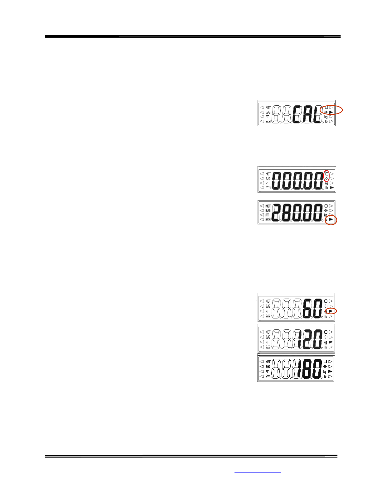
ACCESS SYSTEM SETUP
Ensure scale is level before proceeding. To access all settings below, break the Calibration Seal and
open the right hand end cap. Seal must be replaced by a certified technician. Push the cali brati on
swi t c h right to the “CAL” position (Figure 4) using the eraser end of a pencil or similar item. Display
arrow on the top right will light up.
CAUTION
ESD: The integrated circuits and
semiconductors on the printed circuit boards
may be damaged by electrostatic discharge).
Be sure to use proper handling precautions at
all times.
SETTING GRAVITATIONAL ACCELERATION
STEP 1: Select number “1” on the numeric keypad. The 2ND
display arrow down on the right will light up.
STEP 2: The factory default setting will appear on the display.
Using the keypad, enter in the local gravitational acceleration value if
desired.
STEP 3: Press the “ENTER” button to save the selection or
the “CLEAR” button to exit the menu without saving. The
display arrow will return to the 2
right.
STEP 4: (Figure 5) Select another menu item, or push the
calibration switch left to the “RUN” position to exit
CALIBRATION mode.
ND
display arrow down on the
Figure 5: Calibration Switch
Continued next page
SInstruments, Inc.
Tel: 716-693-5977 Fax: 716-693-5854 URL: www.srscales.com
email: sri@srinstruments.com
, 600 Young Street, Tonawanda, NY 14150
Copyright 2010 SInstruments, Inc.
Model SR775L
Service Manual - S/N 1035+
Part No. MAN775L_100929 Page 13 of 16
CALIBRATION cont’d
CALIBRATION PROCEDURE
Note: Ensure scale is level and make sure that nothing is in contact with the scale during this
procedure. Remove hands from scale when noting displayed calibration results.
STEP 1: Press number “2” on the numeric keypad. The 2ND
display arrow down on the right will light up. System is now in
mode to set Calibration Gravitational Acceleration.
If value is already correct, press the “ENTER” button to save and continue with calibration.
STEP 2: Using the keypad, enter in the local gravitational acceleration value if desired.
STEP 3: Press “ENTER” button to save and continue with calibration. The 4TH display arrow
down on the right will light up.
STEP 4: Press “ZERO” button to set the display to zero. The
ZERO and STABILITY DETECTION display symbols will light
up. At that time, place calibrated weight(s) onto the scale. It is
recommended that the full 280 kilograms be used for calibration.
STEP 5: Using the numeric keypad, enter the value of the total
calibrated weight placed on the scale.
STEP 6: Press the “ENTER” button to save the selection or the “CLEAR” button to exit the
menu without saving. The top right display arrow will light up.
STEP 7: Select another menu item, or push the calibration switch left to the “RUN” position to
exit CALIBRATION mode.
AUTOMATIC SHUT OFF TIMER SETTING
STEP 1: With the calibration switch is in the “CAL” position,
select number “3” on the numeric keypad. The 3RD display arrow
down on the right will light up.
STEP 2: Repeatedly press number “3” on the numeric keypad to
toggle selection for “60” seconds (default), “120” seconds, “180”
seconds, or “--” (off).
STEP 3: Press “ENTER” button to save the new value or
“CLEAR” button to return to the menu without saving. Default (60
seconds) will remain in effect.
STEP 4: Select another menu item, or push the calibration
switch left to the “RUN” position to exit CALIBRATION mode.
SInstruments, Inc.
Tel: 716-693-5977 Fax: 716-693-5854 URL: www.srscales.com
email: sri@srinstruments.com
Continued next page
, 600 Young Street, Tonawanda, NY 14150
Copyright 2010 SInstruments, Inc.

Model SR775L
Service Manual - S/N 1035+
Part No. MAN775L_100929 Page 14 of 16
DISPLAY UNIT OPTIONS SETTING
STEP 1: With the calibration switch is in the “CAL” position, select number “4” on the numeric
TH
keypad. The 4
display arrow down on the left will light up.
STEP 2: Repeatedly press number “4” on the numeric keypad to toggle unit display selections
as follows:
KG/LB (factory default setting). When selected, both display symbols will light up.
Weight readings will display in either pounds or kilograms. Pressing the “kg/lb” button
toggles between display units at any time during the weigh process.
LB only. When selected, the “lb” display symbol will light. Weight readings will display
in pounds only. The “kg/lb” button is deactivated.
KG only. When selected, the “kg” display symbol will light. Weight readings will display
in kilograms only. The “kg/lb” button is deactivated.
STEP 3: Press “ENTER” button to save t he new value or “CLEAR” button to return to the menu
without saving. Default will remain in effect.
STEP 4: Select another menu item, or push the calibration switch left to the “RUN” position to
exit CALIBRATION mode.
SInstruments, Inc.
Tel: 716-693-5977 Fax: 716-693-5854 URL: www.srscales.com
email: sri@srinstruments.com
, 600 Young Street, Tonawanda, NY 14150
Copyright 2010 SInstruments, Inc.

Model SR775L
Service Manual - S/N 1035+
Part No. MAN775L_100929 Page 15 of 16
WARRANTY
FOUR YEAR LIMITED WARRANTY
Each S system is manufactured with high quality components. SR Instruments, Inc.
warrants that all new equipment will be free from defects in material or workmanship, under
normal use and service, for a period of four (4) years from the date of purchase by the original
purchaser. Normal wear and tear, injury by natural forces, user neglect, and purposeful
destruction are not covered by this warranty. Warranty service must be performed by the factory
or an authorized repair station. Service provided on equipment returned to the factory or
authorized repair station includes labor to replace defective parts. Goods returned must be shipped
with transportation and/or broker charges prepaid. SR Instruments, Inc.’s obligation is limited to
replacement of parts that have been so returned and are disclosed to SR Instruments, Inc.’s
satisfaction to be defective. The provisions of this warranty clause are in lieu of all other
warranties, expressed or implied, and of all other obligations or liabilities on SR Instruments,
Inc.’s part, and it neither assumes nor authorizes any other person to assume for SR Instruments,
Inc. any other liabilities in connection with the sale of said articles. In no event shall SR
Instruments, Inc. be liable for any subsequent or special damages. Any misuse, improper
installation, or tampering, shall void this warranty.
DAMAGED SHIPMENTS
Title passes to purchaser upon delivery to Transportation Company. Any claims for shortage or
damage should be filed with the delivery carrier by purchaser.
RETURN POLICY
All products being returned to SR Instruments, Inc. require a Return Goods Authorization number
(RGA). To receive an RGA, call our Technical Service Team at 716-693-5977 or toll-free in the
USA and Canada at 800-654-6360.
When inquiry is made, please supply model and serial numbers, purchase order, if the scale was
bought on contract, and reason for return.
Generally, deleted, damaged, and outdated merchandise will not be accepted for credit. A
minimum restocking charge of 15% will be assessed on return of current merchandise.
All returns are to be shipped FREIGHT PREPAID to: SR Instruments, Inc., 600 Young Street,
Tonawanda, NY 14150.
RESTOCKING FEE
• 15% fee for any scale that has been opened and used
• 10% fee for any scale returned that has been ordered incorrectly or refused delivery with
no model change
• 5% fee if an error in ordering has been made and a different model exchanged
• No fees will be charged if the scale is returned because of an error on the part of SR
Instruments, Inc.
• No returns accepted after 60 days.
SInstruments, Inc.
Tel: 716-693-5977 Fax: 716-693-5854 URL: www.srscales.com
email: sri@srinstruments.com
, 600 Young Street, Tonawanda, NY 14150
Copyright 2010 SInstruments, Inc.

Model SR775L
Service Manual - S/N 1035+
Part No. MAN775L_100929 Page 16 of 16
By SInstruments, Inc.
Precision & Technology in
Perfect Balance
™
SInstruments, Inc.
Tel: 716-693-5977 Fax: 716-693-5854 URL: www.srscales.com
email: sri@srinstruments.com
, 600 Young Street, Tonawanda, NY 14150
Copyright 2010 SInstruments, Inc.
 Loading...