

SR Scales Daily-Weigh SR255 Operating And Service Manual

Model SR255 Daily-Weigh Scale
Operating and Service Manual - S/N 3616+
Part No. MAN255_110921 Page 1 of 22
S
by SInstruments, Inc.
Model SR255
Daily-WeighScale
Operating and Service
Manual
Serial Numbers: 3616 +
SInstruments, Inc., 600 Young Street, Tonawanda, NY 14150
Tel: 716-693-5977 Fax: 716-693-5854 URL: www.srscales.com
email: sri@srinstruments.com
Copyright 2011 SInstruments, Inc.

Model SR255 Daily-Weigh Scale
Operating and Service Manual - S/N 3616+
Part No. MAN255_110921 Page 2 of 22
TABLE OF CONTENTS
TABLE OF FIGURES ......................................................................................................................3
PACKING CHECKLIST – SR255– ADULT .................................................................................4
PACKING CHECKLIST – SR255 – PEDIATRIC .......................................................................5
ASSEMBLY.......................................................................................................................................6
REPLACEMENT PARTS AND ACCESSORIES ........................................................................8
SYSTEM DESCRIPTION AND INTENDED USE .......................................................................9
MAINTENANCE AND CLEANING ..............................................................................................9
STORAGE AND TRANSPORTATION ......................................................................................10
SPECIFICATIONS.........................................................................................................................11
BUTTON FUNCTIONS .................................................................................................................12
BASIC SYSTEM OPERATION ....................................................................................................12
BATTERY REPLACEMENT .......................................................................................................15
THEORY OF OPERATION .........................................................................................................16
CALIBRATION ..............................................................................................................................17
INITIALIZATION .........................................................................................................................18
TROUBLESHOOTING .................................................................................................................19
WARRANTY...................................................................................................................................20
NOTES .............................................................................................................................................21
SInstruments, Inc., 600 Young Street, Tonawanda, NY 14150
Tel: 716-693-5977 Fax: 716-693-5854 URL: www.srscales.com
email: sri@srinstruments.com
Copyright 2011 SInstruments, Inc.

Model SR255 Daily-Weigh Scale
Operating and Service Manual - S/N 3616+
Part No. MAN255_110921 Page 3 of 22
TABLE OF FIGURES
Figure 1: Assembled SR255 Daily-Weigh Scale ......................................................................... 6
Figure 2: Stretcher Cup Installed .................................................................................................. 6
Figure 3: Mast Placement and Screw ............................................................................................ 7
Figure 4: Spreader Bar Connected in Receptacle ........................................................................ 7
Figure 5: T-Boom - Lifter Pump Connection ............................................................................... 7
Figure 6: Transducer Connected to T-Boom ............................................................................... 7
Figure 7: Transducer Cable Connection ...................................................................................... 7
Figure 8: Transducer - A-Frame Connected ................................................................................ 7
Figure 9: Velcro End of Stretcher Bar Channel on Stretcher ................................................. 8
Figure 10: A-Frame Hook Placement on Stretcher ..................................................................... 8
Figure 11: Stretcher Cup Receptacle for Transporting Scale .................................................. 10
Figure 12: Lifter Legs Opened/Closed ........................................................................................ 13
Figure 13: Lifter LOCK/ RELEASE Lever .................................................................................. 14
Figure 14: Battery Compartment Cover .................................................................................... 15
Figure 15: PC Board Access Cover ............................................................................................. 17
Figure 16: Location of Internal Calibration Buttons and Offset Potentiometer .................... 17
Figure 17: Location of Internal Initialization Buttons .............................................................. 18
SInstruments, Inc., 600 Young Street, Tonawanda, NY 14150
Tel: 716-693-5977 Fax: 716-693-5854 URL: www.srscales.com
email: sri@srinstruments.com
Copyright 2011 SInstruments, Inc.

Model SR255 Daily-Weigh Scale
Operating and Service Manual - S/N 3616+
Part No. MAN255_110921 Page 4 of 22
PACKING CHECKLIST – SR255– ADULT
DESCRIPTION QUANTITY
Box 1
T-BOOM / MAST with INVACARE LIFTER 1 ea
1/4-20 x 1” SOCKET HEAD CAP SCREW (for Mast Assy.) 1 ea
INVACARE LIFTER BASE 1 ea
3/8-16 x 1 ¼” SHOULDER BOLT (for T-Boom/Pump Assy.) 1 ea
WASHER (for T-Boom/Pump Assy.) 1 ea
3/8-16 LOCK NUT (for T-Boom/Pump Assy.) 1 ea
SPREADER BAR 1 ea
TRANSDUCER TUBE 1 ea
6-32 x ½” SOCKET HEAD CAP SCREW (Safety ScrewTransducer Assy.)
2 ea
STAPH-CHECK STRETCHER (32” x 72”) 1 ea
STRETCHER CUP 1 ea
DISPLAY / BATTERY BOX (pre-attached to mast) 1 ea
SIX (6) “D” CELL BATTERIES 6 ea
A-FRAME 2 ea
3/8-16 x 2 ¼” SHOULDER BOLT (for A-Frame Assy.) 2 ea
3/8-16 LOCK NUT (for A-Frame Assy.) 2 ea
3/16” ALLEN WRENCH 1 ea
7/64” ALLEN WRENCH 1 ea
½” OPEN END WRENCH 1 ea
Box 2
STRETCHER BARS (72”) 2 ea
HARDWARE NOTE: All hardware is already in
position and “finger tight”. No nuts, bolts or screws
are packaged separately.
SInstruments, Inc., 600 Young Street, Tonawanda, NY 14150
Tel: 716-693-5977 Fax: 716-693-5854 URL: www.srscales.com
email: sri@srinstruments.com
Copyright 2011 SInstruments, Inc.

Model SR255 Daily-Weigh Scale
Operating and Service Manual - S/N 3616+
Part No. MAN255_110921 Page 5 of 22
PACKING CHECKLIST – SR255 – PEDIATRIC
DESCRIPTION QUANTITY
Box 1
T-BOOM/MAST with INVACARE LIFTER 1 ea
1/4-20 x 1” SOCKET HEAD CAP SCREW (for Mast Assy.) 1 ea
INVACARE LIFTER BASE 1 ea
3/8-16 x 1 ¼” SHOULDER BOLT (for T-Boom/Pump Assy.) 1 ea
WASHER (for T-Boom/Pump Assy.) 1 ea
3/8-16 LOCK NUT (for T-Boom/Pump Assy.) 1 ea
SPREADER BAR 1 ea
TRANSDUCER TUBE 1 ea
6-32 x ½” SOCKET HEAD CAP SCREW (Safety ScrewTransducer Assy.)
2 ea
STAPH-CHECK STRETCHER (32” x 60”) 1 ea
STRETCHER CUP 1 ea
DISPLAY / BATTERY BOX (pre-attached to mast) 1 ea
SIX (6) “D” CELL BATTERIES 6 ea
A-FRAME 2 ea
3/8-16 x 2 ¼” SHOULDER BOLT (for A-Frame Assy.) 2 ea
3/8-16 LOCK NUT (for A-Frame Assy.) 2 ea
3/16” ALLEN WRENCH 1 ea
7/64” ALLEN WRENCH 1 ea
½” OPEN END WRENCH 1 ea
Box 2
STRETCHER BARS (60”) 2 ea
HARDWARE NOTE: All hardware is already in
position and “finger tight”. No nuts, bolts or screws
are packaged separately.
SInstruments, Inc., 600 Young Street, Tonawanda, NY 14150
Tel: 716-693-5977 Fax: 716-693-5854 URL: www.srscales.com
email: sri@srinstruments.com
Copyright 2011 SInstruments, Inc.
Model SR255 Daily-Weigh Scale
Operating and Service Manual - S/N 3616+
Part No. MAN255_110921 Page 6 of 22
ASSEMBLY
4
3
5
1
2
6
12
7
4
8
10
9
11
13
14
15
15
15
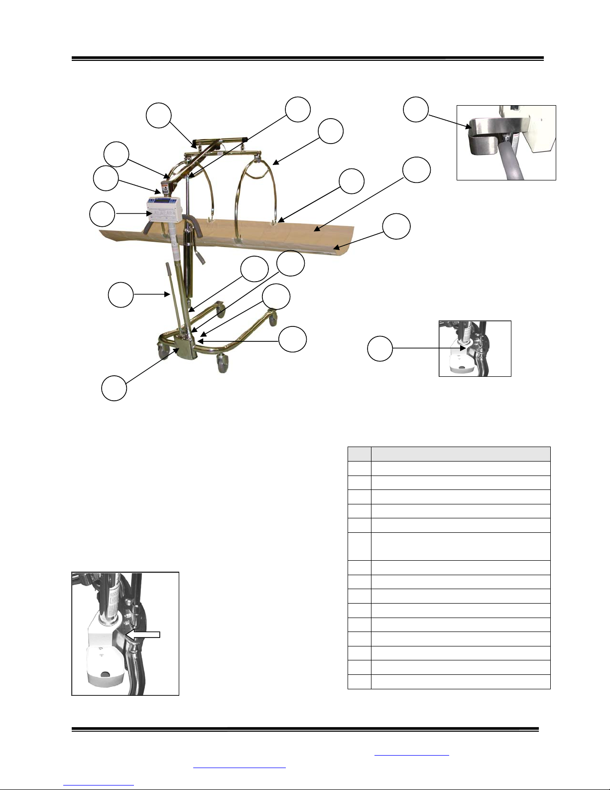
Figure 1: Assembled SR255 Daily-Weigh Scale
STEP 1: Unpack the scale system and check parts
against the PACKING CHECKLIST. If there are any
missing or damaged parts, please call the Service
Hotline: 1-800-654-6360.
STEP 2: (Figure 1) Verify that the serial number on
the Display Unit (3) matches that on the Transducer
Bar (6).
STEP 3: (Figure 2) Attach
the Stretcher Cup (15) to the
Invacare Lifter Base (1),
snapping it into place and
twisting the lower tab back
under the Mast (12), past the
lower bolt.
# PART NAME
Invacare Lifter Base
1
Spreader Bar
2
Display Unit
3
Stretcher Bracket
4
T-Boom (Mast Hinge Connection)
5
Transducer Bar (T-Boom
6
Connection)
Lifter Pump (T-Boom Connection)
7
A-Frame (Stretcher Holders)
8
A-Frame Hook (Stretcher Bar)
9
Stretcher
10
Stretcher Bar Channels
11
Mast
12
Mast Anchor Screw
13
¼-20x1 Socket Head Cap Screw
14
Stretcher Cup
15
Figure 2: Stretcher Cup
Installed
SInstruments, Inc., 600 Young Street, Tonawanda, NY 14150
Tel: 716-693-5977 Fax: 716-693-5854 URL: www.srscales.com
email: sri@srinstruments.com
Continued next page
Copyright 2011 SInstruments, Inc.

Model SR255 Daily-Weigh Scale
Operating and Service Manual - S/N 3616+
Part No. MAN255_110921 Page 7 of 22
ASSEMBLY Cont’d
STEP 4: (Figure 3) Loosen the 1/4-20 x 1 in Socket
Head Cap Screw (14) found on the mast receptacle.
Insert Mast (12) into Invacare Lifter Base (1) as shown.
The bottom of the Mast is slotted. When properly
set, the Mast will drop into place. The Display Unit
(3) will face away from the lifter legs and be
perpendicular to the Invacare Lifter Base. Tighten
Socket Head Cap Screw to secure.
Figure 3: Mast
Placement and Screw
Figure 5: T-Boom - Lifter
Pump Connection
Figure 7: Transducer
Cable Connection
STEP 5: (Figure 4) Insert the Spreader Bar (2) into
the receptacle at the base of the Mast (12). Secure
tightly with screw which is shipped “finger tight” in
place on Invacare Lifter Base.
STEP 6: (Figure 5) Attach and securely tighten
the rod-end of the Lifter Pump (7) to the T-Boom
(5) using 3/8-16 x 1 ¼ in shoulder bolt, washer
and 3/8-16 lock nut. All are shipped “finger tight”
in place on T-Boom. Also tighten the Mast/TBoom hinge lock nut securely.
STEP 7: (Figure 6) Hang the Transducer Bar
from the end of the T-Boom. Label on the
Transducer Bar must face away from unit. Tighten
safety screws as shown to prevent separation of T-
Boom and Transducer Bar.
STEP 8: (Figure 7) Plug in the transducer cable to
the receptacle on the top end of the T- Boom.
STEP 9: (Figure 8) Attach the two (2) A-Frames
(8) to each end of the Transducer Bar using the two
(2) 3/8-16 x 2 ¼ in shoulder bolts and two (2) 3/816 locknuts. Tighten securely.
Figure 4: Spreader
Bar Connected in
Receptacle
Figure 6: Transducer
Connected to T-Boom
Figure 8: Transducer -
A-Frame Connected
SInstruments, Inc., 600 Young Street, Tonawanda, NY 14150
Tel: 716-693-5977 Fax: 716-693-5854 URL: www.srscales.com
email: sri@srinstruments.com
Continued next page
Copyright 2011 SInstruments, Inc.
 Loading...