

Page 1
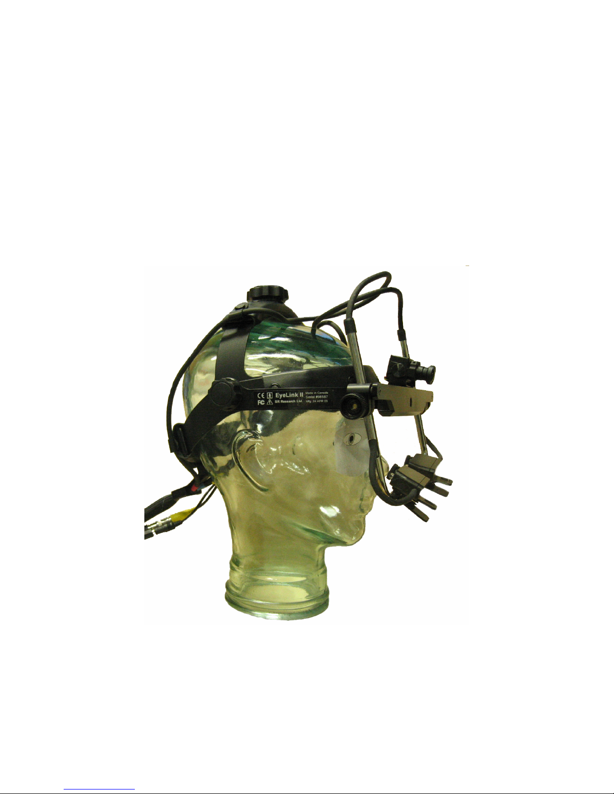
®
EyeLink
II Scene Camera User Manual
(SceneLink Application version 1.2.1)
EyeLink is a registered trademark of SR Research Ltd., Toronto, Canada
Copyright © 2004-2007 SR Research Ltd.
Page 2

Table of Contents
1. Introduction...................................................................................................................1
2. EyeLink II Tracker Application: Scene Camera Components ................................2
2.1 Camera Setup Screen .......................................................................................... 2
2.1.1 Purpose ....................................................................................................... 2
2.1.2 Main Functions ........................................................................................... 3
2.1.3 Key Shortcuts .............................................................................................. 6
2.2 Video Setup Screen............................................................................................. 7
2.2.1 Purpose ....................................................................................................... 7
2.2.2 Main Functions ........................................................................................... 7
2.2.3 Key Shortcuts ............................................................................................ 10
2.3 Scene Camera Alignment Screen...................................................................... 11
2.3.1 Purpose ..................................................................................................... 11
2.3.2 Main Functions ......................................................................................... 11
2.3.3 Key Shortcuts ............................................................................................ 12
2.4 Scene Camera Depth Setup Screen................................................................... 12
2.4.1 Purpose ..................................................................................................... 13
2.4.2 Main Functions ......................................................................................... 13
2.4.3 Key Shortcuts ............................................................................................ 14
2.5 Record Screen ................................................................................................... 15
2.5.1 Purpose ..................................................................................................... 15
2.5.2 Main Functions ......................................................................................... 15
2.5.3 Key Shortcuts ............................................................................................ 16
3. Setting up and Configuring the SceneLink Application .........................................17
3.1 System Requirements........................................................................................ 17
3.2 Installing Scene Camera ................................................................................... 17
3.3 Wiring and Configuration................................................................................. 19
3.3.1 Setting up the Overlay Box ....................................................................... 20
3.3.2 Setting up the Digital Video Converter..................................................... 21
3.3.3 Recording Audio Data .............................................................................. 21
3.3.4 Using a Dell D-Series Laptop as Host PC................................................ 22
3.4 Software Installation ......................................................................................... 22
3.4.1 Host PC..................................................................................................... 22
3.4.2 Display PC................................................................................................ 22
3.5 Checking Firewire Connection ......................................................................... 23
3.6 Configuring SceneLink Options ....................................................................... 24
3.7 Checking SceneLink Connections and Settings ............................................... 26
3.7.1 Seeing Tracker Graphics .......................................................................... 28
3.7.2 Seeing a Gray Screen................................................................................ 28
3.7.3 Seeing a Black Screen............................................................................... 30
4. Performing Recording with the SceneLink Application .........................................32
EyeLink II Scene Camera User Manual © 2004-2007 SR Research Ltd.
ii
Page 3

4.1 Modes of Operation .......................................................................................... 32
4.2 Idle (Preview) Mode ......................................................................................... 33
4.3 Display Area Detection Mode .......................................................................... 33
4.4 Scene Camera Alignment Mode ....................................................................... 36
4.5 Calibration Mode .............................................................................................. 38
4.5.1 Calibration Colors.................................................................................... 39
4.5.2 Physical Coordinates Settings .................................................................. 39
4.6 Depth Correction Mode .................................................................................... 40
4.7 Output Mode ..................................................................................................... 42
4.8 Record Mode..................................................................................................... 43
4.8.1 Problem with Recording ........................................................................... 44
4.8.2 Synchronization with Third-Party Recording Devices ............................. 44
4.8.3 Performing Online Drift Correction......................................................... 45
4.8.3.1 Online Drift Correction from the Display PC....................................... 45
4.8.3.2 Online Drift Correction from the Host PC............................................ 46
4.9 Recording Options ............................................................................................ 47
4.10 Strip Chart......................................................................................................... 48
4.11 Closing Recording Session ............................................................................... 48
4.12 Exiting the SceneLink Application................................................................... 49
5. Data Playback with SceneLink Application.............................................................50
5.1 Opening a Playback Session ............................................................................. 50
5.2 Playing back a Recording Session .................................................................... 51
5.3 Saving a Recorded Trial.................................................................................... 53
5.4 Mapping Gaze Data to Digital Video Coordinates and Getting Frame Number
in the ASC File.............................................................................................................. 54
5.5 Exiting the SceneLink Application................................................................... 55
EyeLink II Scene Camera User Manual © 2004-2007 SR Research Ltd.
iii
Page 4

List of Figures
Figure 2-1: EyeLink II Camera Setup Screen..................................................................... 2
Figure 2-2: EyeLink II Video Setup Screen ....................................................................... 7
Figure 2-3: EyeLink II Scene Camera Alignment Screen ................................................ 11
Figure 2-4: EyeLink II Scene Camera Depth Setup Screen ............................................. 13
Figure 2-5: EyeLink II Record Screen.............................................................................. 15
Figure 3-1: Remove Screws on the Head Camera Bracket............................................... 18
Figure 3-2: Insert Scene Camera between the Head Camera Clamp and the Head Camera
Bracket ...................................................................................................................... 19
Figure 3-3: Dress the Scene Camera Cables..................................................................... 19
Figure 3-4. EyeLink System Connection in a Scene Camera Recording ......................... 20
Figure 3-5: Wiring Diagram for Scene Camera Option.................................................... 21
Figure 3-6. Version of DirectX Installed on the Display PC........................................... 23
Figure 3-7. Error in Detecting the DV Connection........................................................... 24
Figure 3-8. General Tab of the Preferences Dialog Box .................................................. 25
Figure 3-9. Strip Chart Tab of the Preferences Dialog Box ............................................. 25
Figure 3-10. Advanced Tab of the Preferences Dialog Box............................................ 26
Figure 3-11. Openning a Recording Session. .................................................................. 27
Figure 3-12. Initial View of the SceneLink Application .................................................. 27
Figure 3-13. Unzoomed Tracker Graphics ....................................................................... 28
Figure 3-14. Gray Background Over Video, Check EyeLink2 Settings........................... 29
Figure 3-15. Missing Scene Camera Buttons ................................................................... 30
Figure 3-16. Blank Screen in the Video Window............................................................. 31
Figure 4-1. Modes of Operation for SceneLink Recording ............................................. 33
Figure 4-2. Example of Unzoomed Host Screen Overlay ................................................ 33
Figure 4-3. Adjusting the Size of Overlay Display.......................................................... 34
Figure 4-4. Beginning Display Area Detection ............................................................... 35
Figure 4-5. Successful Display Area Detection................................................................ 36
Figure 4-6: Optical Alignment between the Scene Camera and Head Camera................ 38
Figure 4-7: Updating Physical Coordinate Settings......................................................... 39
Figure 4-8. Calibrated Space Viewed in the Overlay Display.......................................... 41
EyeLink II Scene Camera User Manual © 2004-2007 SR Research Ltd.
iv
Page 5

Figure 4-9. Scene Camera Depth Correction.................................................................... 41
Figure 4-10. Recording Screen ......................................................................................... 43
Figure 4-11. Problem during Recording: "No EDF Time".............................................. 44
Figure 4-12. Performing Online Drift Correction............................................................ 46
Figure 4-13. Preference Settings....................................................................................... 47
Figure 4-14. Optional Settings for SC Recording............................................................ 48
Figure 4-15. SceneLink Strip Chart Window ................................................................... 48
Figure 4-16. Error in Closing a Recording Session .......................................................... 49
Figure 5-1. Creating Lookup Table for a Recording ........................................................ 50
Figure 5-2. Error in Finding Fame-to-Time Lookup Table ............................................. 51
Figure 5-3. Scene Camera Recording Playback .............................................................. 52
Figure 5-4. Trial Navigation Controls .............................................................................. 53
Figure 5-5. Saving a Recording Trial as an AVI File ...................................................... 53
List of Tables
Table 1. Playback Trial Control........................................................................................ 52
CONTACT ADDRESS
SR Research Ltd.
5516 Main St., Osgoode, Ontario, Canada K0A 2W0
Fax: 613-482-4866
Phone: 613-826-2958
Toll Free Phone: 1-866-821-0731 (North America Only)
Email:
http://www.sr-support.com/
EyeLink II Scene Camera User Manual © 2004-2007 SR Research Ltd.
v
Page 6

1. Introduction
The standard EyeLink II setup allows users to record eye movements at a fixed
viewing distance (e.g., computer monitor, TV, projected screen, etc). The
EyeLink scene camera option provides a powerful extension so that
participants’ gaze position can be tracked on a real world scene video being
captured from a head mounted scene camera. With horizontal disparity
information from binocular recording capability of the EyeLink tracker, the
scene camera option provides a build-in parallax error correction, which
permits accurate gaze overlay regardless of viewing depth relative to calibration
plane.
In a scene camera experiment, either a color or high resolution black and white
scene camera is used to generate 30 Frames (60 fields) of scene video recording
per second. The scene video is streamed to an external video overlay box,
which can be used to superimpose real-time overlay graphics (current gaze
position, time stamp, etc.) generated by the EyeLink II tracker on the video
source. The composite output can then be displayed on a TV monitor and
recorded by a VCR or DVD recorder. Alternatively, the SR Research SceneLink
application can be used to save the scene camera video as digital video (in .AVI
file format) without any gaze overlay graphics. A binary millisecond time code is
written to every scene camera field to allow for excellent synchronization
between the EyeLink gaze data and scene video. The SceneLink application is
used to merge these two sources of data to create overlay graphics during
playback.
This manual is for use with the EyeLink scene camera option together with the
SceneLink application. Please send all bug reports and comments to SR
Research Ltd (
EyeLink II Scene Camera User Manual © 2004-2007 SR Research Ltd.
1
Page 7
2. EyeLink II Tracker Application: Scene Camera Components
The EyeLink II tracker interface consists of a set of setup and monitoring
screens, which may be navigated by means of the host PC mouse, shortcut
keys, or from the display PC application via link commands. The EyeLink host
application has been modified so that a scene camera recording can be
performed. The current chapter serves as a supplement to the “EyeLink II User
Manual” and only highlights those operations and components that are relevant
to the use of scene camera option on the EyeLink II host application.
2.1 Camera Setup Screen
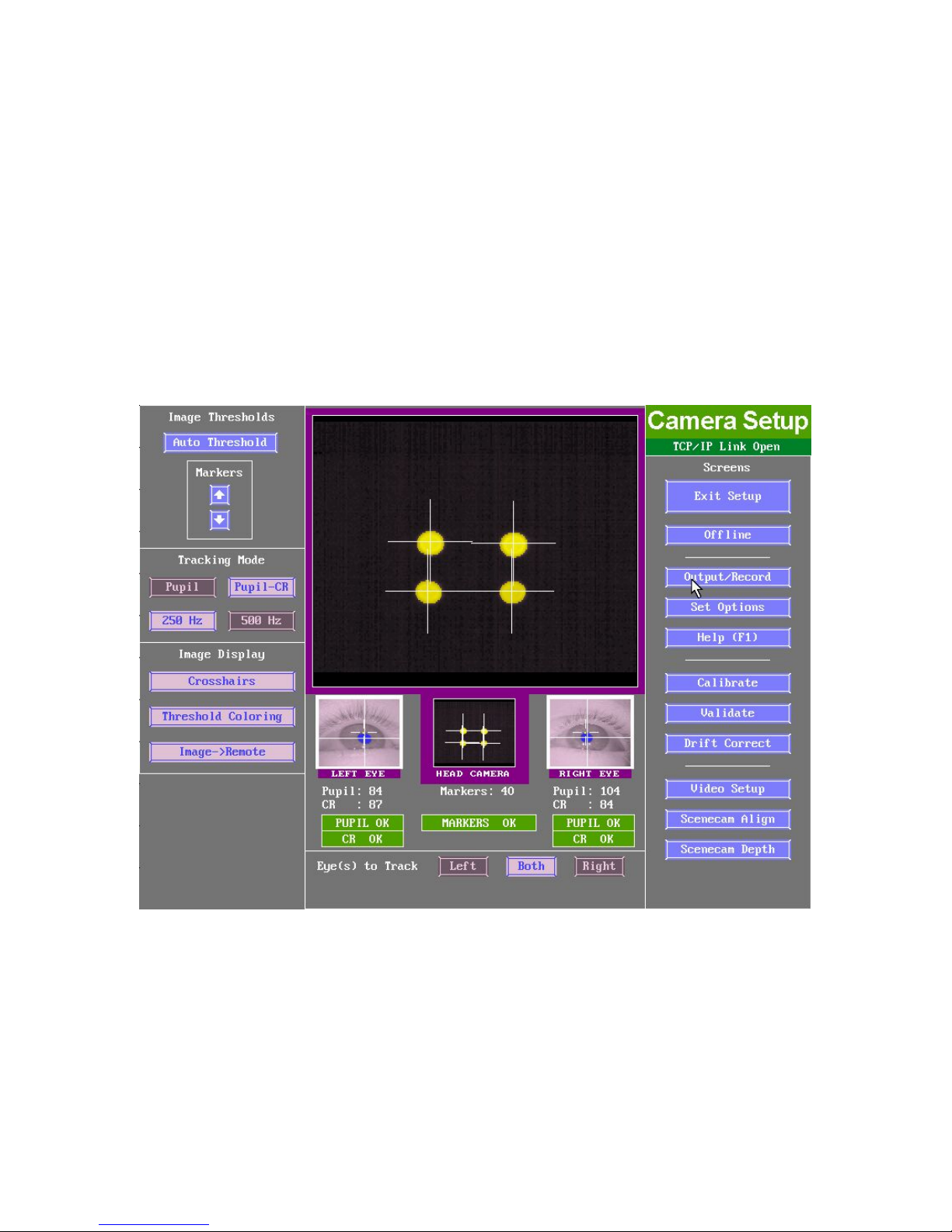
Figure
2-1: EyeLink II Camera Setup Screen
2.1.1 Purpose
This is the central screen for most EyeLink II setup functions. From this screen
(see Figure 2-1) the eye and head tracking cameras can be set up, and their
images can be thresholded. Eye(s) to be tracked, tracking mode and options
can also be set. Calibration, validation, drift correction, and scene camera
EyeLink II Scene Camera User Manual © 2004-2007 SR Research Ltd.
2
Page 8
operations (e.g., video setup, camera alignment, and depth correction) can also
be performed from this screen.
2.1.2 Main Functions
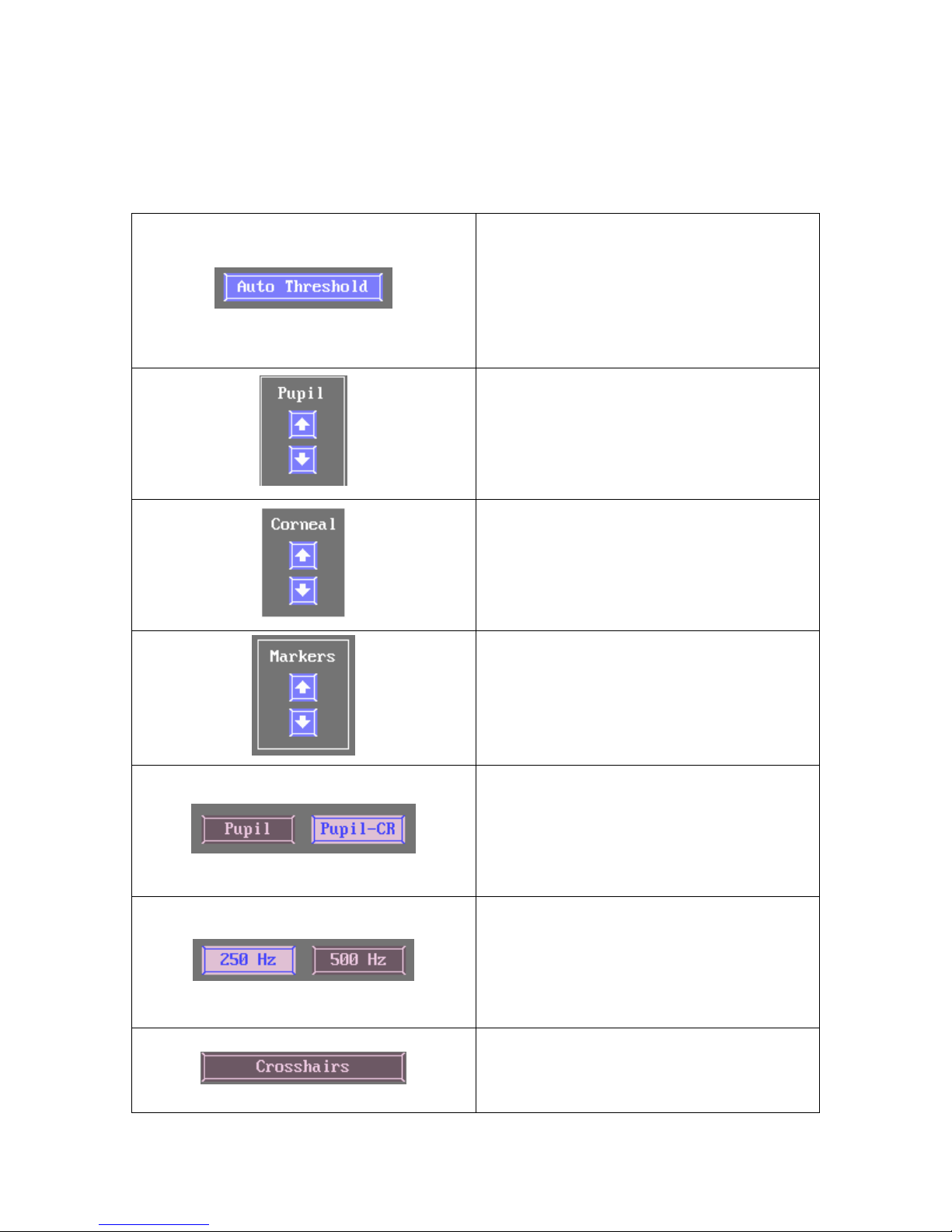
Press Auto Threshold to threshold the
selected camera image. In most cases
auto thresholding will set the correct
image threshold for the camera.
Keys: A = Auto threshold selected
image
Use the arrow buttons to manually
increase or decrease the selected
camera’s pupil threshold.
Keys: ⇑ and ⇓ = increase and decrease
threshold
If available, use the arrow buttons to
manually increase or decrease the
selected camera’s corneal threshold.
Keys: + and - = increase / decrease
corneal reflection threshold
If available, use the arrow buttons to
manually increase or decrease the
head camera threshold.
Keys: ⇑ and ⇓
Select the tracking mode for recording.
Here the Pupil-Corneal Reflection
mode is selected.
Keys: P toggles Pupil only or Pupil-CR
mode selection
Select the sampling rate for recording.
Here 250 Hz is selected. Note that in
Pupil-CR mode, 500Hz is not available.
Keys: F = toggles sampling Frequency
selection
EyeLink II Scene Camera User Manual © 2004-2007 SR Research Ltd.
Toggles display of crosshair in eye
camera images.
Keys: X = toggle crosshair display
3
Page 9
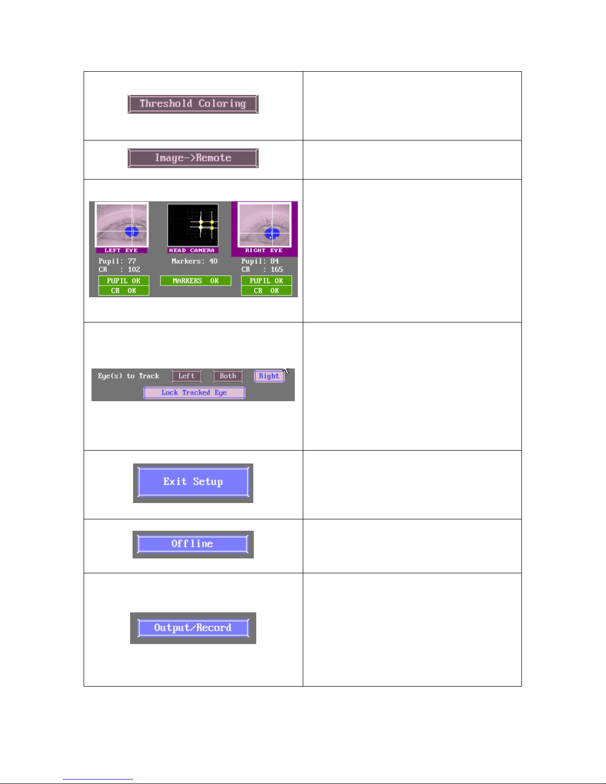
Toggles display of threshold coloring in
eye camera images.
Keys: T = toggle threshold coloring
display
Select to present the camera display
image on the Display Monitor.
To select the camera to display as a
large image click on the desired image
thumbnail. The selected image
thumbnail has a heavy border around
it. Here the Right Eye camera is
selected. Image thresholds and status
are indicated below each thumbnail.
Keys: ⇐ and ⇒ to move left or right
on image row
Select the eye(s) to track during
recording. Here the Right eye is
selected. Press the “Lock Tracked Eye”
button to lock the current selection on
the display PC.
Keys: R = select Right Eye
L = select Left Eye
B = select Both Eyes
Press Exit Setup to go to the screen
that was available prior to accessing
the Camera Setup window.
Keys: ESC = exit camera setup
Press Offline to be returned to the
EyeLink II offline screen.
Keys: ESC = go to Offline screen
Select Output / Record to go to the
output screen, from which you can
start a manual recording session. This
button is usually only accessed when
using the EyeLink II in standalone
mode.
Keys: O = go to Output screen
EyeLink II Scene Camera User Manual © 2004-2007 SR Research Ltd.
4
Page 10
Select Set Options to go to the EyeLink
II options screen, where a variety of
system options and settings can be
configured. Note that any value on this
screen can be programmatically
overridden by the API during
experiment setup.
Keys: S = go to Set options
Press Help (F1) to access the online
help page for Camera Setup. All
available key shortcuts are also listed
on the Help screen.
Keys: F1 = open Help screen
Select Calibration to go to the
Calibration screen. After setting up the
eye cameras and thresholding, you
need to Calibrate the system.
Keys: C = go to Calibrate screen
Select Validation to be taken to the
Validation Screen. Validation allows
you to get a sense of the gaze position
accuracy of your Calibration.
Validation should always be run after
Calibration.
Keys: V = go to Validate screen
Select Drift Correction to go to the
Drift Correction Screen. Drift
Correction can be performed before
and during an experiment; allowing
gaze position to be realigned if
headband slippage or significant pupil
size change has increased gaze
calculation error.
Keys: D = go to Drift correction screen
Perform video overlay or scene camera
setup. This is used to ensure accurate
gaze position mapping onto the overlay
device. If video alignment is not
properly carried out, the accuracy of
EyeLink II Scene Camera User Manual © 2004-2007 SR Research Ltd.
5
Page 11
gaze on overlay will be negatively
influenced.
Keys: W = go to Video Setup screen
Perform alignment between the scene
camera and head camera. This must
be done anytime the relative position
between the scene camera and the
head camera changes.
Keys: Y = go to Scene Camera
Alignment screen
Perform correction to the gaze cursor
drawing in the overlay display to
improve accuracy for recordings that
track eye movements at uncalibrated
depths. Please note it is only possible
to perform depth correction for a
binocular recording.
Keys: Z = go to Scene Camera Depth
Setup screen
2.1.3 Key Shortcuts
Key Function
⇐ and ⇒
R
L
B Select both eyes for recording
P Toggle Pupil only or Pupil-CR mode selection
F Toggle sampling frequency selection
A Auto threshold selected image
X Toggle crosshair display
T Toggle threshold coloring display
⇑ and ⇓
C Go to the Calibration screen
V Go to the Validate screen
D Go to the Drift correction screen
O Go to the Output screen
S Go to Set Options page
F1 Open the Help dialog, in the help screen there is a brief
W Go to the Video Setup screen
Select between left eye camera, head camera and right eye
camera.
Select Right eye for recording
Select left eye for recording
Increase and decrease threshold
overview of the role of this page and the key functions for it
EyeLink II Scene Camera User Manual © 2004-2007 SR Research Ltd.
6
Page 12
Y Go to the Scene Camera Alignment screen
Z Go to the Scene Camera Depth Setup screen
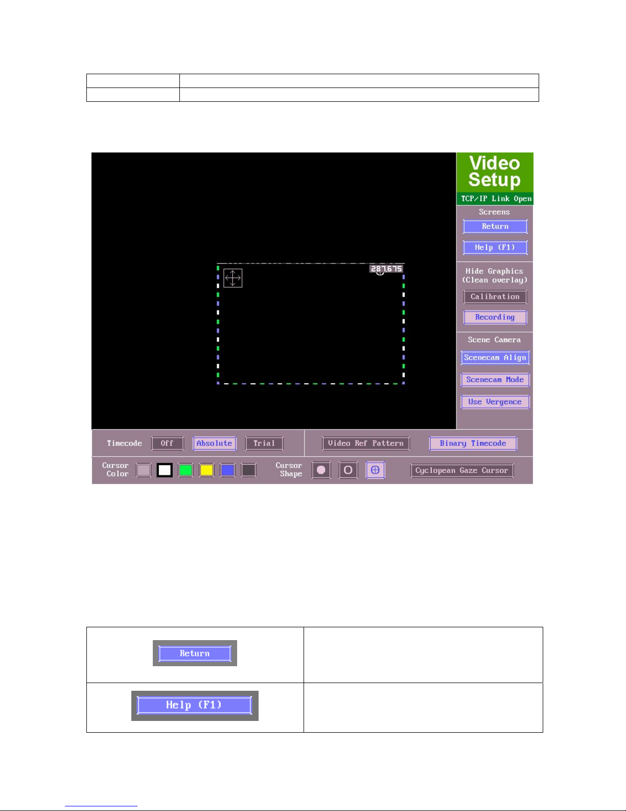
2.2 Video Setup Screen
Figure
2-2: EyeLink II Video Setup Screen
2.2.1 Purpose
This screen (Figure 2-2) is used to perform video overlay or scene camera setup.
This is essential to ensure accurate gaze position mapping onto the scene
camera overlay display.
2.2.2 Main Functions
Press Return to the EyeLink II tracker
EyeLink II Scene Camera User Manual © 2004-2007 SR Research Ltd.
setup screen.
Keys: Enter = return to camera setup
Press Help (F1) to access the online help
page for Camera Setup. All available key
shortcuts are also listed on the Help
7
Page 13
screen.
Keys: F1 = open Help screen
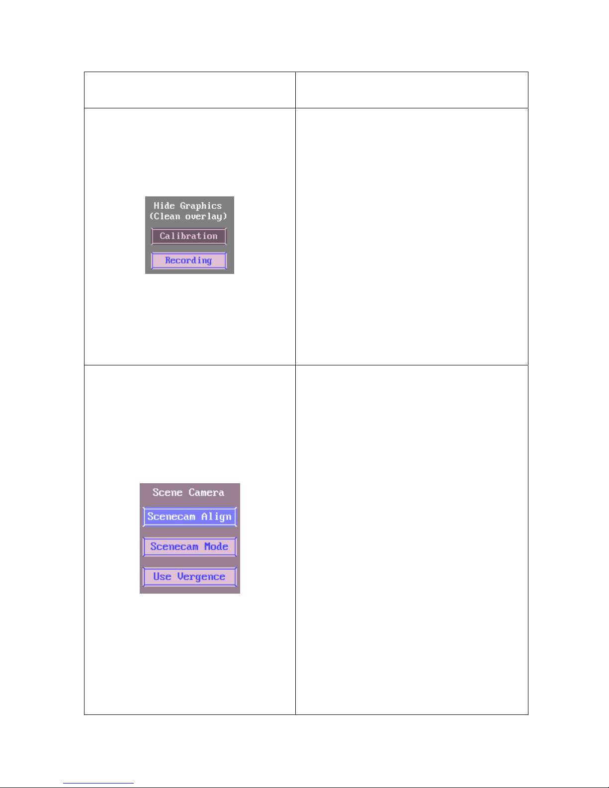
If “Calibration” button is disabled,
additional feedback values are printed
out on the overlay graphics during
validation.
If the “Recording” button is disabled, the
user-drawn graphics can be drawn on
the host PC screen and therefore
displayed behind the gaze cursor during
recording. These graphics may aid
analysis or serve illustrative purposes.
Keys:
X = Toggle feedback/cursors in
calibration/validation screen.
R = No user-drawn graphics in recording
These buttons are related to the scene
camera setup operations.
“Scenecam Align”: Pressing this button
will take the use to the Scene Camera
Alignment Screen (see section 4.3 for
details).
“Scenecam Mode”: If enabled, will apply
adjustments to the gaze cursor position
in the overlay graphics, taking into
consideration the scene camera
alignment settings, as well as the camera
distortion correction. This mode should
be enabled for a recording using the
scene camera for tracking gaze positions
involving different scene depths. With a
recording using the standard overlay
mode, “Scenecam Mode” button should
be disabled – as a result, the “Scenecam
Align” and “Use Vergence” buttons will
also be disabled on the camera setup
screen.
EyeLink II Scene Camera User Manual © 2004-2007 SR Research Ltd.
“Use Vergence”: If enabled, depth
8
Page 14
correction, if available, will be applied to
the gaze positions in the overlay
graphics.
Keys: S = Scene Camera cursor mapping
in recording;
D = Enable/Disable scene camera depth
correction.
Y = Go to the scene camera alignment
screen.
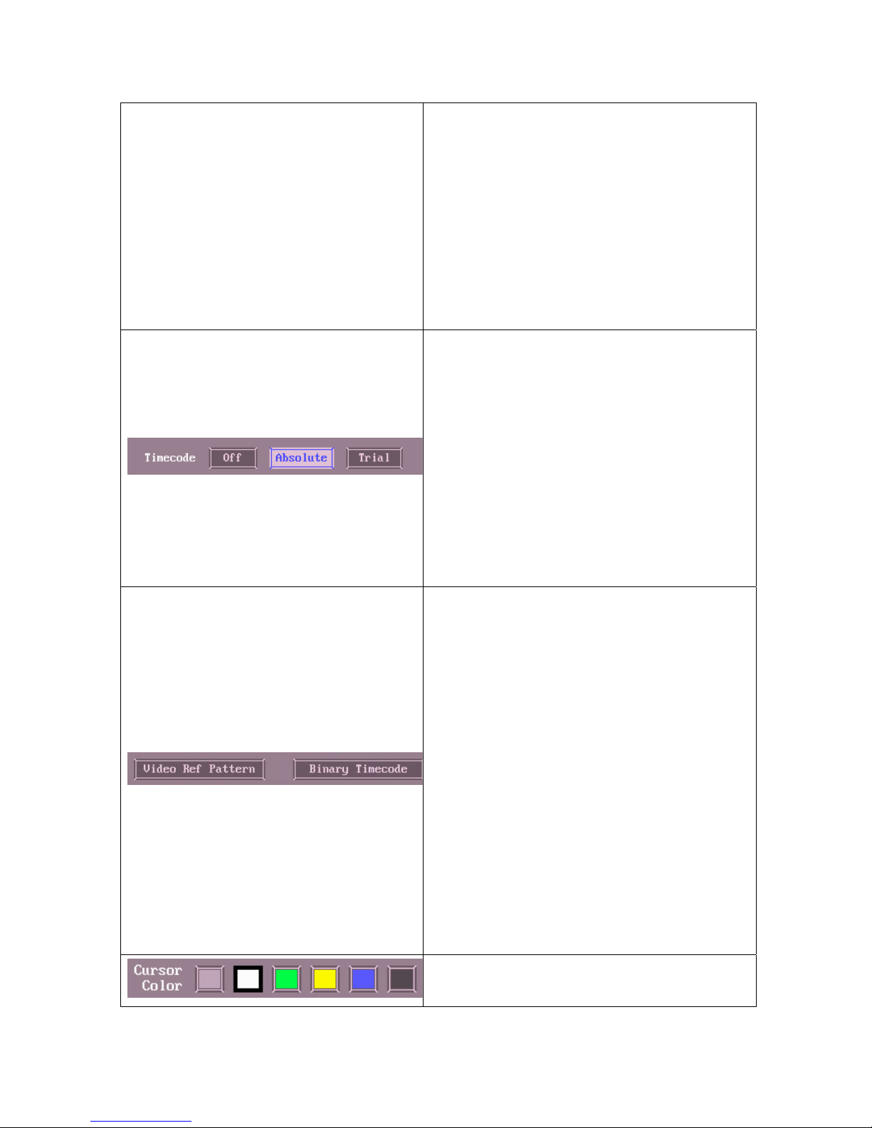
The timecode may be set to “Absolute”,
which displays the actual tracker time in
milliseconds that is used for the
timestamps for samples, events, and
messages recorded in the EDF file or as
real-time link data. If the “Trial” mode is
selected, the timecode displays the
milliseconds elapsed since the start of
the trial. No timecode will be shown if
“Off” is selected.
Keys: T = Select timecode type
“Video Ref Pattern”: Will be used by
future scene camera AVI saving
application to provide proper alignment
between the AVI file and eye tracker
video overlay.
“Binary Timecode”: Turns on/off the
binary timecode, which represents the
machine-readable EDF time. This will be
used in the future AVI saving application
for millisecond-accuracy alignment
between the AVI clip and the EDF timing.
Keys:
V = Show video alignment pattern;
M = Toggle on/off the machine-readable
timecode line
Several cursor colors can be selected
from the Video Setup screen, the most
EyeLink II Scene Camera User Manual © 2004-2007 SR Research Ltd.
9
Page 15
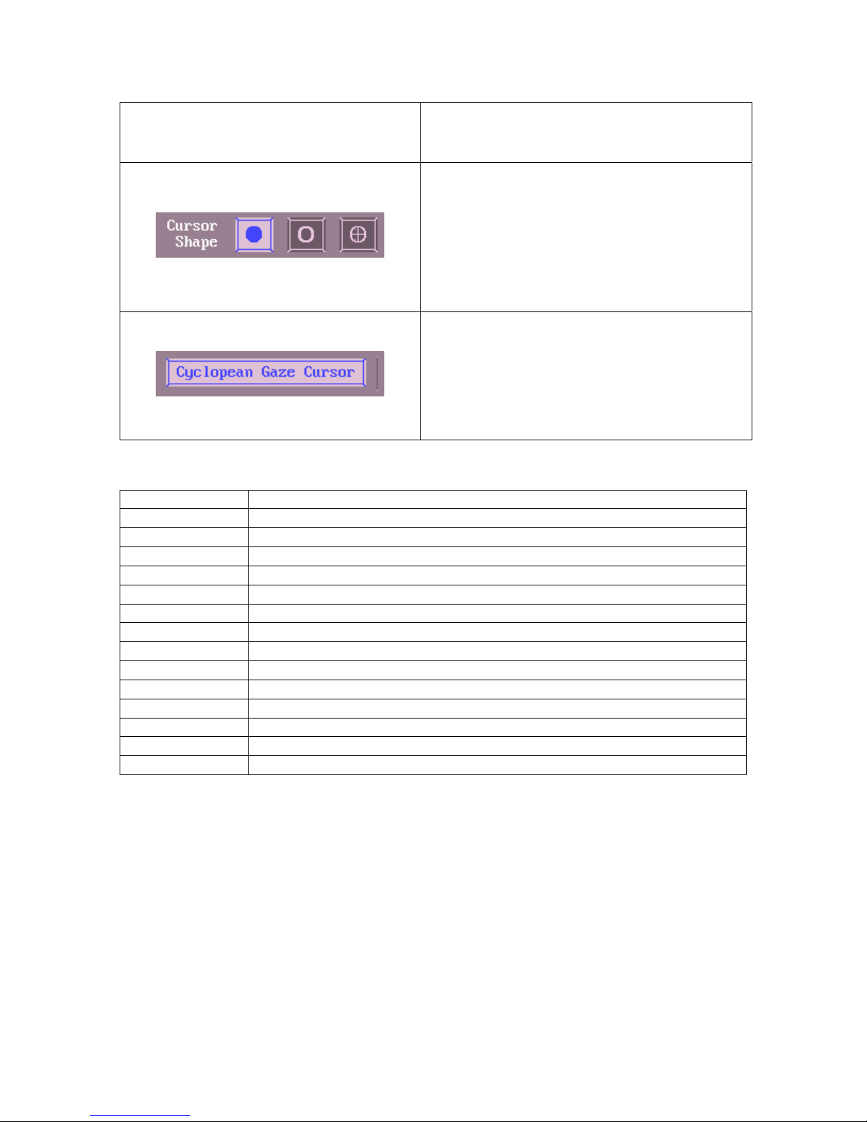
useful of which are yellow and white.
Keys: C = Gaze cursor color.
Gaze cursors for use in the video overlay
have a selectable shape, which may
improve visibility. Cursors may either be
a solid circle, a hollow circle, or a hollow
circle with a cross in the center.
Keys: G = Gaze cursor type
If enabled, draws a single gaze cursor,
representing the average of the two eyes.
If disabled, gaze cursors are drawn
separately for each eye.
Keys: B = Binocular or Cyclopean cursor
2.2.3 Key Shortcuts
Key Function
G Gaze cursor type
C Gaze cursor color
T Timecode type
X No feedback cursors in the calibration/validation screen
R No user-drawn graphics in recording
S Scene Camera cursor mapping in recording
V Show video alignment pattern (setup only)
M Show machine-readable timecode line
B Binocular or Cyclopean gaze cursor
Arrow keys Move the selected corner of the overlay window
Tab Toggle the corner of overlay window to move
F9 Reset overlay window to default position
Enter / ESC Return to Set Options screen
F1 HELP (this screen)
EyeLink II Scene Camera User Manual © 2004-2007 SR Research Ltd.
10
Page 16
2.3 Scene Camera Alignment Screen
Figure
2-3: EyeLink II Scene Camera Alignment Screen
2.3.1 Purpose
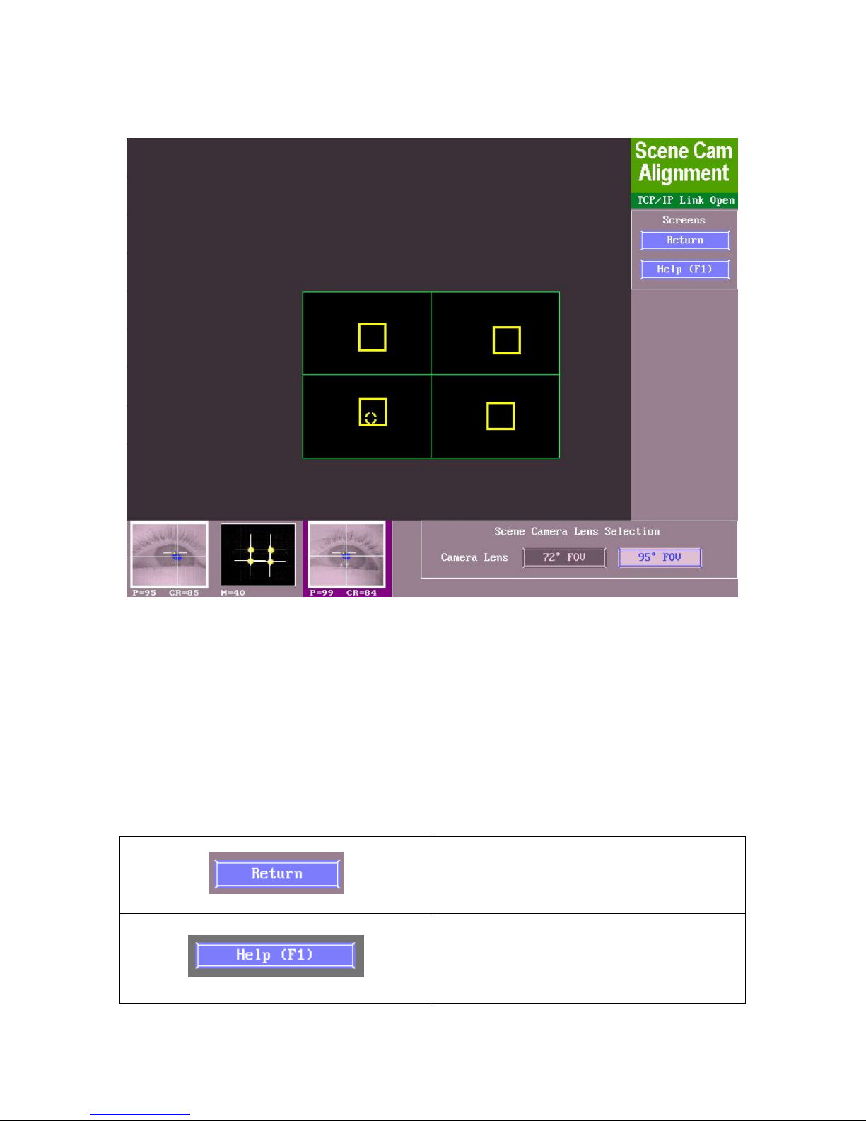
This screen (Figure 2-3) is used to align the scene camera to the head camera.
This is done by selecting the proper lens type, then using the mouse to place
the four boxes around the four IR markers on the calibration monitor. The
alignment should be done anytime the relative position of the scene camera
changes from the head camera (see section 4.3 for details).
2.3.2 Main Functions
Press Return to the EyeLink II tracker
setup screen.
Keys: Enter = return to camera setup
Press Help (F1) to access the online
help page for Camera Setup. All
available key shortcuts are also listed
on the Help screen.
EyeLink II Scene Camera User Manual © 2004-2007 SR Research Ltd.
11
Page 17
Keys: F1 = open Help screen
This allows the user to select the
camera lens type. Make sure this
setting matches exactly with the actual
type of lens installed in the scene
camera.
Keys: L = Select the scene camera lens
type
2.3.3 Key Shortcuts
Key Function
L Select the scene camera lens type;
Enter / ESC Return to Set Options screen
F1 HELP (this screen)
2.4 Scene Camera Depth Setup Screen
EyeLink II Scene Camera User Manual © 2004-2007 SR Research Ltd.
12
Page 18
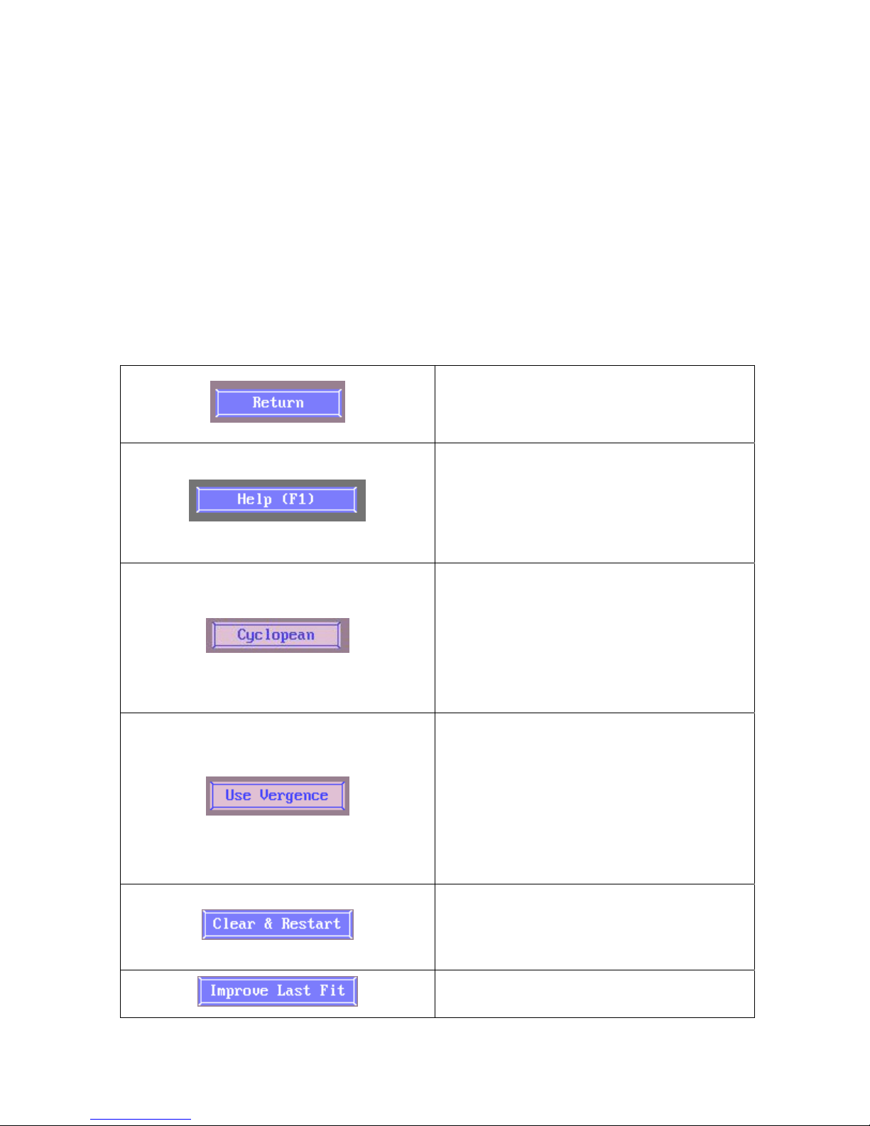
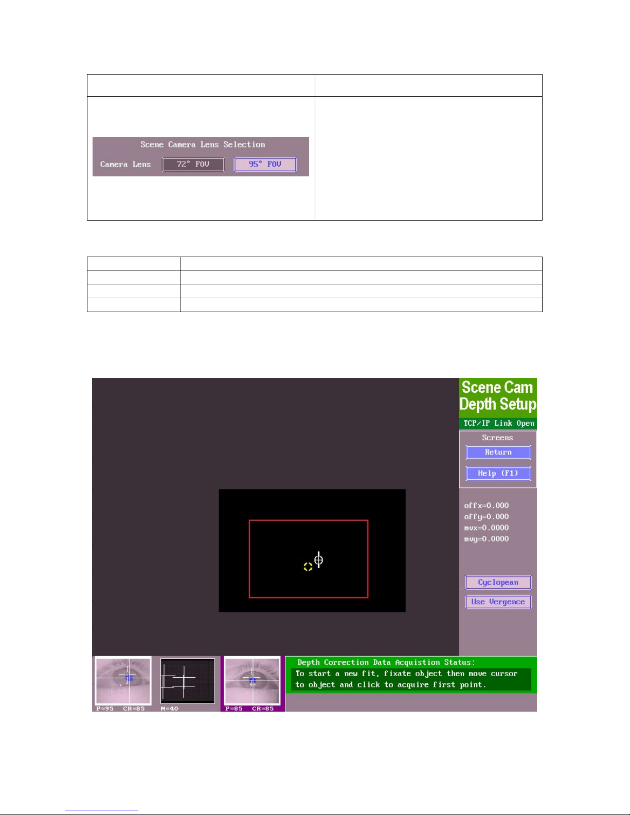
Figure 2-4: EyeLink II Scene Camera Depth Setup
Screen
2.4.1 Purpose
This screen (Figure 2-4) is used to correct for depth parallax (i.e., inaccuracy in
the gaze cursor drawing) in the scene camera overlay caused by the separation
between the participant’s eye and the scene camera. If both eyes are being
tracked, the binocular data can be used to correct at other viewing depths.
This screen allows the experimenter to collect several extra fixations on targets
presented at significantly different depths (see section 4.6 for full details).
2.4.2 Main Functions
Press Return to the EyeLink II tracker
setup screen.
Keys: Enter = return to camera setup
Press Help (F1) to access the online
help page for Camera Setup. All
available key shortcuts are also listed
on the Help screen.
Keys: F1 = open Help screen
If enabled, draws a single gaze cursor,
representing the average of the two
eyes. If disabled, gaze cursors are
drawn separately for each eye.
Keys: B = Binocular or Cyclopean gaze
cursor
If enabled, depth correction, if
available, will be applied to the gaze
positions in the overlay graphics (see
section 4.5 for details).
Keys: D = Enable/Disable vergencebased depth correction for gaze cursor
drawing.
If pressed, this will clear all of the data
points collected for depth adjustment.
Keys: R = Restart collection (clear data).
If pressed, this will keep the existing
data points collected and improve upon
EyeLink II Scene Camera User Manual © 2004-2007 SR Research Ltd.
13
Page 19
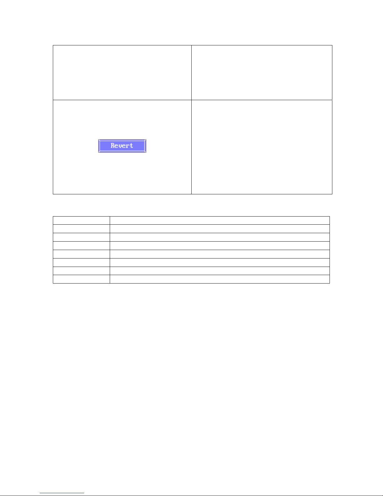
the last fit by adding more data points.
Note that this button will only be
visible following an initial depth
correction.
Keys: I = Improve last fit.
If pressed, this will abandon the newly
collected data points and revert to the
previous parameters. By clicking this
button again, both the previous data
points and the more recent data points
collected will be kept. Note that this
button will only be visible following an
initial depth correction.
Keys: V = Revert to last entry or restart.
2.4.3 Key Shortcuts
Key Function
Enter / ESC Return to Set Options screen
F1 HELP (this screen)
B Binocular / Cyclopean cursors
D Enable/Disable vergence correction
R Restart collection (clear data)
I Improve last fit
V Revert to last entry or restart
EyeLink II Scene Camera User Manual © 2004-2007 SR Research Ltd.
14
Page 20
2.5 Record Screen
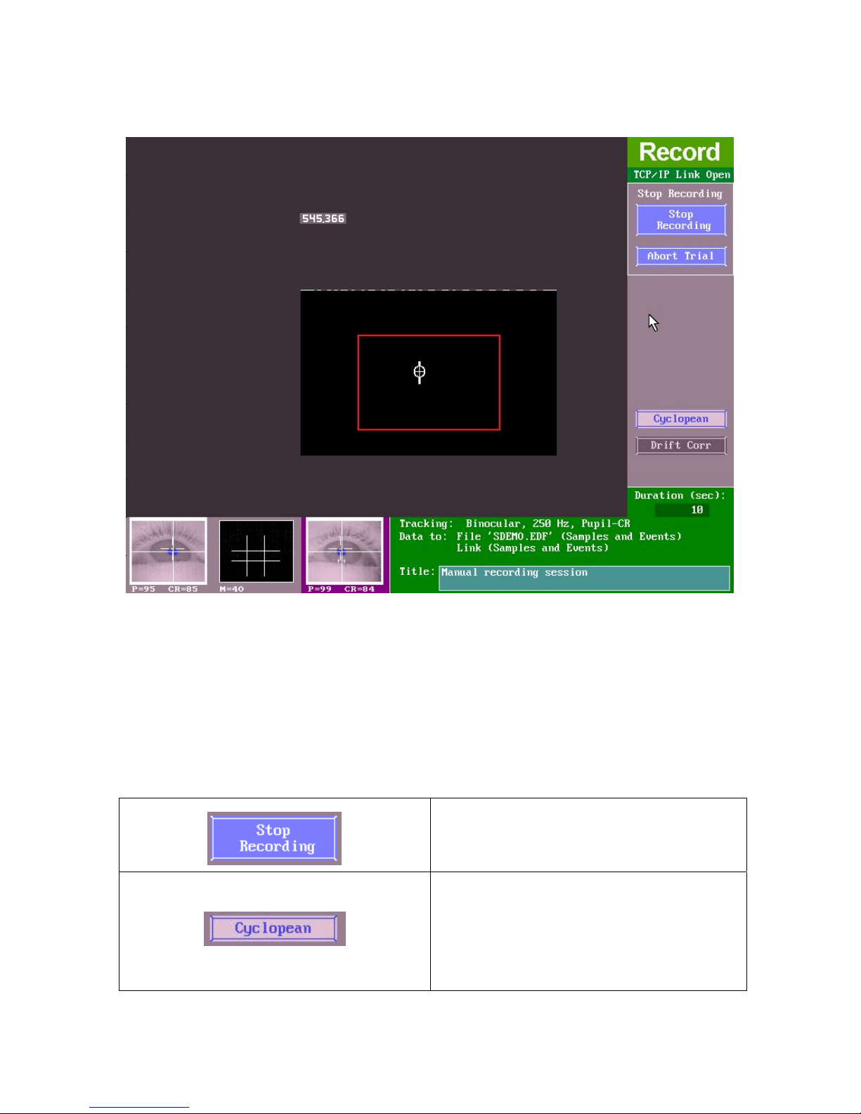
Figure 2-5: EyeLink II Record Screen
2.5.1 Purpose
A menu of options allows opening and closing (EDF) files, setting data to be
recorded, and other output-related options. This mode (see Figure 2-5) always
precedes manual entry into Output mode, to allow parameter preview.
2.5.2 Main Functions
Stops the recording of data to the
EyeLink Data File.
Keys = ESC
If enabled, draws a single gaze cursor,
representing the average of the two
eyes. If disables, gaze cursors are
drawn separately for each eye.
Keys: B = Binocular or Cyclopean gaze
EyeLink II Scene Camera User Manual © 2004-2007 SR Research Ltd.
15
Page 21
cursor
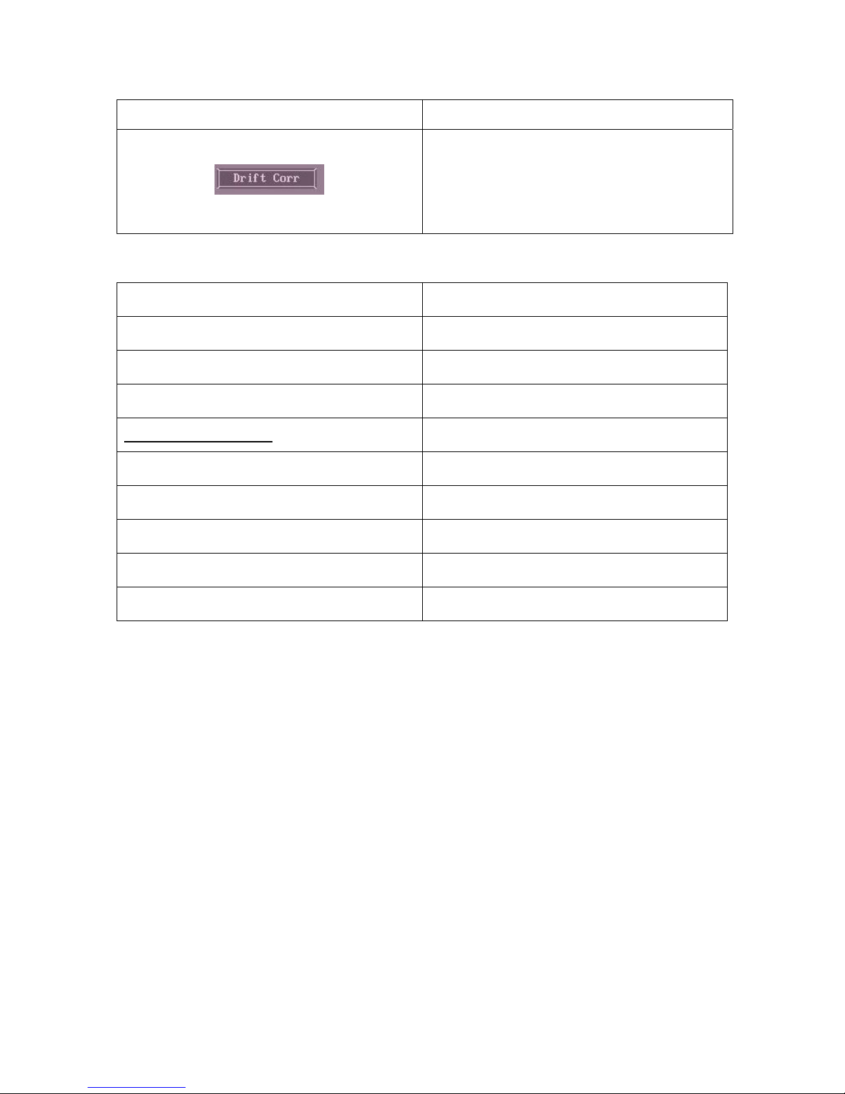
If this button is pressed, an online drift
correction can be performed (see
section 4.8 for full details).
Keys: F = Online offset correction;
2.5.3 Key Shortcuts
ESC Exit to output screen
CTRL + ALT + A Abort trial menu
F Online offset correction
B Cyclopean binocular display
After Trial Aborted
S Setup (Calibrate, camera setup)
R Repeat Trial
N Next Trial
CTRL + ALT + T Terminate Experiment
CTRL + ALT + Q Terminate program
EyeLink II Scene Camera User Manual © 2004-2007 SR Research Ltd.
16
Page 22

3. Setting up and Configuring the SceneLink Application
The current chapter goes through the hardware and software installation before
the scene camera option can be used. It also contains trouble shooting
information on the common problems in using the SceneLink application.
3.1 System Requirements
The following items are required to perform a scene camera EyeLink experiment
with the SceneLink application:
• A VGA overlay device (AVT-3170 Scan Converter, i.e., “Overlay Box”)
supplied by SR Research, including necessary cabling.
• Scene cameras (with cables and power supply) supplied by SR Research.
• An advanced digital video converter (Canopus ADVC 55, 100, or 110),
including the necessary cabling (a IEEE 1394 cable and a S-Video or
composite video cable). Power supply is also supplied for ADVC 100/110
converter and for ADVC 55 converter if a laptop is used as the display
PC. Please note that ADVC 100 or 110 is required for scene camera
recordings with audio.
• A fast display computer (2.0 GHz or faster CPU and at least 512 MB
RAM) with two large hard disks installed. One of the hard disks (120 GB
or more disk space with 7,200rpm) is solely devoted for scene camera
video saving, as we need about 1 Gigabyte of hard disk space for each 5
minutes of video recording. Note that the hard disk must be defragmented and preferably formatted in NTFS file system with the largest
block size.
• The display computer must also have a reasonably good video card
installed with at least 64 Megabyte of video memory. Known supported
video cards include ATI 9500 Radeon and nVidia GeForce4 MX 400.
Known unsupported ones include WildCat high end ones.
• The display PC must has a 6-pin or 4-pin firewire 1394 port (and driver
for it if required).
• If you want to record audio data as well, make sure you have a good
microphone and an amplifier.
3.2 Installing Scene Camera
If the scene camera option is purchased after the base system, follow the
instructions below for installing the scene camera on the headband:
EyeLink II Scene Camera User Manual © 2004-2007 SR Research Ltd.
17
Page 23
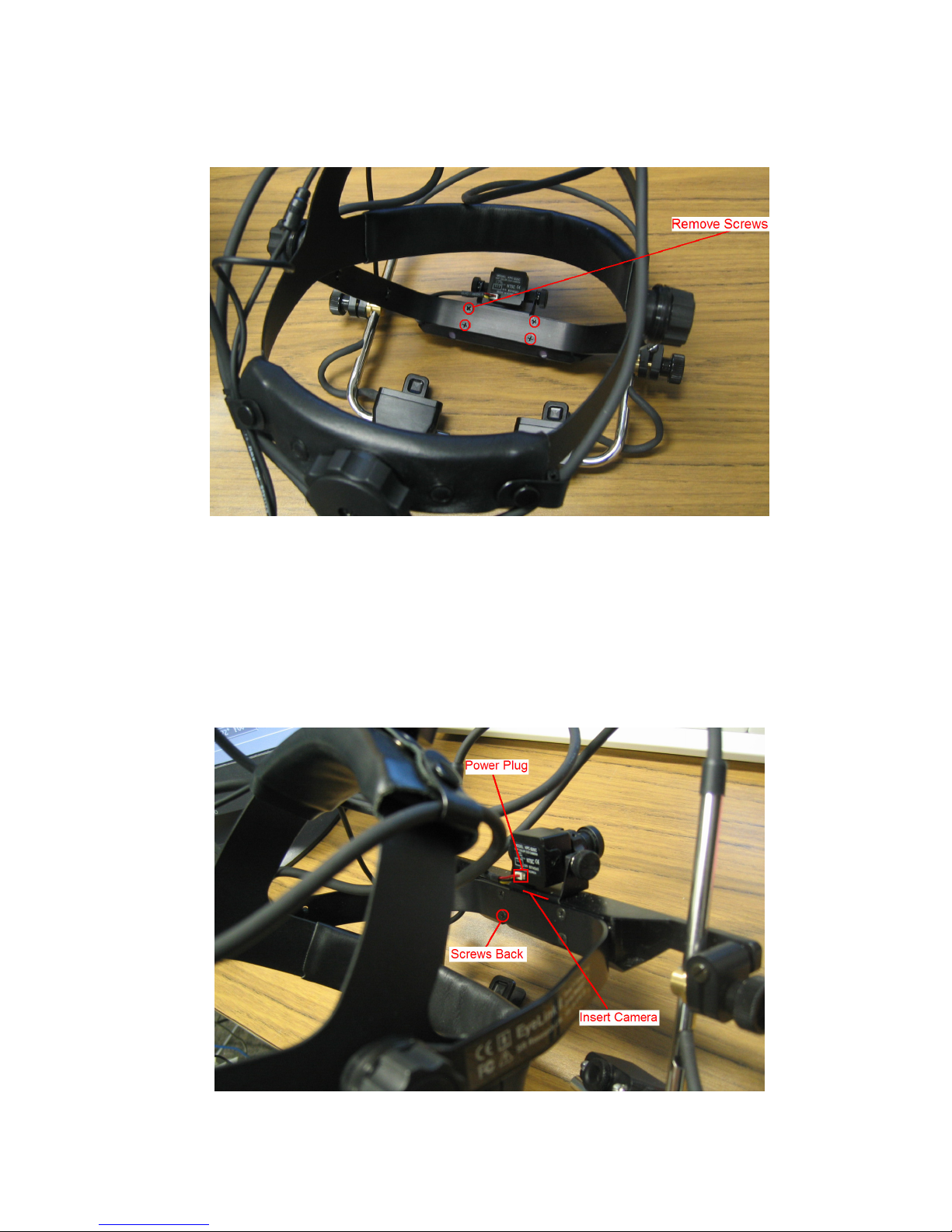
- Use an SR Research supplied screwdriver to remove the four screws on
the head camera bracket (see Figure 3-1).
Figure
3-1: Remove Screws on the Head Camera
Bracket
- Insert the scene camera bracket between the head camera bracket and
the head camera clamp (see Figure 3-2).
- Align the holes on the head camera clamp, scene camera bracket, and
the head camera bracket, and put back the screws. Plug the power
adapter into the scene camera.
EyeLink II Scene Camera User Manual © 2004-2007 SR Research Ltd.
18
Page 24
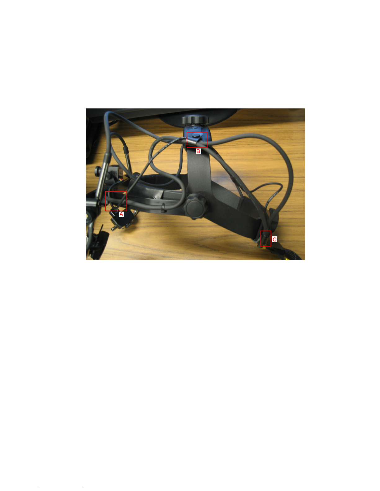
Figure 3-2: Insert Scene Camera between the Head
Camera Clamp and the Head Camera Bracket
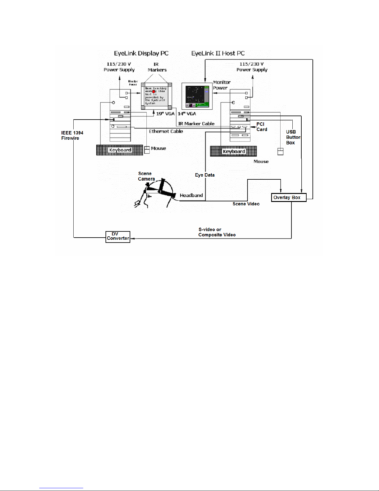
- Dress the cables of the scene camera with buttons on the headband
frames as illustrated in Figure 3-3. Wire the scene camera cable between
the headband frame and head camera cable (see A). Undo buttons B and
C, put the scene camera cable through, and fasten the button back.
Figure
3-3: Dress the Scene Camera Cables
- Loosen the screws of the scene camera and angle the scene camera
appropriately so that it sees as much of the scene of interest as possible,
and then tighten the camera screws.
3.3 Wiring and Configuration
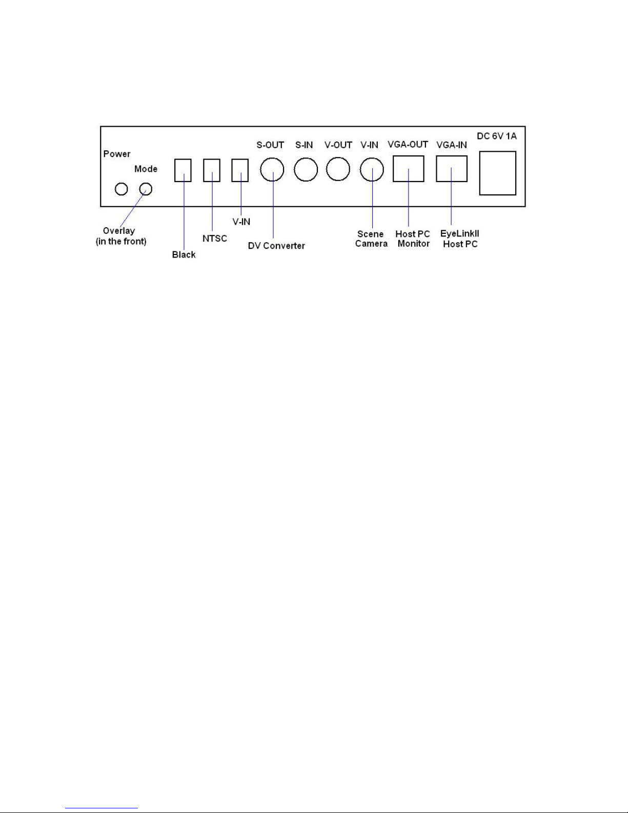
To set up the EyeLink scene camera option, please follow the wiring diagram in
Figure 3-4. The basic cabling steps are:
• Have the EyeLink base system ready. This includes the headband,
marker cables, and ethernet cable setup (see section 2 “Hardware
Installation” of EyeLink ® II Installation Guide).
• Set up the green AVT 3170 Overlay Box, including all cabling and
settings configuration.
• Set up the ADVC Digital Video (DV) converter box.
EyeLink II Scene Camera User Manual © 2004-2007 SR Research Ltd.
19
Page 25
Figure
3-4. EyeLink System Connection in a Scene
Camera Recording
3.3.1 Setting up the Overlay Box
The following steps should be followed to set up the overlay box:
• Connect the “VGA-IN” of the overlay box to the VGA card of the EyeLink
II host computer and “VGA-OUT” to the monitor of the host
• Next, connect the scene camera output to the overlay input and the
overlay output to the Canopus DV converter box with proper cables.
Figure 3-5 illustrates the connection between the RCA plug from the
scene camera and the “V-IN” of the overlay box and the connection
between the “S-OUT” and the S-Video input of the DV Converter.
• Plug in the power adapter of the overlay box.
• For best overlay quality, the following settings may be used:
Overlay (Key) switch: black
TV System: NTSC.
EyeLink II Scene Camera User Manual © 2004-2007 SR Research Ltd.
20
Page 26
Video Input: S-IN (if S-Video In is used for the scene camera input);
or V-IN (if V-In is used.)
Figure
3-5: Wiring Diagram for Scene Camera Option.
3.3.2 Setting up the Digital Video Converter
The following steps should be followed to set up the Digital video (DV) converter
box:
• The “S-OUT” of the AVT-3170 overlay box should be connected to “S
VIDEO IN” on the front of the Canopus ADVC converter box (or the “VOUT” of the overlay box to the “VIDEO IN” of the DV converter if a
composite video cable is used).
• Connect the IEEE 1394 firewire cable between the Canopus ADVC
converter box and the display computer. If you use a laptop as the
display PC, plug the larger 6-pin end into the back of the box and the
smaller 4-pin end into the computer.
• If you are using the ADVC 100 Converter box or you are using a laptop
as display PC, please plug in the AC adapter of the DV converter box. If
you use the ADVC 55 or ADVC 110 Converter box and have a desktop as
the display PC, you may use the 6-pin-to-6-pin 1394 firewire cable
without the optional AC adapter.
DV cable, please make sure the power of both PC and the DV converter, if
used, are off. The DV converter may be damaged because of a power surge.
Note: When you connect or remove the
3.3.3 Recording Audio Data
Version 1.0 of the SceneLink application supports recording of audio data with
an ADVC 100 or 110 converter (ADVC 55 is not supported). To do this, the
user should connect the microphone to an amplifier; the output from the
amplifier should then be connected to the L/R RCA jack at the front (or the
“Audio In” minijack at the back, depending on the cable and converter used). In
addition, the user should check for the settings of the mode switch selectors at
EyeLink II Scene Camera User Manual © 2004-2007 SR Research Ltd.
21
Page 27

the back of the DV converter box. The switch that controls the audio mode
should be set to “On” position (i.e., 32kHz/12-bit 4-channel audio). The switch
that controls the “Locked Audio Mode” should be left in the “OFF” position to
make sure audio stays locked to the video.
3.3.4 Using a Dell D-Series Laptop as Host PC
If you are using a Dell D-series laptop as the host PC on a docking station, you
should also have a computer monitor connected to the docking station. Press
“Fn” + F8 (CRT/LCD) so that you will have computer signal sent to both the
monitor and overlay box.
3.4 Software Installation
Both the host PC and display PC need to be configured for use with the EyeLink
II SceneLink application.
3.4.1 Host PC
Copy the existing EyeLink2 directory on the host PC to a new folder as a
backup. Then copy the supplied files into the EyeLink2 folder (tracker version
2.0 or later). These should overwrite the eyelink2.ini and the eyelink2.exe files,
and add a number of extra files (final.ini, scenecam.ini, and vidovl.ini). The
vidovl.ini and scenecam.ini contain all of the settings for using the video overlay
option and scene camera option respectively. If changes to these default
settings are required, please copy and paste the commands to the final.ini and
make the modification in that file for the ease of future maintenance. Users
may also want to do a complete update of the host directory by backing up the
existing directory and then using the latest version downloadable from
(https://www.sr-support.com/forums/showthread.php?t=11).
3.4.2 Display PC
To use the SceneLink application, the display PC must be running on a 32-bit
version of Windows XP (service pack 2 recommended).
• Check whether DirectX version 9.0c is installed on your computer. To
check out the version of DirectX installed, from the DOS prompt type
“dxdiag” or search for the “dxdiag.exe” file in the {windows}\system32
directory and click on it. This will bring up a “DirectX Diagnostic Tool”
dialog box (see Figure 3-6). If an older version of DirectX was installed
on your computer, the user should download the latest version from
http://www.microsoft.com/windows/directx/default.mspx.
EyeLink II Scene Camera User Manual © 2004-2007 SR Research Ltd.
22
Page 28
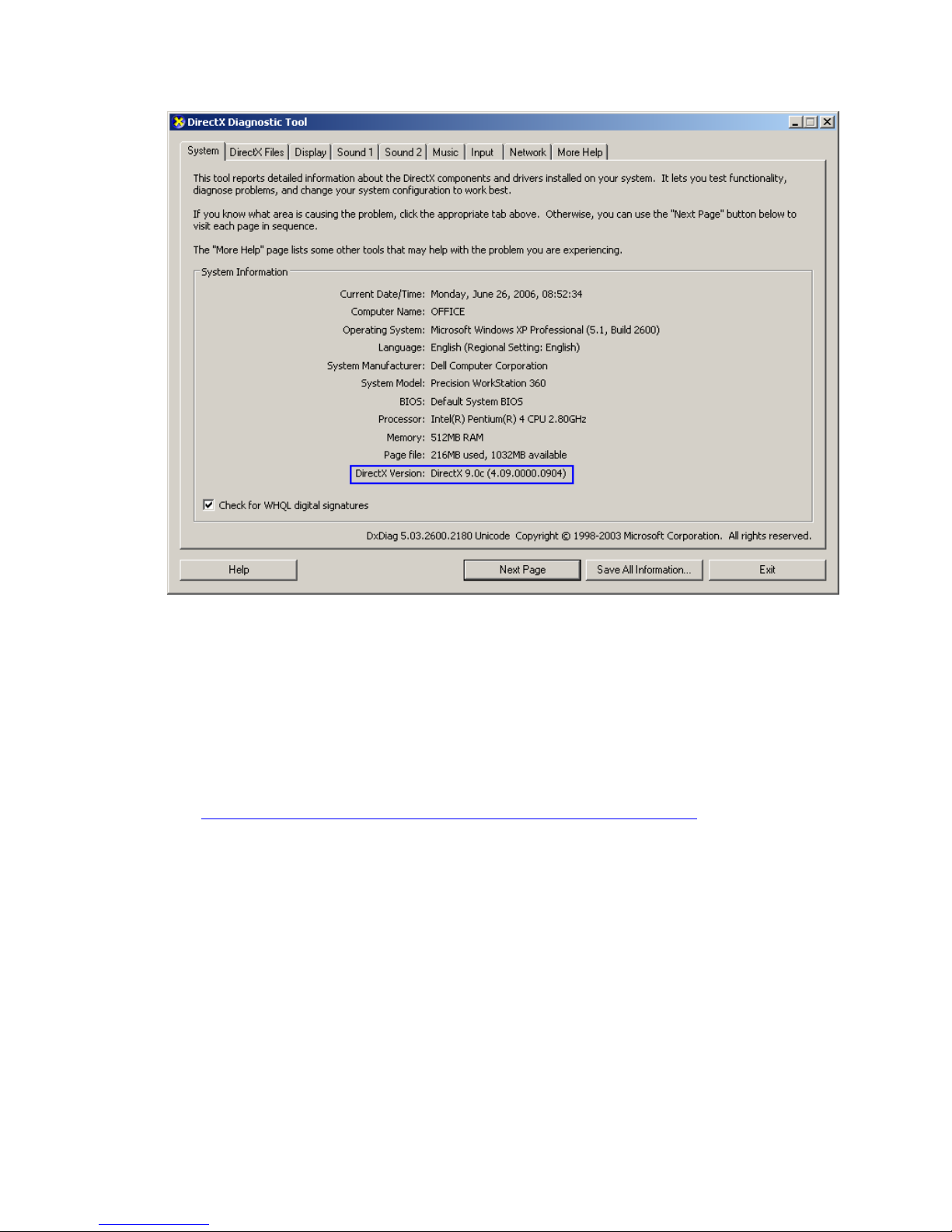
Figure
3-6. Version of DirectX Installed on the Display
PC
• The DriverLinx parallel port driver (Port95NT.exe) should be installed if
the user wants to send or receive synchronization signals through the
parallel port of the display computer. The installer can be found at
“C:\Program Files\SR Research\EyeLink\bin” folder if you have installed
the Windows Display Software
(
https://www.sr-support.com/forums/showthread.php?t=6).
• Run the “scenelink.exe” installer supplied by SR Research Ltd with
default configurations.
3.5 Checking Firewire Connection
Start the EyeLink II Tracker application on the host computer. Run the
SceneLink application from “Start → Programs → SR Research EyeLink →
Scene Camera” of the display PC. The scene camera application should start
up. If you see the following warning information (see Figure 3-7), please check:
EyeLink II Scene Camera User Manual © 2004-2007 SR Research Ltd.
23
Page 29

Figure
3-7. Error in Detecting the DV Connection
• Has a connection been made between the S-Video or composite video
output of the overlay box and the input (on the front) of the Canopus DV
converter box?
• Has the Canopus DV converter box been connected to the display PC
with a firewire cable? If you connect the converter and a laptop with a 6pin-to-4-pin1394 cable, has the optional AC adapter been used?
• If the error information persists, please check the Device Manager of the
display computer to see whether the 1394 firewire is properly configured.
If you are using Windows XP, the quickest check is to use Windows
Movie Maker (from Start -> Programs -> Accessories -> Entertainment) to
see whether you can get video captures from the firewire (if you are
seeing black video, please read section 3.7.3).
If you decide to go ahead without fixing the above DV connection issue, the “File
→ Open Record Session” menu of the application will be disabled. This means
that the scene camera application can be used to play back previous recordings
but not perform new recordings.
3.6 Configuring SceneLink Options
If this is the first time you have run the scene camera application, please check
the application settings before performing a recording. Click on “View ->
Preferences”. In the “General” tab of the following dialog (see Figure 3-8), you
will find an edit dialog for “Capture Location”. This is the location where the
EyeLink data (.EDF) file and scene camera video (.AVI) files are saved. The
default directory setting is “{Window_drive}\Documents and Settings\{User
Name}\My Documents”. Users may want to create a new directory and set the
capture location to that directory.
Please also check the tracker address settings in case your host PC is running
at a different IP address. This is set to “100.1.1.1” by default. The “ADVC
Status” field is used as a diagnostic to show the current connection and playing
status of the DV converter box. If multiple audio cards installed on the display
PC, the “Audio Output” setting allows the user to choose the correct audio
device for audio data playback.
EyeLink II Scene Camera User Manual © 2004-2007 SR Research Ltd.
24
Page 30
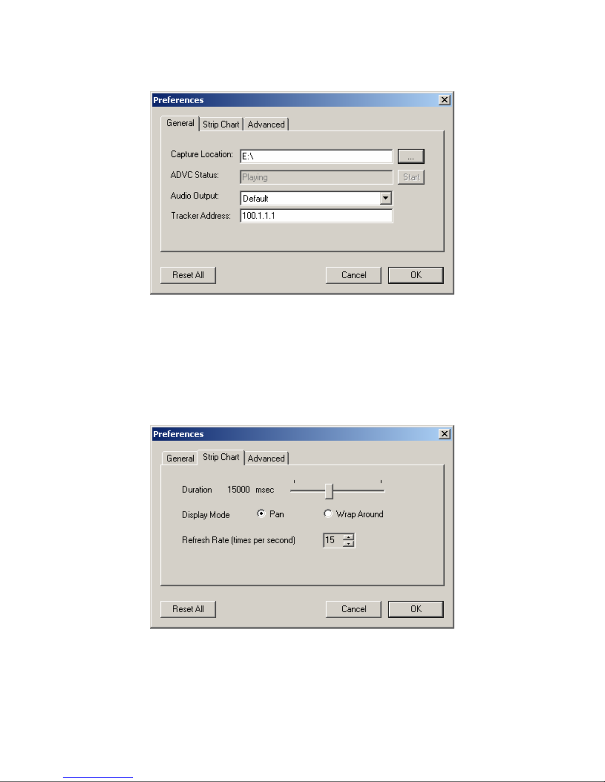
Figure
3-8. General Tab of the Preferences Dialog Box
The “Strip Chart” tab of the preferences dialog box (see Figure 3-9) contains
settings for the strip chart display, which plots the X and Y gaze position as a
function of the current tracker time (see section 4.11). The duration of the gaze
history (5-30 seconds) can be adjusted from the slider bar control. The
frequency of data updating (Refresh Rate in times per second), and display
mode (panning or wrapping around) can also be adjusted.
Figure
3-9. Strip Chart Tab of the Preferences Dialog
Box
The SceneLink software can send out TTL signals to a third-party acquisition
device/computer for synchronization purposes (see section “4.8.2
EyeLink II Scene Camera User Manual © 2004-2007 SR Research Ltd.
25
Page 31
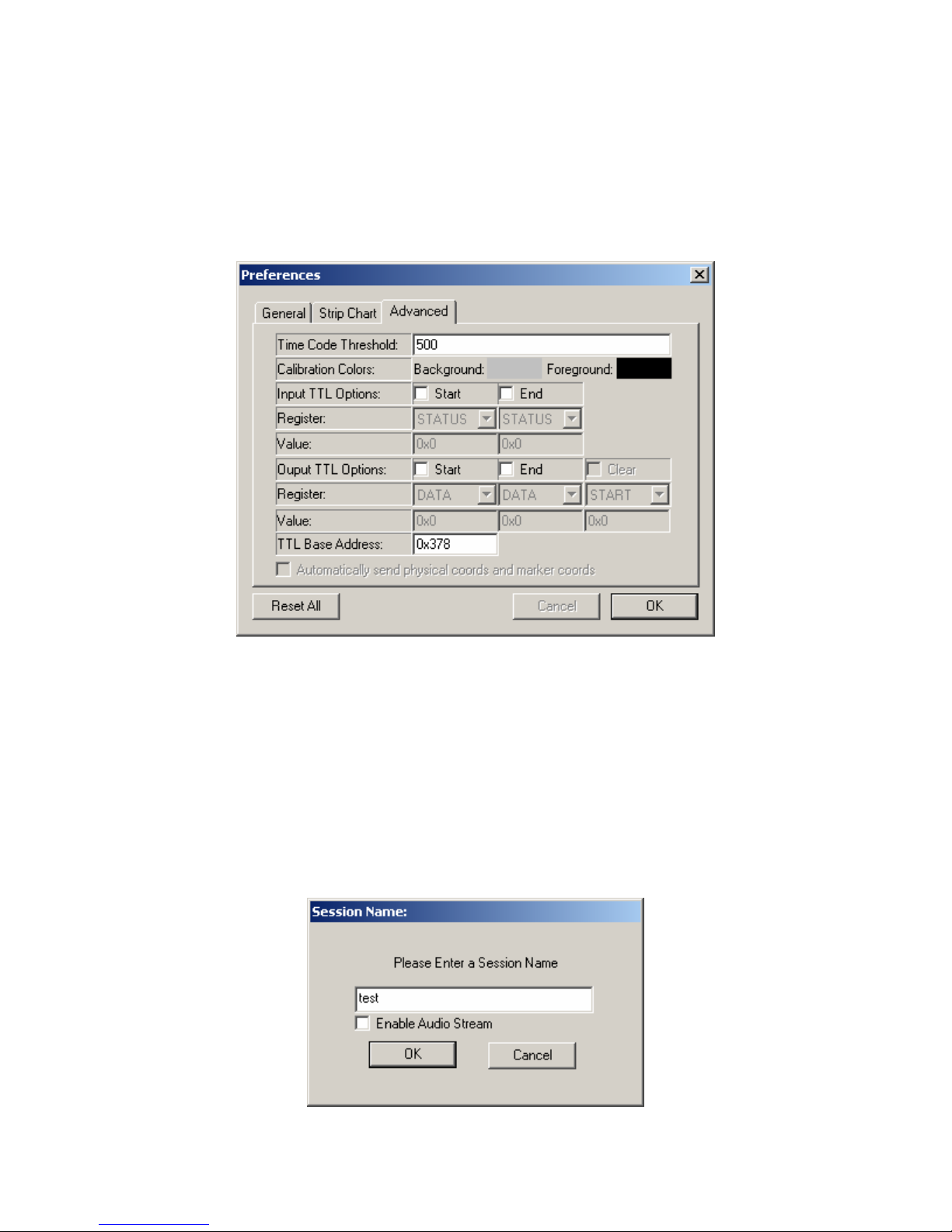
Synchronization with Third-Party Recording Devices”). The software can also
receive incoming signals to control the start and end of scene camera
recordings. The address of the port, register and value of the incoming and
outgoing TTL signals can be configured in the “Advanced” tab of the preferences
dialog box (see Figure 3-10). In addition, the user can set the foreground and
background colors of the calibration screen.
Figure
3-10. Advanced Tab of the Preferences Dialog
Box
3.7 Checking SceneLink Connections and Settings
Start the EyeLink application on the host PC. Click on “Set Options” menu.
Make sure “Enable Overlay” button is enabled. Next, click on “Video Setup”
button. Make sure both “Scenecam Mode” and “Use Vergence” buttons are
enabled. Press button 5 of the overlay remote control to set the overlay box to
2× zoom.
EyeLink II Scene Camera User Manual © 2004-2007 SR Research Ltd.
26
Page 32
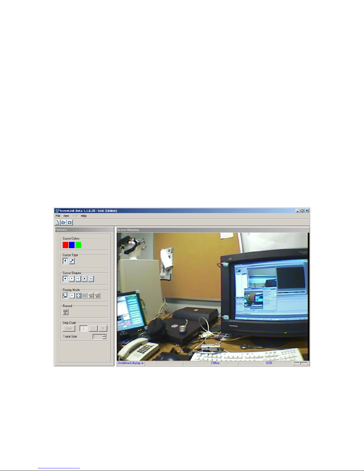
Figure 3-11. Openning a Recording Session.
Click on “File → Open Record Session” to start a scene camera recording
session. (If this menu option is disabled, please see section 3.5 “Checking
Firewire Connection”.) This will bring a dialog box, prompting for a recording
session name (see Figure 3-11). The recording session name should contain no
more than eight ASCII characters (no space or special characters allowed).
Enter the filename and press “OK” button. If you want to record audio data as
well, make sure the “Enable Audio Stream” box is checked. To get better
quality, you may turn the audio volume down while recording so that the high
frequency noise does not occur or you do not hear an echo. You may turn the
volume up when playing back the recording session.
If you see a “connection timed out” or “EyeLink Not Initialized” error message,
please make sure the EyeLink II program is running on the host PC. If
necessary, also check your network settings and the ethernet cable connection
between the host and display PCs. If everything runs fine, the video from the
scene camera should now be displayed on the main window of the SceneLink
application (see Figure 3-12).
Figure
3-12. Initial View of the SceneLink Application
The following sections illustrate initial screens the user may see if the scene
camera option is not properly set up:
• Seeing tracker graphics (section 3.7.1)
EyeLink II Scene Camera User Manual © 2004-2007 SR Research Ltd.
27
Page 33
• Seeing a gray screen (section 3.7.2)
• Seeing a blank screen (section 3.7.3)
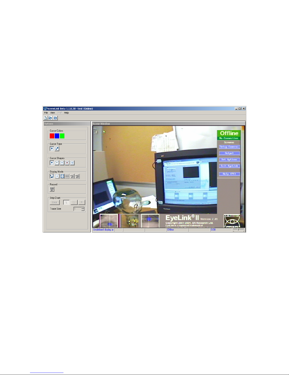
3.7.1 Seeing Tracker Graphics
In the video window of the SceneLink application, if you see scene camera video
with graphics from the tracker program overlaid on the right and bottom edges
(see Figure 3-13), it is likely that the graphics from the tracker screen is not
zoomed. Press button 5 of the overlay remote control to set the overlay box to
2× zoom.
Figure
3-13. Unzoomed Tracker Graphics
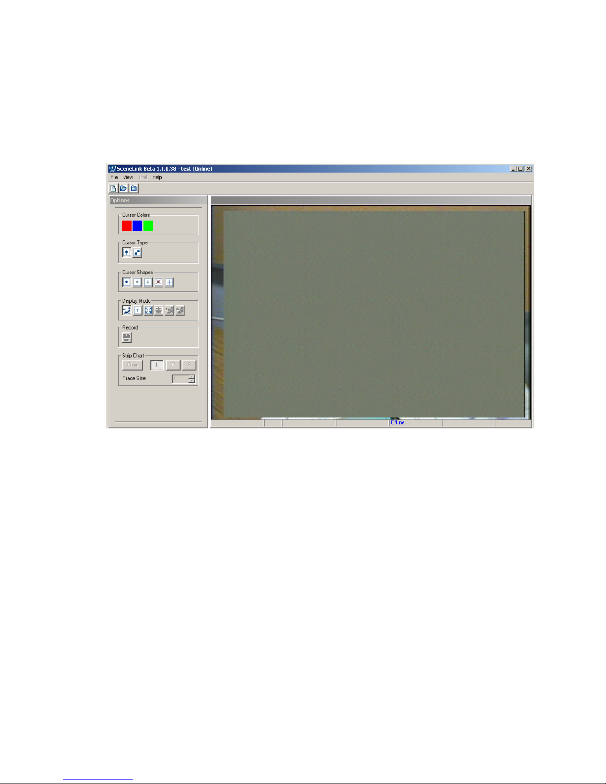
3.7.2 Seeing a Gray Screen
If you see a gray screen with part of video visible at the four edges of the video
window (see Figure 3-14) and you don’t find “Video Setup”, “Scenecam Align”,
and “Scenecam Depth” buttons on the Camera Setup screen of the host
application (see Figure 3-15), please check the following settings:
• Go to the Set Options screen of the EyeLink II Tracker application. Make
sure the “Enable Overlay” button is selected. Click on the “Overlay
Setup” button. In the following video setup screen, make sure the
“Scenecam Mode” and “Use Vergence” buttons are enabled.
• If you don’t see the “Enable Overlay” button at the bottom right corner of
the Set Options screen, quit the EyeLink host application. Do a search
EyeLink II Scene Camera User Manual © 2004-2007 SR Research Ltd.
28
Page 34
on the eyelink2\exe directory for the “vidovl.ini” and “scenecam.ini” files.
Make sure both files are present. Also, open eyelink2.ini to make sure
the following two lines are included in the file.
include "vidovl.ini" // vidovl settings
include "scenecam.ini" // scene camera setting
Figure
3-14. Gray Background Over Video, Check
EyeLink2 Settings
EyeLink II Scene Camera User Manual © 2004-2007 SR Research Ltd.
29
Page 35
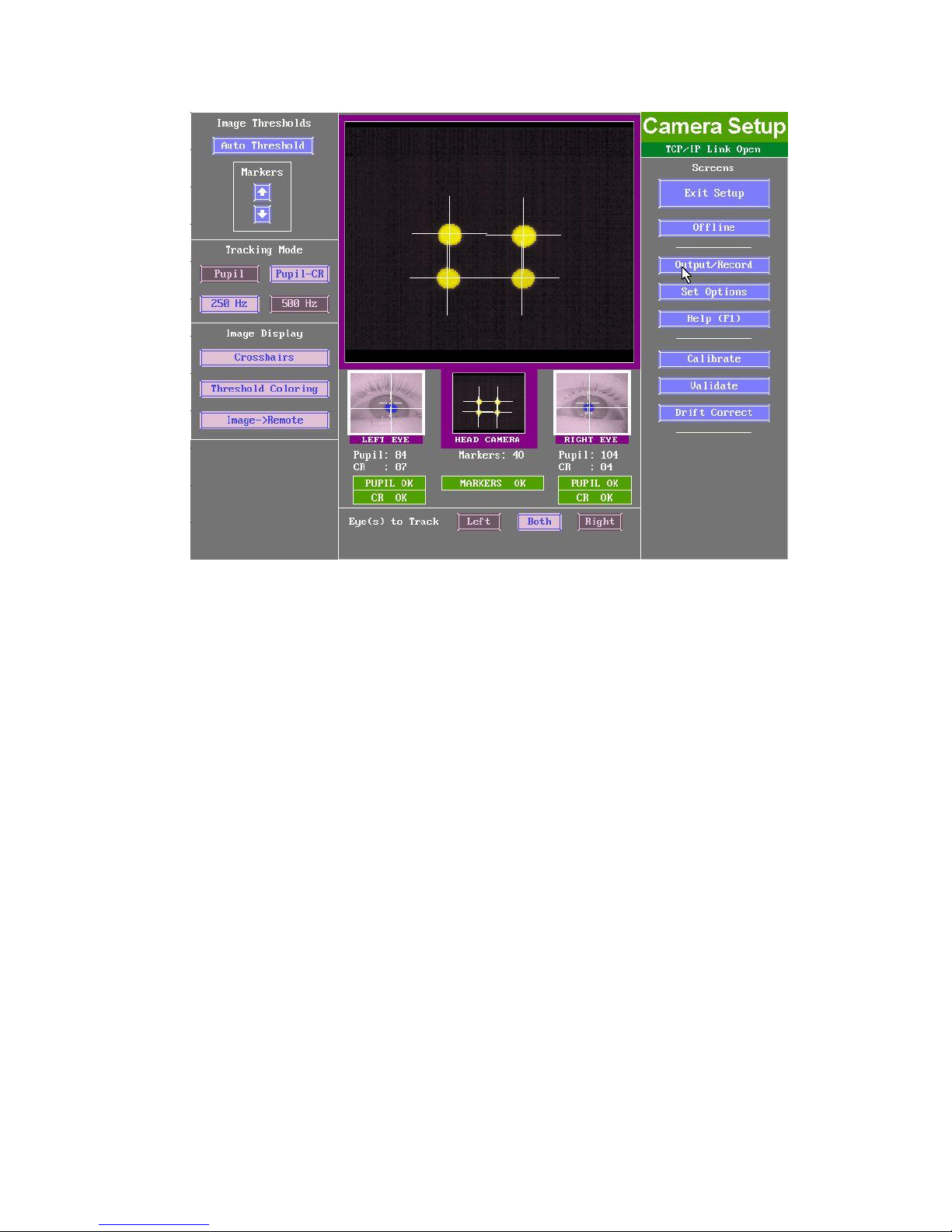
Figure
3-15. Missing Scene Camera Buttons
• If there is no problem with the above two steps, open the Scenecam.ini
and/or final.ini to make sure both
‘scene_camera_gazemap’ are set to “ON” or “YES”.
‘scene_camera_enabled’ and
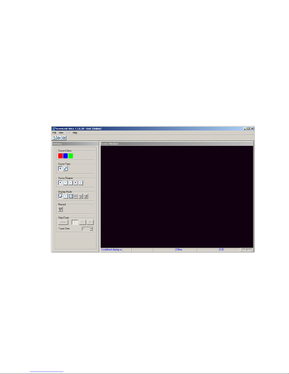
3.7.3 Seeing a Black Screen
If you only see a black screen in the video window (See Figure 3-16), please
check the scene camera system setup again:
• Has the cap of the scene camera been removed?
• Have you plugged in the right power adapter of the scene camera?
• Have you connected the video cable from the scene camera to the “V-IN”
of the overlay box?
• Have you plugged in the right power adapter of the green AVT Overlay
Box? Is it powered on (not in the “standby” mode)?
• Check the follow connections and settings on the AVT Overlay Box:
1) Does the type of scene camera video output cable match the
setting of video source input in the overlay box (i.e., “S-IN” when
S-video input is used and “V-IN” when composite video input is
used)?
EyeLink II Scene Camera User Manual © 2004-2007 SR Research Ltd.
30
Page 36
2) Is the Overlay Box set at “Overlay” mode?
3) Is there any loose connection among the connectors? Try to
disconnect the cables and then re-connect them.
4) If you are using ADVC-100 or 110 converter, the blue light
indicator on the front will be set at “Digital In” mode by default.
Press the silver input select button to switch video input mode to
“Analog In”.
• If you are using ADVC-55 DV converter, do you see the green light on?
The converter has difficulty in detecting the video source if the red light
is on. Check for the possibility of having loose connections.
Figure
3-16. Blank Screen in the Video Window
EyeLink II Scene Camera User Manual © 2004-2007 SR Research Ltd.
31
Page 37
4. Performing Recording with the SceneLink Application
In addition to the usual steps for EyeLink recordings, using the scene camera
option requires extra steps to perform scene camera alignment and depth
correction. In a recording session, the user should perform the experiment
setup in the following order:
- Check the display area setting (i.e., calibrate the size of overlay graphics
display and to align it with the scene camera video).
- Perform (or check) scene camera and head camera alignment
- Do eye/head cameras setup
- Calibration and validation
- Perform depth correction
- Recording and, if necessary, drift correction
The current chapter explains how to perform each of the above steps with the
SceneLink application. The SceneLink application allows for greater flexibility
in scene camera data recording and playback. With this application, the user
has a real-time gaze overlay preview during recording and can change the gaze
cursor and shape on the fly. More importantly, this application allows for scene
camera video saved as digital video (in .AVI file format) without any gaze overlay
graphics. Overlay graphics are generated during data playback.
4.1 Modes of Operation
Recording eye movement data and scene camera video with the SceneLink
application should be controlled from the display PC. Although recordings can be
started and stopped from the host PC, doing this may cause difficulties in data
playback later on.
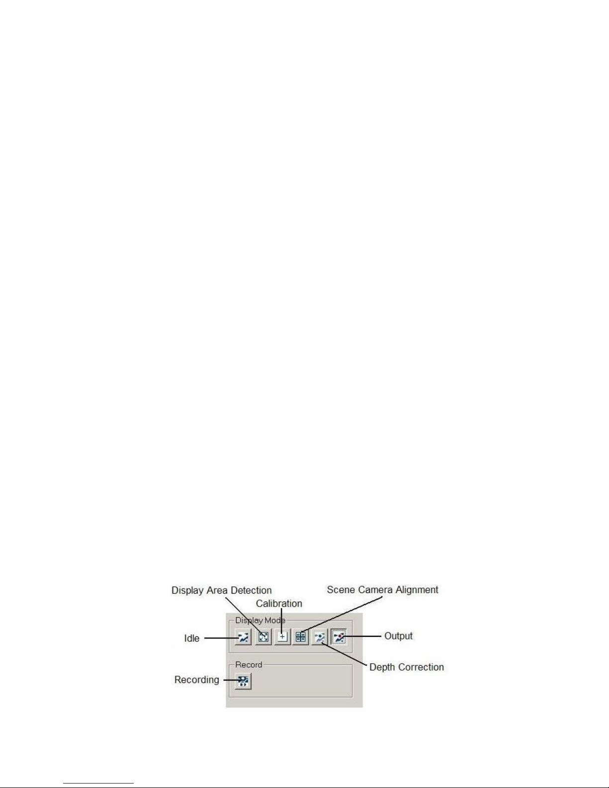
user will have to go through several modes, in the order of display area
checkup, camera setup and calibration, scene camera alignment, depth
correction, output and recording. Each of the above modes is entered by
clicking on the corresponding display mode button (see Figure 4-1).
To perform a recording with the SceneLink application, the
EyeLink II Scene Camera User Manual © 2004-2007 SR Research Ltd.
32
Page 38

Figure 4-1. Modes of Operation for SceneLink
Recording
4.2 Idle (Preview) Mode
The idle mode ( ), the default mode of the SceneLink application, displays the
camera scene on the display computer. This mode is useful for checking the
connection between the host and display PCs and the overlay settings (see
section3.7 “Checking Connections and Settings”). Important! If you see any
menu items of the EyeLink host PC screen shown in the video, please make
sure Button 5 of the overlay remote control has been pressed to zoom in the
host PC video output (see Figure 4-2).
Figure
4-2. Example of Unzoomed Host Screen Overlay
4.3 Display Area Detection Mode
The display area detection mode ( ) is used to calibrate the size of overlay
graphics display and to align it with the scene camera video. When this mode
is entered, some line drawings are added to the scene camera video and a
“Video Alignment” dialog box is displayed (see Figure 4-3), followed by a “Detect
EyeLink II Scene Camera User Manual © 2004-2007 SR Research Ltd.
33
Page 39
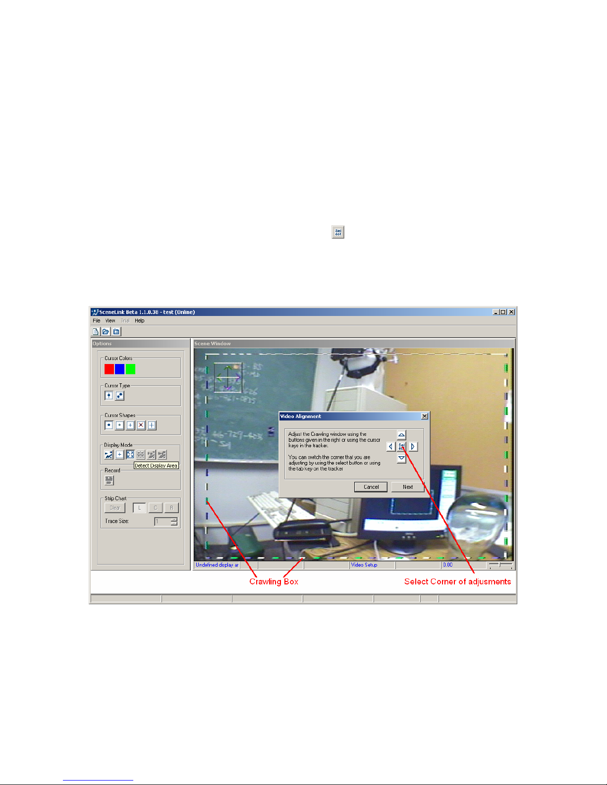
Display Area” dialog box. If you are using a Dell C- or D-series laptop as the
host PC on a docking station, make sure you have computer signal sent to both
the monitor and overlay box (As mentioned earlier, Dell D-series laptop users
should have an extra computer monitor connected to the docking station). If
you do not see a box consisting of a highly visible moving pattern (“crawling
box”) on the SceneLink video screen, you should press “Fn” + F8 (CRT/LCD)
shortcut keys on the laptop keyboard.
In the Video Alignment screen, the user should first adjust the size of the
overlay display, which is indicated by the crawling box. Note also the drawing
of a square with arrows, located just inside the top-left or bottom-right corner of
the crawling box. Click the “select” button (
) on the dialog box to select the
corner of adjustment. Use the four arrows buttons to adjust the size of the
crawling box to maximum while keeping the outside edge of the moving pattern
still fully visible. Click the “select” button to switch to adjusting the other
corner. Press the “Next” button to continue.
Figure
4-3. Adjusting the Size of Overlay Display
Following this, the overlay graphics and scene camera video can be aligned. A
“Detect Display Area” dialog box will appear on the background of gray box with
a white box in it (see Figure 4-4). If the gray box does not appear, please check
the “Video Setup” screen of the host PC to make sure the “Video Ref Pattern”
EyeLink II Scene Camera User Manual © 2004-2007 SR Research Ltd.
34
Page 40
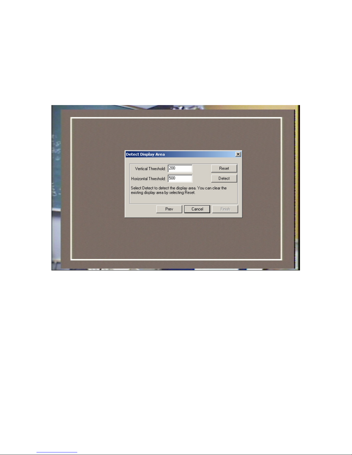
button is enabled. In the “Detect Display Area” dialog box, press the “Detect”
button to let the video card detect the display area (the gray box). If the
detection is successful, two red/pink reference boxes are added onto the display
and the detected area is reported in a message similar to “Detect OK. Display
at 24 8 698 465” (see Figure 4-5). Press the “Reset” button to clear the current
settings and redo display area detection or press the “Finish” button to exit this
mode.
Figure
4-4. Beginning Display Area Detection
In the “Detect Display Area” dialog box, if the red reference boxes do not appear,
the user may need to adjust the values of the “Vertical” and “Horizontal”
brightness threshold downwards by 10%, and then click on the “Detect” button
again. Repeat this step until the reference pattern appears on the screen.
Please make sure the gray background is displayed all the time; otherwise,
please check for the “Video Ref Pattern” button setting on the host PC. The
default threshold settings work for most of recent video cards. If not, please
first check whether you have zoomed in the host PC video output by pressing
button 5 of the overlay box remote control (note the size of the gray box relative
to the “Detect Display Area” dialog box). However, if the reference pattern is not
displayed even when the vertical and horizontal thresholds are adjusted close to
0, please contact SR Research Ltd.
EyeLink II Scene Camera User Manual © 2004-2007 SR Research Ltd.
35
Page 41
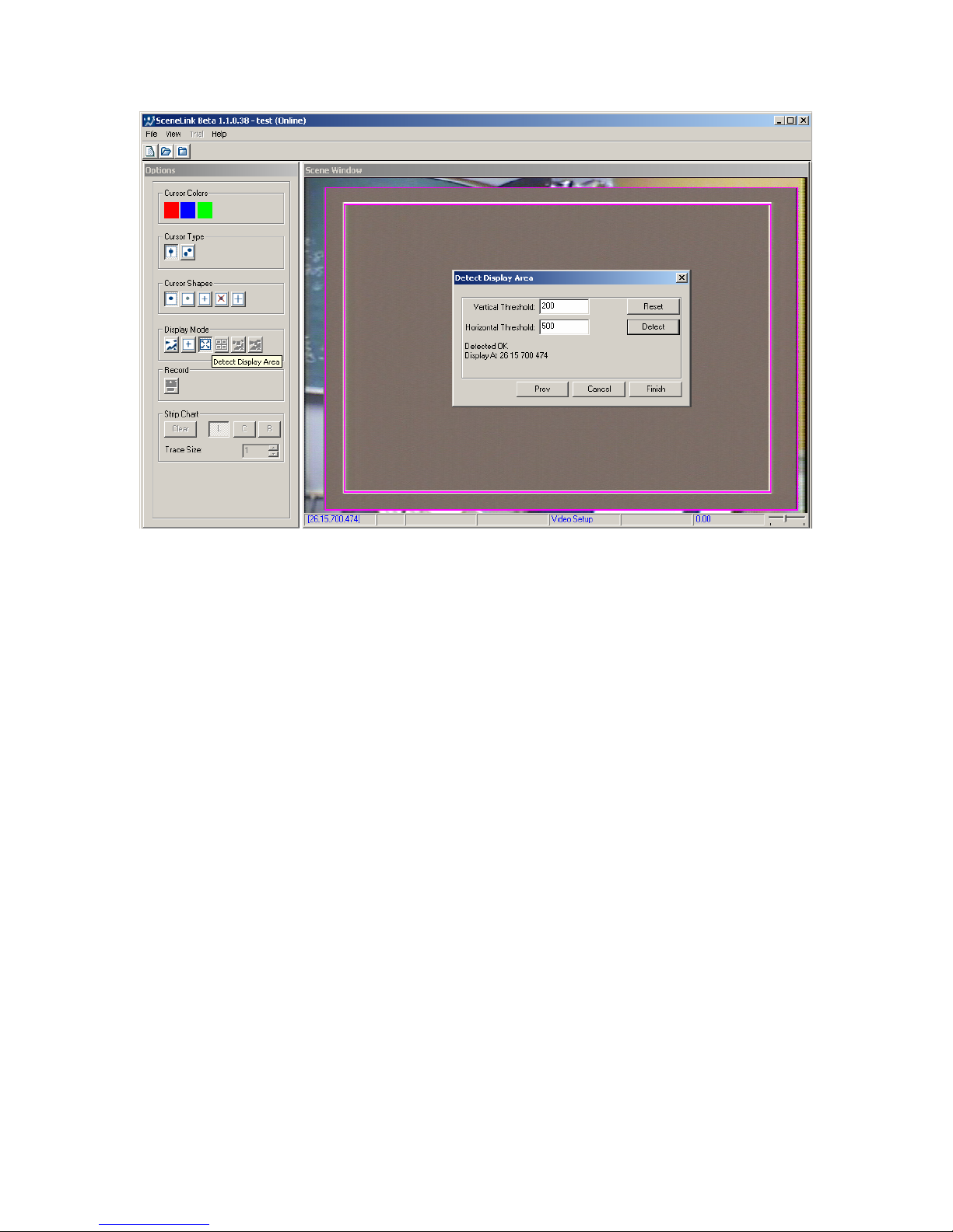
Figure
4-5. Successful Display Area Detection
The SceneLink application is now ready to use. Note that the calibration of
overlay graphics display to scene camera video needs to be done only once, as
long as the overlay and scene camera settings have not been changed.
However, the user should enter this mode to verify this at the beginning of each
recording session.
4.4 Scene Camera Alignment Mode
The optical alignment between the scene camera and head camera must be
done when the scene camera is used for the first time. By performing the
alignment, the gaze accuracy on the overlay display at the calibrated depth is
ensured. To perform the alignment:
- From the Camera Setup Screen of the host PC, press the “Set Options”
button. In the following screen, make sure “Head Tracking” button is
enabled. Press the ENTER key to return to the previous screen.
- On the Scene Camera Alignment screen of the host PC, first check for the
scene camera lens selection. Make sure this setting (72º or 95º field of
view) matches exactly with the actual type of lens mounted on the scene
camera bracket. Note: A 95º lens has a diameter of 17.0 mm measured
from the left end to right end (including the black edge); 13.5 mm
measured from the inner ring (glass part only). A 72º lens has a
EyeLink II Scene Camera User Manual © 2004-2007 SR Research Ltd.
36
Page 42

diameter of 13.5 mm measured from the left end to right end (including
the black edge); 11.2 mm measured from the inner ring (glass part only).
- Click on the “Scene Camera Alignment Mode” button (
) on the display
PC or the “Alignment” button on the Camera Setup Screen of the host
PC.
- Have a participant sit in front of the display PC monitor with IR markers
properly positioned. Place the headband on the participant’s head.
- If necessary, loosen the screws of the scene camera, angle the scene
camera appropriately so that it sees as much of the scene of interest as
possible if the participant looks at the target area/depth. Tighten the
camera screws.
- Ask the participant to fixate at the center of the display PC monitor.
Head movements may be required to ensure that there is only one
marker in each quadrant of the overlay display (separated by colored
lines) and that each marker is reasonably distant from other markers
(see Figure 4-6). Avoid having the markers showing up too close to the
corner of the overlay display as the optical lens distortion is less well
compensated there.
- For each quadrant of the overlay display, place the display PC mouse
cursor over the center of IR marker in the scene video. Click the left
mouse button. This must be done carefully to achieve best accuracy.
- If working properly, the color boxes in the overlay display will move
according to the participant’s head movements. If head tracking is
enabled, the boxes should be always on top of the center of the markers
The scene camera alignment should be done only if the relative position
between the scene camera and the head camera is changed or if the lastrun.ini
file in the eyelink2\exe directory is modified. However, it is a good practice to
check the alignment at the beginning of each recording session.
EyeLink II Scene Camera User Manual © 2004-2007 SR Research Ltd.
37
Page 43
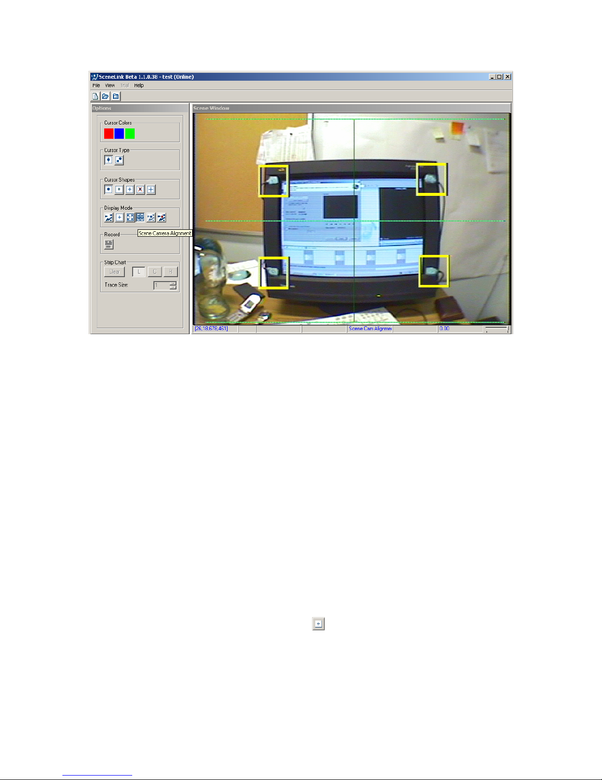
Figure
4-6: Optical Alignment between the Scene
Camera and Head Camera.
4.5 Calibration Mode
For best scene camera performance, recordings must be done in the corneal
reflection mode with both eyes tracked. The corneal reflection mode is used for
the headband slippage protection whereas the binocular tracking is used for
parallax fixup at the non-calibrated depths. In addition, the calibrated region
should be where most of the recording activities happen. If you are performing
a binocular recording, participants should be calibrated in a standard vertical
display to minimize nonlinearity in the calibration mapping. The depth
correction can then be performed on several depth levels in the target space
(e.g., by fixating at several points on a desk). If a recording must be done in a
monocular mode for some reason, try to perform the calibration and validation
as close to the target plane as possible. This is because depth correction is not
possible in a monocular recording and therefore the user must be aware of the
ramifications of doing this (i.e., gaze inaccuracy at uncalibrated planes).
Click on the calibration mode button (
participant in a binocular tracking mode with Corneal Reflection on. Following
the camera setup, perform a calibration by typing ‘C’ on either the host or
display PC keyboard. Note that several types of calibration algorithms have
been provided by SR Research Ltd. If a large calibration region is involved in an
experiment, the “HV13” calibration type (selected from the “Set Options” screen)
EyeLink II Scene Camera User Manual © 2004-2007 SR Research Ltd.
) on the display PC to set up a
38
Page 44
should be used for best calibration accuracy. By default, a nine-point
calibration type (“HV9”) is used for a calibration in which the participant’s eyes
are at a distance from the monitor of about twice the width of the display area
of the Display monitor. If the calibration result is good, proceed with validation
by clicking on the “validation” button or by typing ‘V’ and press the space bar to
initiate the process. After accepting the validation results, the user should
press the “ESC” key on the display keyboard to exit calibration mode. (Do not
use “Alt” + “Tab” key combinations as you are still running the SceneLink
application!!!)
4.5.1 Calibration Colors
The colors of the calibration target and background can be configured through
preferences prior to starting a recording session. Click “View -> Preferences”
from the application menu bar. Select the “Advanced” tab and set the intended
background and foreground/target colors.
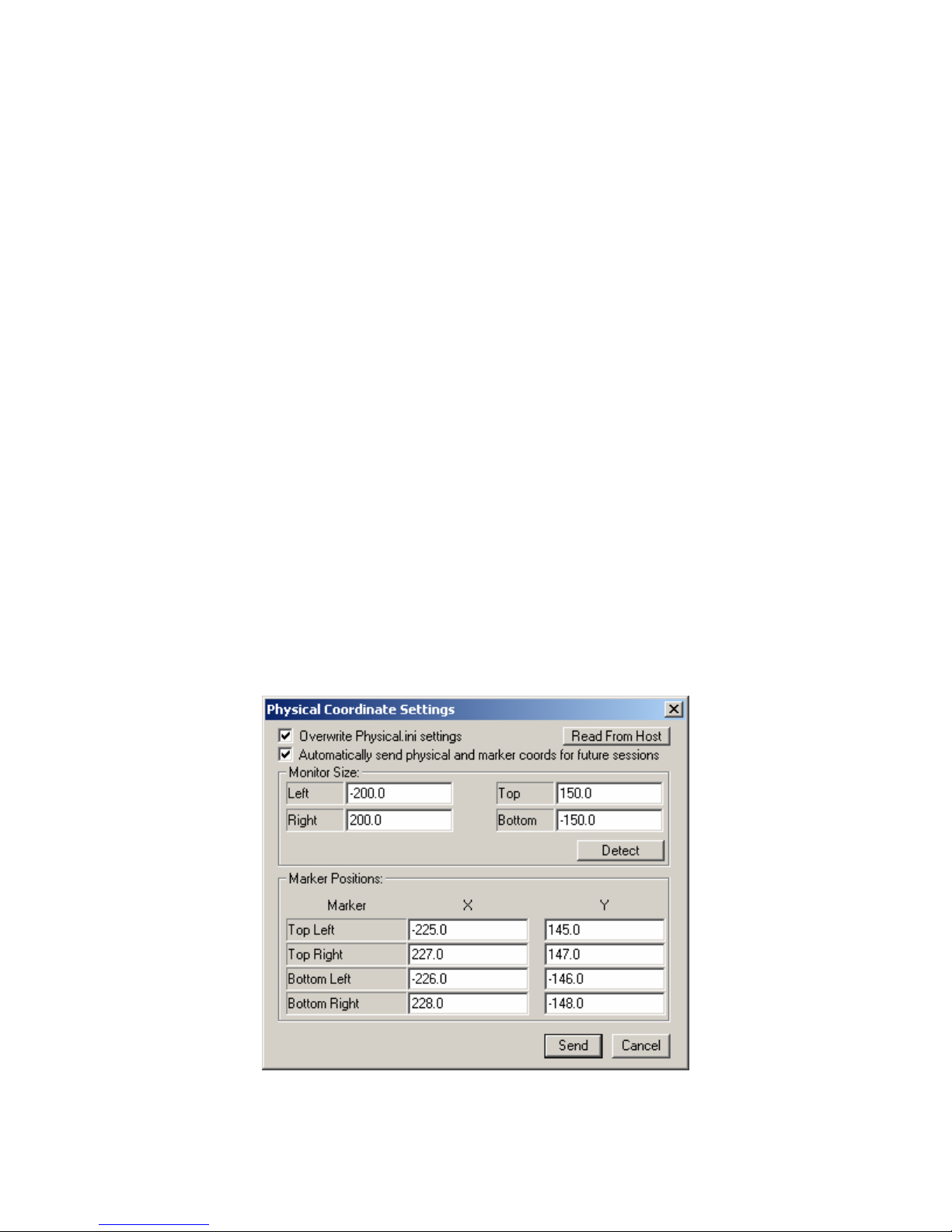
4.5.2 Physical Coordinates Settings
A good calibration requires the users to have a proper physical setup for the
experiment. By default, the tracker will read in the “marker_phys_coords” and
“screen_phys_coords” values in the physical.ini at the current EyeLink host
directory (by default “c:\eyelink2\exe”). Users can also update the physical
setup by clicking “View -> Physical Coordinate Settings” and check the
“Overwrite Physical.ini settings” option. Clicking on the “Read From Host”
button will load in the current values set in the physical.ini file.
Figure
4-7: Updating Physical Coordinate Settings
EyeLink II Scene Camera User Manual © 2004-2007 SR Research Ltd.
39
Page 45
The “Monitor Size” values measure the distance of the visible part of the display
screen edges relative to the center of the screen in millimeters (corresponding to
“screen_phys_coords” command). Enter a negative value for the left edge and
bottom edge distances. Click “Detect” button will let the software automatically
detect the size of the monitor. The “Marker Positions” values are determined by
the physical position of LED markers (corresponding to “marker_phys_coords”
command). The X/Y values in the table refer to the horizontal and vertical
distances in millimeters relative to the center of the screen. Enter a negative
value if the marker is to the left of the center of screen or below the center of
the screen.
To apply changes in the physical coordinate settings, press the “Send” button.
The modified settings will be used for the current session. Always redo a
calibration if the physical setup values are updated. Enable the “Automatically
send physical and marker cords for future sessions” option if the modified
settings should persist over future sessions.
4.6 Depth Correction Mode
The depth correction mode ( ) is used to correct for depth parallax in the scene
camera overlay and
scene camera recording, if “cyclopean gaze cursor” option is enabled, the “ball”
of the cursor is positioned at the average X and Y gaze position of the two eyes.
When a participant is fixating on a target at an uncalibrated plane, the ball of
the cursor may be drawn at a different position from where the participant
intends to look at. This error is caused by the difference in the viewing angles
between the scene camera and the eyes (i.e., parallax error). Therefore, a depth
correction following calibration is critical for any experiment involving viewing
targets at different viewing depths.
must be performed prior to each recording session. In a
EyeLink II Scene Camera User Manual © 2004-2007 SR Research Ltd.
40
Page 46
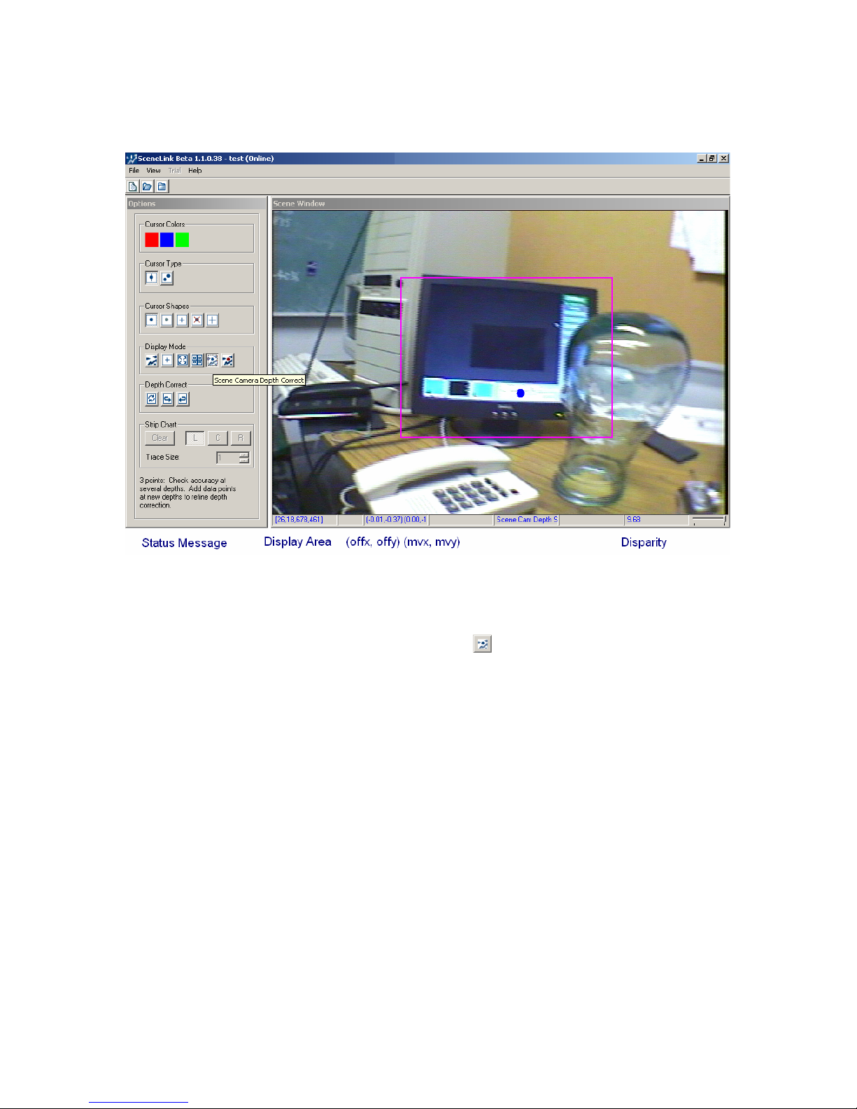
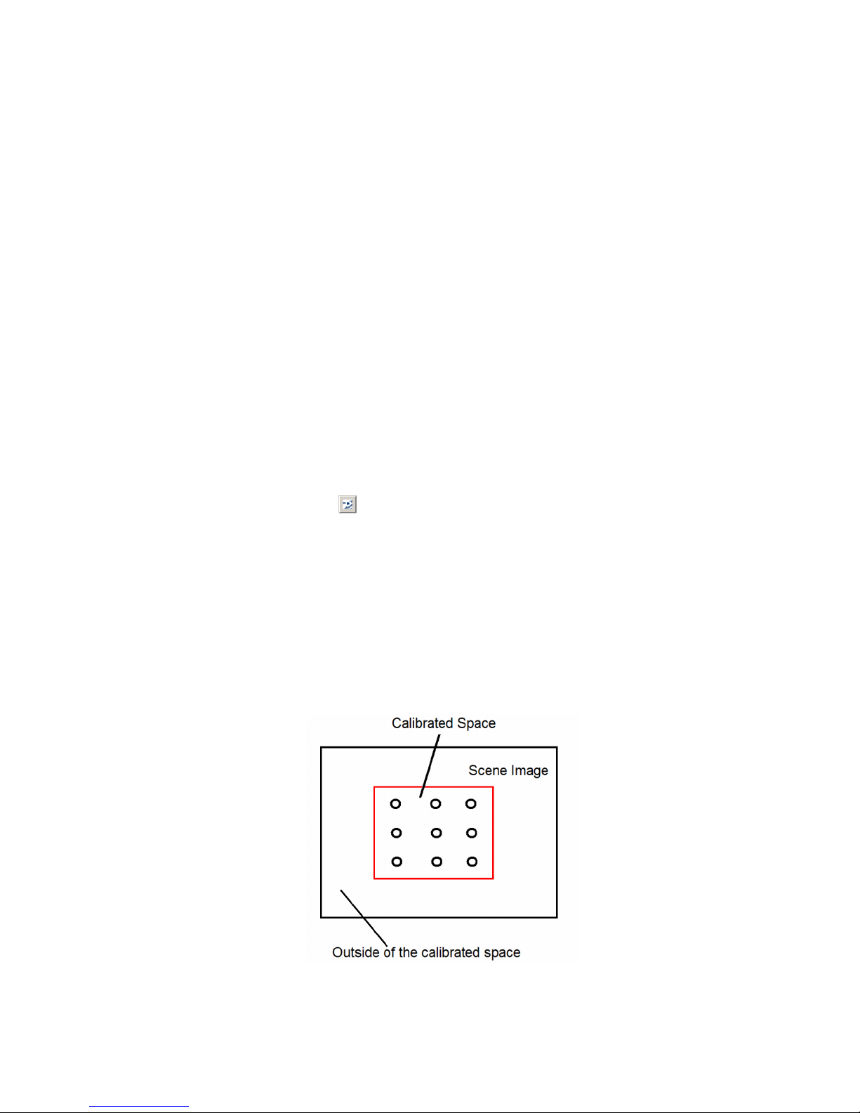
Figure 4-8. Calibrated Space Viewed in the Overlay
Display
Figure
4-9. Scene Camera Depth Correction
Follow the following steps to correct for parallax error:
- Click on the depth correction mode (
) button on the scene camera
application. If a calibration has been successfully done, a red box will be
displayed on the video screen representing the calibrated space (see
Figure 4-8). The drawing of this box can be toggled on/off by clicking on
the “Hide Calibrated Area” box.
- The first data point of depth correction, behaving like a drift correction
point, performs a global offset adjustment and changes the value of “offx”
and “offy” in the fitting function. The subsequent data points change the
correction slope “mvy” (and “mvx” as well if ‘
scenecam_depthfix_xy’ is
enabled). Therefore, the first data point in the depth correction
procedure should be placed as close to the calibrated plane as possible
whereas the subsequent points could be chosen from very different depth
levels within the calibration space to make the correction more precise.
For a calibration that is done close to the participant, the second point of
the depth correction should be placed at a point in the calibrated space
that is distant from the participant, and vice versa. As a rule of thumb,
EyeLink II Scene Camera User Manual © 2004-2007 SR Research Ltd.
41
Page 47

collecting 4-5 points across various depth planes should be sufficient for
a good depth correction.
- Specify a fixation target at a particular depth within the calibrated space
and ask the participant to fixate on the target precisely. While the
participant is fixating on the target, move the display PC mouse, place
the cursor over the fixation target and click the left mouse button once
only (see Figure 4-8). One correction data point will be added with each
mouse click.
- The depth correction will fail if no stable fixation data is available or the
distance between the fixation target and the current gaze cursor position
is too large. Pay attention to the status message printed below the depth
correction buttons to make sure the data point is successfully added and
that only one data point is added for each sampling.
Typically, the user will perform a scene camera depth correction after
calibration and validation and then proceed with data acquisition. However,
depth correction can be improved or redone if necessary by entering this mode
again. When in the depth correction mode, several active or grayed buttons,
grouped under “Depth Correct”, are displayed in the left panel of the scene
camera application.
- If the user wants to restart the depth correction anew, simply click the
“Clear & Restart” button (
). This will clear the previous depth
correction data points as well as the offset and slope values. A new data
collection process can be started and another set of offset/slope
parameters be derived to correct for parallax error.
- The user may also keep the existing data points and improve upon the
last fit by adding more data points. This is done by clicking on the
“Improve Last Fit” button (
). While collecting more data points, the
user can click “Clear & Restart” button to remove all existing data points
and to start the data collection afresh, or abandon the new data points
and revert to the previous parameters by clicking on the “Revert” button
). Clicking the “Revert” button again will keep the previous data
(
points as well as the more recent data points collected – this is indicated
by the text messages displayed at the bottom of the tracker screen.
4.7 Output Mode
The output mode ( ) is used to manually track and record eye movements.
This mode must be entered before a trial recording can be performed.
EyeLink II Scene Camera User Manual © 2004-2007 SR Research Ltd.
42
Page 48
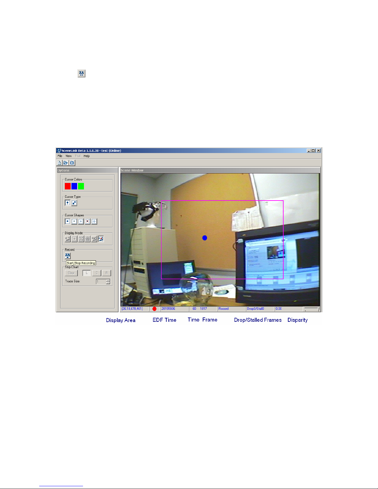
4.8 Record Mode
Recording of eye movements and scene camera video starts when the record
mode (
will be displayed so that the user can insert a message to the EDF file at the
beginning of each trial. The recording can be stopped by pressing this mode
button again. For each entry of the recording mode, one scene camera .AVI file
is created while only one eye movement data file is saved for the whole
recording session.
data, the start and stop recording operations should be done on the display PC
only.
) button is pressed. If the “Log Messages” option is enabled, an edit box
For the integrity of eye movement and scene camera video
Figure
4-10. Recording Screen
In the recording display, the gaze cursor will be overlaid on the scene camera
image, with the calibrated space marked as a box in the center of the recording
display (see Figure 4-9). The status bar of the video window displays the
following information during recording: display area, current EDF time of
recording, time (in seconds) into recording and the current frame number of
scene video, count of dropped or stalled video frames, and the current vergence
information (disparity in the horizontal gaze position between the two eyes).
Please note that a warning message “GAZE CURSORS DISABLED INI FILE OR
COMMAND” will be printed out on the host screen if the recording is controlled
by the SceneLink application – this is done by design.
EyeLink II Scene Camera User Manual © 2004-2007 SR Research Ltd.
43
Page 49
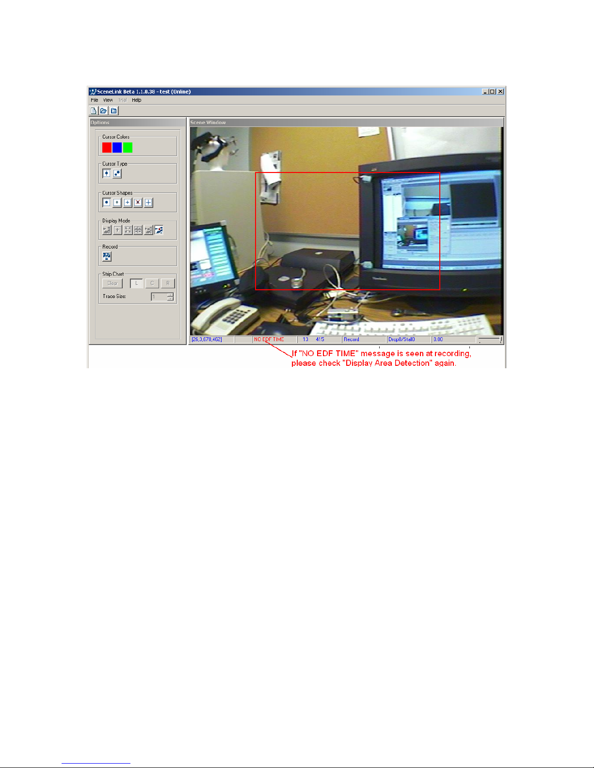
4.8.1 Problem with Recording
Figure
4-11. Problem during Recording: "No EDF
Time"
As mentioned earlier, the gaze cursor will be drawn overlaid on top of the scene
video when the recording starts. If the gaze cursor disappears when the record
button is pressed and a red “NO EDF TIME” warning message is shown at the
scene window, this means that the SceneLink application cannot detect the
time code for synchronization between the eye data and scene video. To fix this
issue:
1) Close the current experiment session. From the application menu bar,
click “View -> Preferences” and select the “Advanced” tab of the
preferences dialog box. Set the “Time Code Threshold” to a lower value
(e.g., 430).
2) Redo the display area detection by making the crawling box smaller
(especially the top edge, see section 4.3 “Display Area Detection Mode”).
4.8.2 Synchronization with Third-Party Recording Devices
The SceneLink software allows users to send out synchronization signals to
other third-party data acquisition devices through the parallel port of either the
display computer or the EyeLink host computer. Please make sure you have
installed the DriverLINX Port I/O Driver to support this capability. Before
EyeLink II Scene Camera User Manual © 2004-2007 SR Research Ltd.
44
Page 50

starting a recording session, click “View -> Preferences”. Select the “Advanced”
tab. Check whether the base address of the parallel port is correctly set (LPT1
is typically assigned to the base address 0x378, while LPT2 is assigned to
0x278). Enable the “Start” (sending out a synchronization signal when
SceneLink starts recording), “End” (sending out a signal when SceneLink stops
recording), and “Clear” boxes (sending out a clearing signal 50 msec following
the START or END signal, or BOTH). Now, specify the register (typically “DATA”
register of the parallel port) where the signals should be sent and the intended
TTL Values. Note that the base address and value fields expect a hexadecimal
number (so the user should enter 0x378 instead of 378). The outgoing TTL
signal is sent immediately after the eye tracker starts or stops recording and
marked with a “SCENELINK_TTL [OUT] START_TTL” or “SCENELINK_TTL [OUT]
END_TTL” message in the EDF file.
It is also possible to control the start and end of a SceneLink recording by
external triggers received through the parallel port of the display computer. The
address is typically set to the “STATUS” register of the parallel port. An
incoming signal that matches the prespecified value will initiate a short lead in
the video recording and then start the tracker recording. This input signal is
marked with a “SCENELINK_TTL [IN] START_TTL” message in the EDF file. The
end signal will immediately stop the eye tracker recording; this signal is marked
with a “SCENELINK_TTL [IN] END_TTL” message in the data file. Please make
sure both the start and end trigger signals last at least 50 ms for the SceneLink
display PC to pick up reliably.
4.8.3 Performing Online Drift Correction
During recording, if the user notices excessive drifts in the gaze cursor drawing,
a runtime drift correction can be perform from either the display PC or from the
host PC as shown below. Important: Please be aware that for a recording with
scene camera option, the “Drift Correct” button in the Camera Setup screen
behaves differently from a recording without using the scene camera. After
performing a depth correction, clicking this button will bring up the Scenecam
Depth Setup Screen and erase the original offset and slope parameters of the
fitting function. So please avoid clicking on the “Drift Correct” button on the
Camera Setup screen. Use one of the following two approaches instead.
4.8.3.1 Online Drift Correction from the Display PC
To perform an online drift correction from the SceneLink application, first
specify a fixation target within the calibrated space at a particular depth
(preferably at the calibration depth) and ask the participant to fixate on the
target precisely. While the participant is fixating on the target, move the display
PC mouse, place the cursor over the fixation target and click the right mouse
button once. The drift correction may fail if there is no stable fixation data or if
EyeLink II Scene Camera User Manual © 2004-2007 SR Research Ltd.
45
Page 51
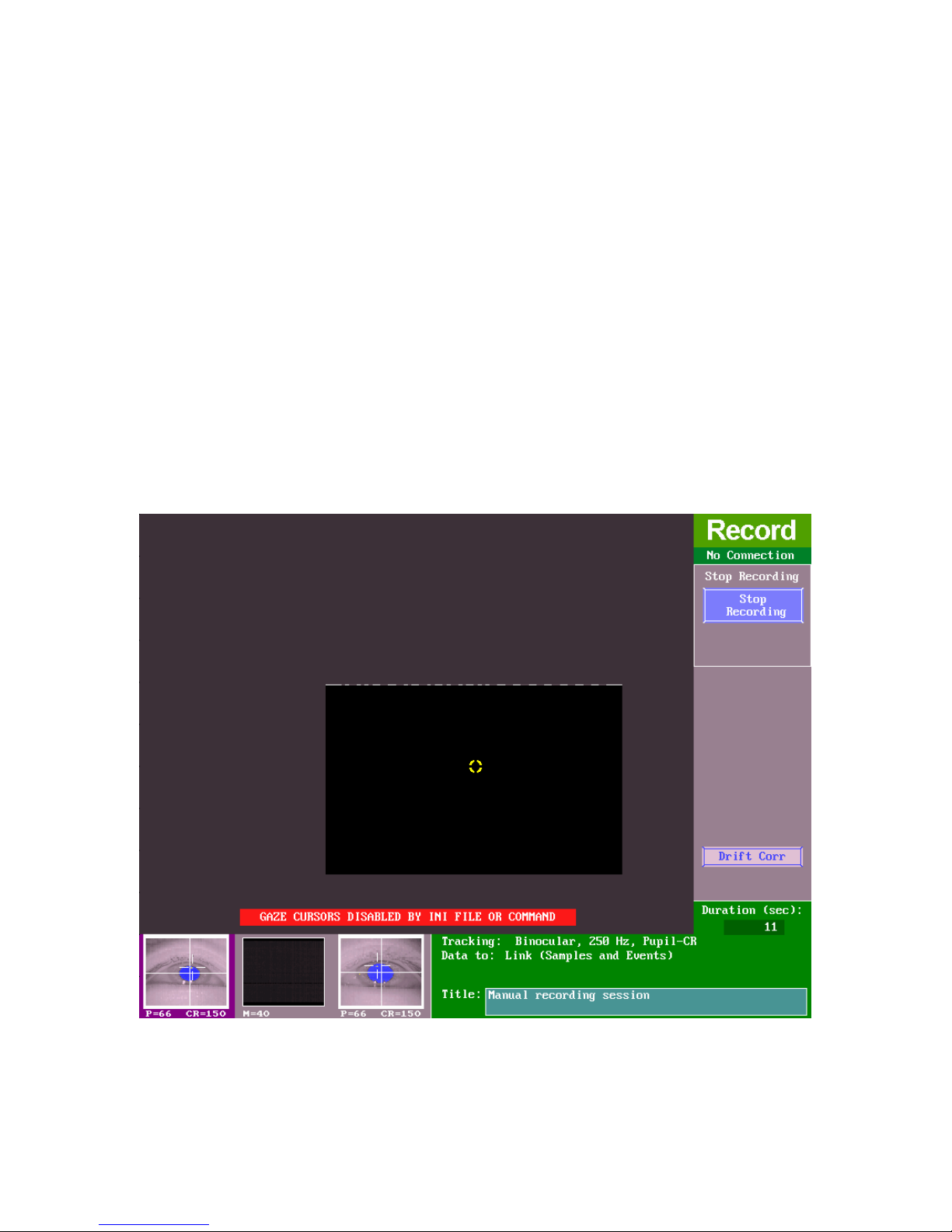
there is a large error between the current fixation and the target item. By
default, the maximum acceptable error value (set by the
‘scenecam_dcorr_maxangle’ command) is 20˚.
4.8.3.2 Online Drift Correction from the Host PC
Follow the steps below to perform an online drift correction from the EyeLink host PC.
- Click on the “Drift Corr” button on the Record screen of the host PC,
which will flash periodically if enabled (see Figure 4-10).
- Move the mouse cursor (yellow circle) of the host PC over the intended
drift correction target on the scene camera video, preferably a point on
the depth plane where the participant was originally calibrated, and
instruct the participant to fixate on the target precisely. Press the left
mouse button only once when the participant fixates stably.
- If the data quality is not improved following the drift correction, the
experimenter should check the camera setup and redo calibration,
validation, and depth setup.
Figure
4-12. Performing Online Drift Correction
EyeLink II Scene Camera User Manual © 2004-2007 SR Research Ltd.
46
Page 52
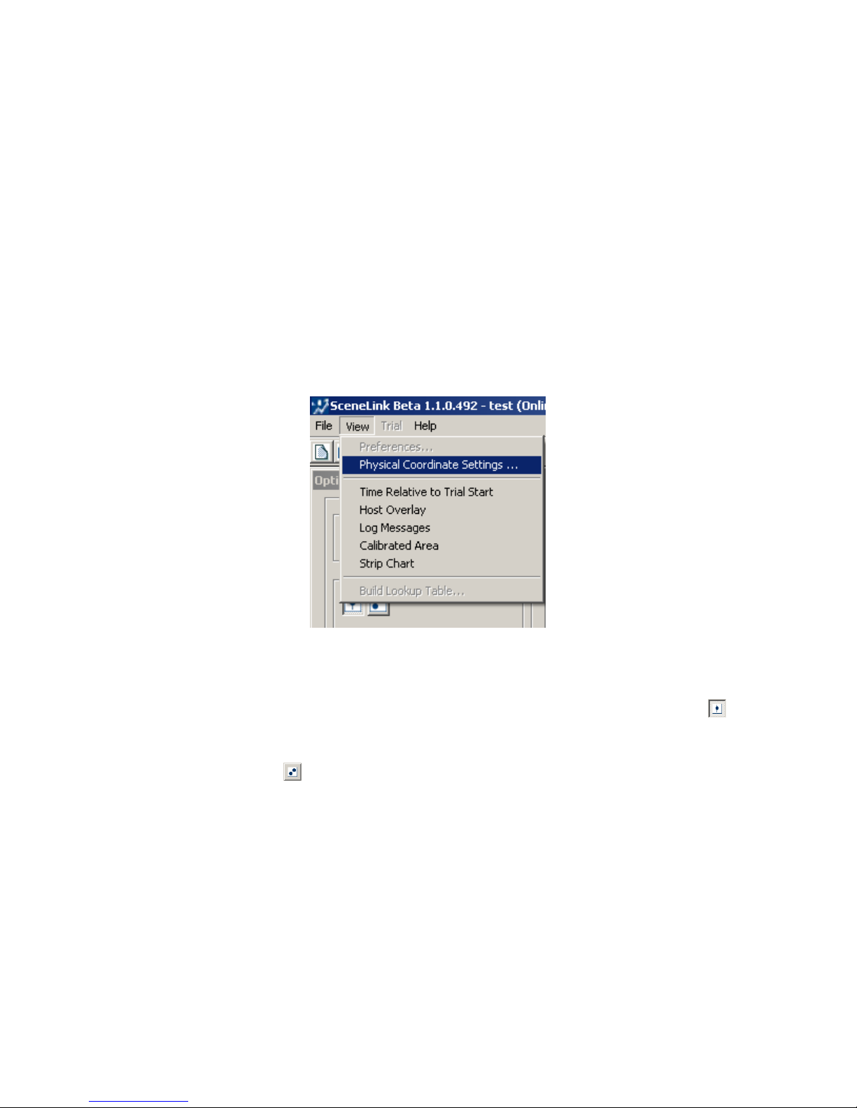
4.9 Recording Options
Several configuration options, such as enabling overlay graphics, logging
messages (see Figure 4-13), and configuring cursor color and shape, are
available for SceneLink recording (see Figure 14). Enabling “Time Relative to
Trial Start” option in the View menu will display the milliseconds elapsed since
the start of the trial in the recording status bar instead of the absolute EDF
time. The “Host Overlay” option, if checked, draws the overlay graphics from
the host PC on top of the recorded scene camera video. This option is handy for
users who want to record the video clips of the scene with the gaze position
overlaid and do not wish to use SceneLink application to do the analysis. The
“Log Messages” edit box, if enabled, allows the user to send a message to the
EDF file at the beginning of each recording trial. The “Calibrated area” box, if
checked, will display the calibration area drawing.
Figure
4-13. Preference Settings
Gaze cursors for use in the scene camera overlay have a selectable shape and
color to improve visibility. In a binocular recording, if the cyclopean cursor (
)
button is enabled, the tracker will draw a single gaze cursor, representing the
average of the two eyes; otherwise, the gaze positions will be drawn separately
for each of the eyes (
). Several colors can be selected for a cyclopean or each
of the binocular gaze cursors. The color of the left, cyclopean, and right eye
gaze cursor can be set by clicking on one of the three colored buttons. Gaze
cursor may appear as a solid circle, a halo, a small cross hair, a full screen
cross hair, or be disabled. Select the cursor appearance by clicking on the
appropriate button in the “Cursor Shapes” section.
EyeLink II Scene Camera User Manual © 2004-2007 SR Research Ltd.
47
Page 53
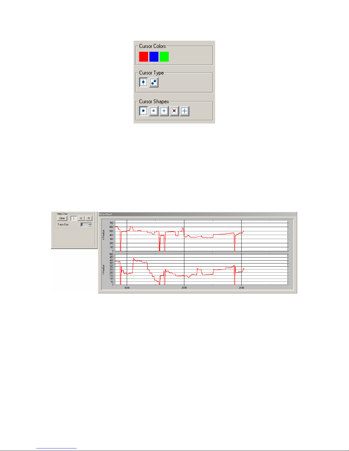
Figure
4-14. Optional Settings for SC Recording
4.10 Strip Chart
The SceneLink strip chart plots the X and Y gaze position as a function of the
current tracker time (in seconds) in a separate window (see Figure 4-15). This
window only appears when in the output / record modes and in the playback
mode of the SceneLink application. To show strip chart window, make sure the
“View -> Strip chart” option on the application menu is checked.
Figure
Several aspects of the strip chart display can be modified. User can choose to
display the left-eye (L) and/or right-eye (R) position traces, or the cyclopean (C)
gaze position traces. The thickness of position traces can also be adjusted. See
“View -> Preferences” for more options on the strip chart (Section 3.6
“Configuring SceneLink Options”).
4.11 Closing Recording Session
A recording session can be closed by clicking “File → Close”. This will close all
of the EyeLink and scene camera recordings. The EDF file will also be
EyeLink II Scene Camera User Manual © 2004-2007 SR Research Ltd.
4-15. SceneLink Strip Chart Window
48
Page 54
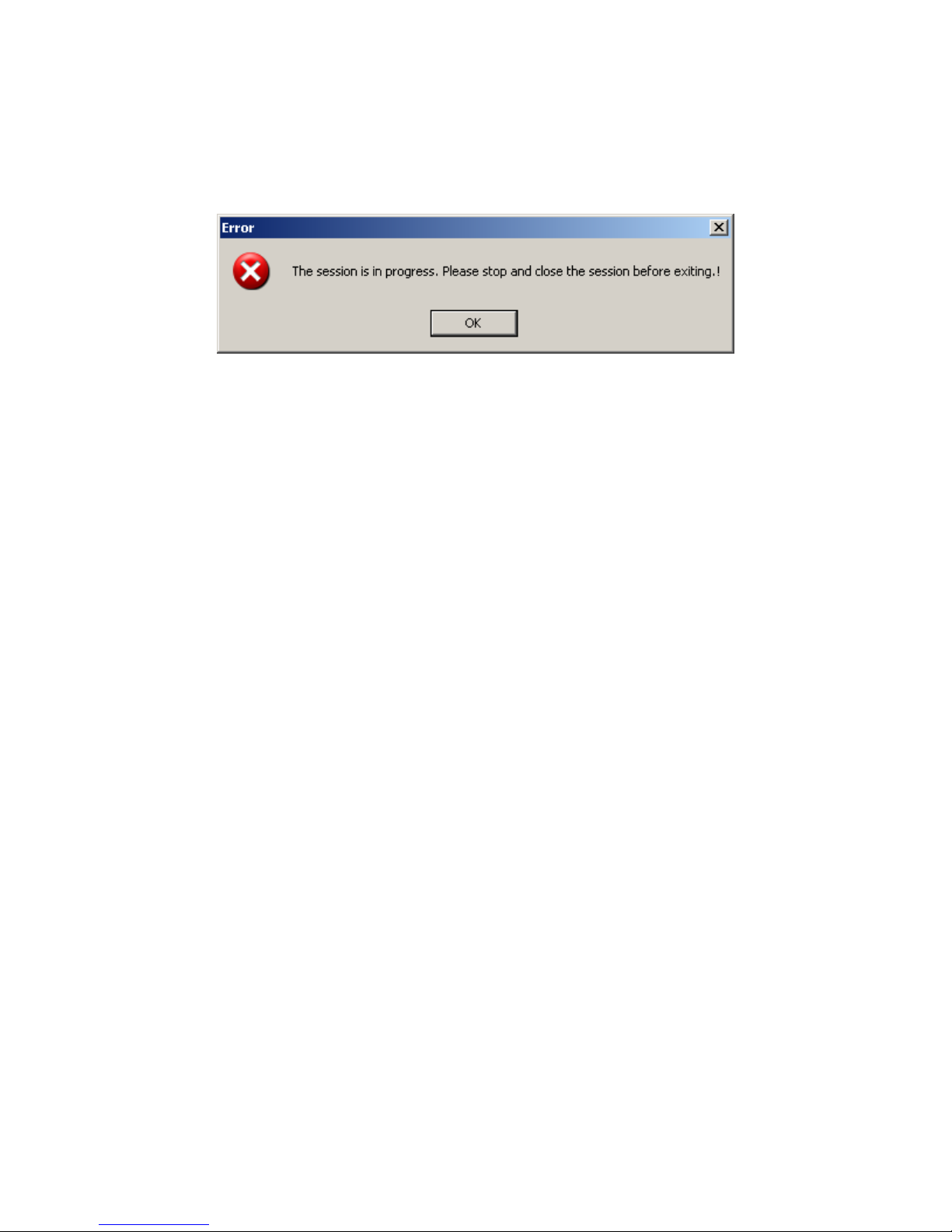
transferred from the host PC to the directory where the videos are stored.
Please note that pressing this menu will give the following error if trial recording
is still in progress (see Figure 4-12). Press the “Record” button to stop
recording before the session can be closed.
Figure
4-16. Error in Closing a Recording Session
4.12 Exiting the SceneLink Application
Before exiting the SceneLink software, please make sure you have stopped any
ongoing recording and clicked “File → Close” to close the current recording
session. Click “File → Exit” or the close button on the top-right corner to close
the SceneLink application.
EyeLink II Scene Camera User Manual © 2004-2007 SR Research Ltd.
49
Page 55
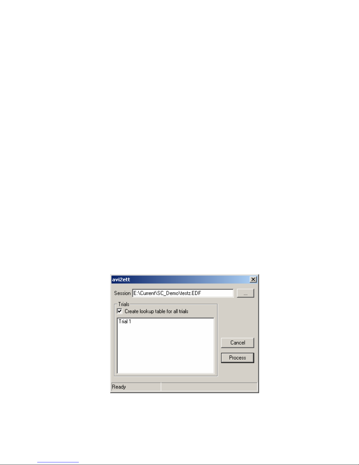
5. Data Playback with SceneLink Application
The SceneLink application can also be used to play back a scene camera
recording. During playback, gaze cursor positioning is generated from merging
EyeLink data file with scene camera video files and is synchronized with the aid
of binary millisecond eye data time code written to every scene camera field.
This synchronization is better than one eye data sample (4 msec). During
playback, the user can also dynamically change cursor type and control
playback speed.
5.1 Opening a Playback Session
To start eye data playback, click on “File → Open Playback Session” from the
SceneLink application menu. (Recent sessions SceneLink recording sessions
are listed in the “File -> Recent Sessions” menu.) This will prompt for an EDF
file name. Go to the directory where the EDF files are stored and select the
target file. Currently it is assumed that the EDF file name matches the .avi file
name and that these files are stored on the same directory.
To run a synchronized playback of eye movement data over the scene video, a
file containing a lookup table between the scene camera frame number and
EDF time should be created. To do this, click “View -> Build Lookup Table”
from the application menubar. In the following “avi2ett” dialog box, set the
“Session” field to the EDF file (with path information). The user can choose to
process all trials by checking “Create lookup table for all trials” checkbox or to
select some of the trials in the list to process those selected ones only.
Figure
EyeLink II Scene Camera User Manual © 2004-2007 SR Research Ltd.
5-1. Creating Lookup Table for a Recording
50
Page 56
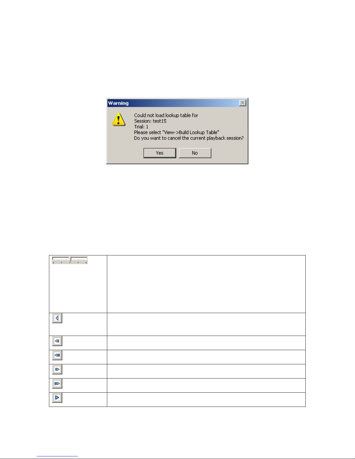
Note that this should be done before running the playback session. A warning
dialog (see Figure 5-2) will be displayed if the files containing look up table are
missing from the directory. If this warning is given, press “Yes” button
(recommended) to close the current playback session so that the look up table
can be created. If you however wish to ignore this warning and continue the
playback session, press “No” button.
Figure
Table
5-2. Error in Finding Fame-to-Time Lookup
5.2 Playing back a Recording Session
If the EyeLink data file and corresponding scene camera video file(s) are loaded
without any problem, the beginning of the first trial is displayed in the video
window. The following buttons can be used to control the playback behaviors
for each trial.
Play Speed Control: Adjusts the speed of playback. Normal
playback speed if the control is set in the middle, faster
playback speed if moved to the right end and slower speed if
moved to the left end. The five marked tick positions
correspond to 10%, 50%, 100%, 150%, and 200% of normal
playback speed.
Rewinding Control: Stops playback and rewinds to the
beginning of the file or trial.
Fast Backward Control: Steps back 5 frames of video.
EyeLink II Scene Camera User Manual © 2004-2007 SR Research Ltd.
Backward Control: Steps back 1 frame of video
Fast Forward Control: Steps forward 5 frames of video.
Forward Control: Steps forward 1 frame of video.
Play Control: Starts playing back the trial data.
51
Page 57
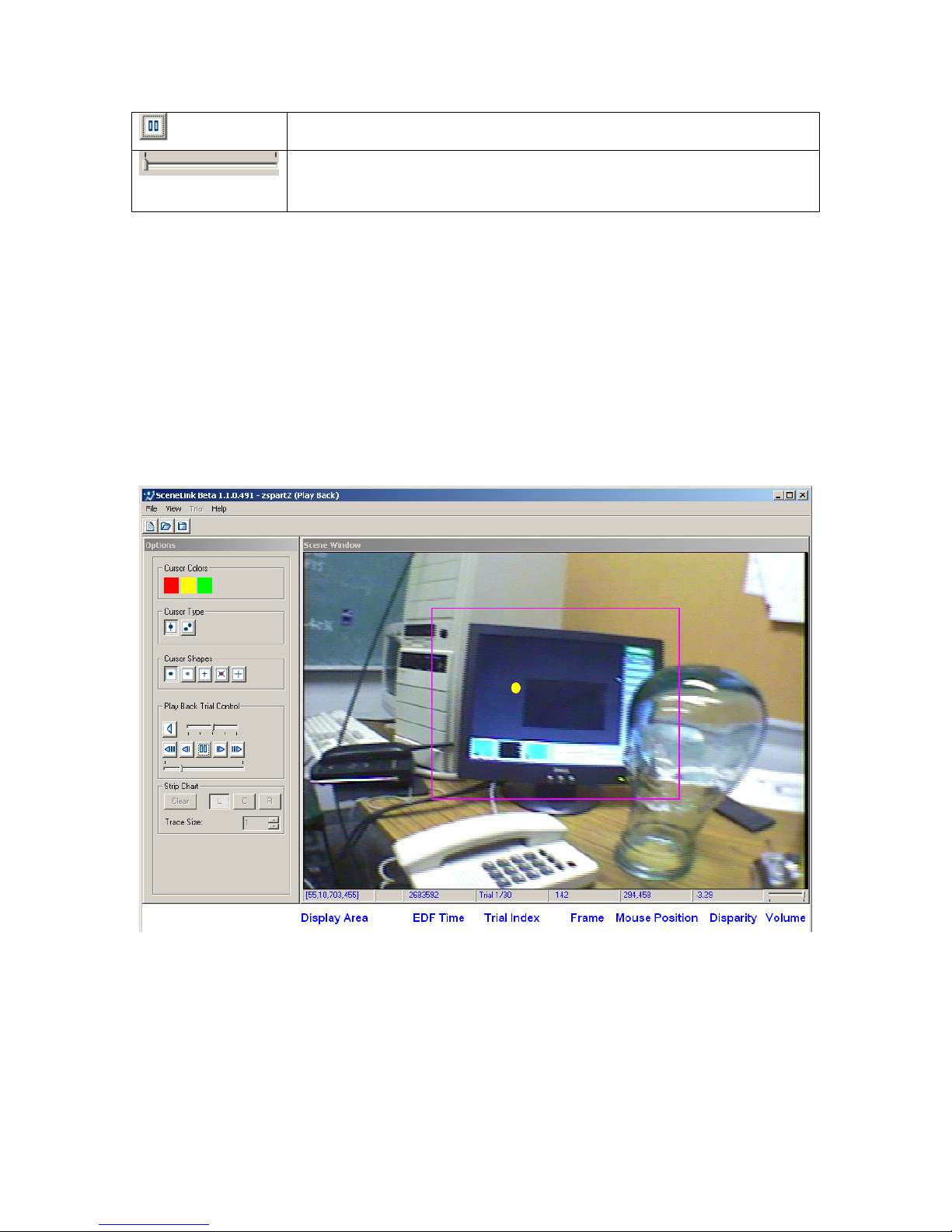
The status bar of the video window displays the following information during
playback: display area, EDF time of the video frame, current trial index, frame
number of scene video in the trial, position of the mouse cursor in the video
coordinate, and the current vergence information (disparity in the horizontal
gaze position between the two eyes). If the corresponding .ETT file, which
contains the frame-time lookup table, is not found for the trial, the conversion
between EDF time and scene frame is not supported. Instead of the actual
frame number of the video, an “Unknown Frame” message is displayed.
Pause Control: Pauses the playback.
Seek Control: Jumps to an intended position in a trial
recording.
Table 1. Playback Trial Control
Figure 5-3. Scene Camera Recording Playback
As in data recording, the appearance of gaze cursor can be changed flexibly
during playback (see section 4.10 recording options). If your recording session
contains audio data, the audio stream will also be played during playback. To
ensure the audio data is played correctly, make sure your audio device setting
is correct (View -> Preferences -> “Audio Output”). In addition, you should
EyeLink II Scene Camera User Manual © 2004-2007 SR Research Ltd.
52
Page 58
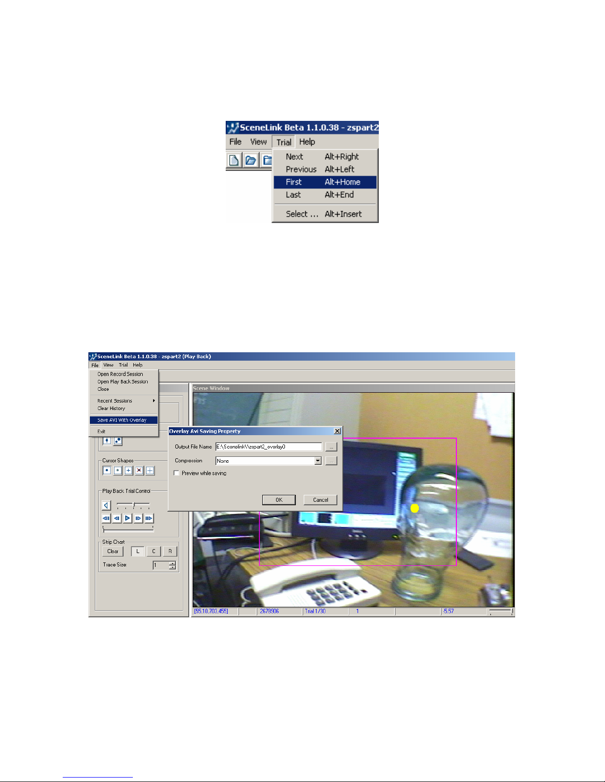
check whether the power of the speaker is turned on and the speaker volume is
loud enough. The volume control at the bottom-right corner of the Scene
Window should also be set to the right end.
Figure
5-4. Trial Navigation Controls
For a SceneLink recording containing multiple trials, navigation between trials
can be done through the “Trial” menu (see Figure 5-4). User can jump to a
particular trial by choosing “Trial -> Select …” option.
5.3 Saving a Recorded Trial
Figure
5-5. Saving a Recording Trial as an AVI File
To save an .avi file for the trial recording, user can select “File -> Save AVI with
Overlay” (see Figure 5-5). The saved video clip contains both the scene video as
well as the overlay graphics such as EDF time, current gaze position, and
EyeLink II Scene Camera User Manual © 2004-2007 SR Research Ltd.
53
Page 59

calibrated region. To reduce the size of the saved overlay file, the user can
choose a video codec for file saving. If “Preview while saving” option is checked,
playback may pause briefly when saving the .avi file with the overlay graphics
on; the saved AVI file, however, will play fine. IMPORTANT! When archiving a
SceneLink experiment data, please make sure the original EDF file and video
files created during data collection are saved.
5.4 Mapping Gaze Data to Digital Video Coordinates and Getting Frame
Number in the ASC File
The SceneLink application records eye-movement data in the resolution set in
the display screen (e.g., 1024 * 768). The user can use EDF2ASC utility to
convert the coordinate of eye data into the digital video coordinate (720 * 480).
Once a lookup table is created for synchronized playback of eye movement data
over the scene video (see section 5.1), the EDF2ASC converter can also be used
to insert scene camera frame number messages in the ASC file. The following
command line switches can be used with the EDF2ASC converter.
-gazemap outputs gaze data in avi coordinates (-g can also be used instead)
-insertframe inserts frame number (-i can also be used instead)
-scenecam same as using -gazemap -insertframe together
The following modifications have been introduced to the Data Viewer so that
scene camera video information can be extracted.
1) Two new options “Enable SceneLink Gaze Mapping” and “Generate
SceneLink Frame Message” are added to the Data Loading preferences of
Data Viewer. The former allows users to specify in data viewing session
options to load EDF file with mapped gaze data to scene video
coordinates. The latter allows the user to specify in data viewing session
options to generate frame number messages when loading file. Please
make sure you have made these changes before loading the intended
EDF file.
2) The following variables are added to the Sample Report and
Saccade/Fixation Report.
• Sample Report:
EyeLink II Scene Camera User Manual © 2004-2007 SR Research Ltd.
54
Page 60

VIDEO_FRAME_INDEX Index of the video frame that was visible at the sample
time.
VIDEO_NAME Name of the video frame that was visible at the sample
time.
• Fixation and Saccade Reports:
VIDEO_FRAME_INDEX_START
Index of the video frame that was visible at the
start of the eye event.
VIDEO_FRAME_INDEX_END Index of the video frame that was visible at the
end of the eye event.
VIDEO_NAME_START Name of the video frame that was visible at the
start of the eye event.
VIDEO_NAME_END Name of the video frame that was visible at the
end of the eye event.
5.5 Exiting the SceneLink Application
Before exiting the application by clicking “File → Exit”, please make sure you
have closed all of the playback activities and clicked “File → Close” to close the
current playback session.
EyeLink II Scene Camera User Manual © 2004-2007 SR Research Ltd.
55
 Loading...