


4860 Maximum Power Point Tracking
(MPPT) Series
CYNETIC 12-24-36-48V 60A 150V
User Manual
Model
Batte ry vol ta ge
Max. so la r panel v ol tage
Max. in pu t power
Charg ing curre nt
Disch arging cu rrent
ML486 0
12V/2 4V /36V/48 V
150V (2 5° C), 145 V (- 25 °C)
800W/ 12 V; 1600 W/ 24 V; 2400 W/ 36 V; 3200 W/ 48V
60A
20A
Spe cific ation ve rsio n numbe r:V1. 02 If the re is any c hange , witho ut noti ce
Cod e:1.1 .24.0 1492

Dear users,
Thank you for choosing our product!
Safe ty Instructions
1. As thi s co nt rolle r de al s wi th voltag es t ha t excee d th e to p limit for h um an s af ety,
do not op er at e it before r eading th is m an ua l caref ul ly a nd comple ti ng s af ety
opera ti on t ra ining.
2. The co nt roller has no i nt ernal com po ne nt s that need m ai nt enance or s er vice ,
thus do n ot a tt empt to d is as se mble or rep air the con tr oller.
3. Inst al l th e co ntrol le r in doors, and av oi d co mponent e xp os ure and wat er
intru si on .
4. Duri ng o pe ra tion, the r ad ia tor may rea ch a ver y hi gh t emperat ur e, theref ore
insta ll t he c on troll er a t a pl ace with go od v en tilatio n co nd it ions.
5. It's reco mm en de d that a fuse o r br eaker b e in st alled out si de t he c ontro ll er.
6. Befo re i nstalling a nd w ir ing the con tr ol ler, make sure to d isconnect t he
photo vo ltaic arr ay a nd t he f use or brea ker clo se t o th e batte ry termi na ls .
7. After in st al la tion, che ck i f al l connectio ns a re solid an d re liable so as to a vo id
loose c on ne ct ions that m ay g iv e rise to d an ge rs c au sed by heat a cc um ulation.
War ni ng : means the operati on i n qu estion is dangero us , an d
you should get p ro pe rl y prepar ed b efore proceedin g.
Note: mean s th e op er ation in questi on m ay c au se damage.
Tips: mean s ad vi ce or instructi on f or t he o perator.
!
Table of Contents
1. Pr oduct I ntrod uc tio n
1.1 P roduc t Ove rvie w
1.2 P roduc t Fea tures
1.3 E xteri or a nd In ter face s
1.4 I ntrod uct ion to Ma ximum P owe r Poi nt Tra cki ng Tec hno lo gy
1.5 C hargi ng St age s Intro ducti on
2. Pr oduct I nstal latio n
2.1 I nstal latio n Preca uti ons
2.2 W iring S pecif icati ons
2.3 I nstal latio n and Wir ing
3. Pr oduct O perat ion and D ispla y
3.1 L ED Indi cator s
3.2 K ey Oper ati ons
3.3 L CD Di splay a nd O per ation s
3.3 .1 Menu B lock Di agram
3.3 .2 Main M enu 23
3.3 .3 Real -Ti me Moni torin g
3.3 .4 Para met er Se tting s
3.3 .5 Cont rolle r Cha rging a nd Disc hargi ng Re lat ed Paramet ers S ettin g Descr iptio ns
3.3 .6 LCD Sc ree n Bac kligh t Time Se tting
3.3 .7 "Cle ar Hist orica l Dat a" and "R ese t to Facto ry Set tings "
3.3 .8 Load M ode
3.3 .9 Stat ist ic Data
3.3 .10 His toric al Data o f the C urren t Day
3.3 .11 Dev ice Inf ormat ion
3.3 .12 Blu etoot h Conne cti on Stat us
4. Pr oduct P rotec tion Fu nctio n and System M ain tenan ce
4.1 P rotec tio n Funct ions
4.2 S yst em Main tenan ce
5. Pr oduct S pecif icati on Para met er s
5.1 E lectr ic Para met er s
5.2 B atter y Type De fau lt Para met er s
6. Co nvers ion Eff icien cy Cur ve
6.1 1 2V Syst em Co nvers ion Eff icien cy
6.1 2 4V Syst em Co nvers ion Eff icien cy
6.3 4 8V Syst em Co nvers ion Eff icien cy
7. Pr oduct D imens ions
1
1
1
2
2
4
5
5
6
6
8
8
9
10
10
11
12
13
14
14
14
15
15
16
17
17
17
17
18
19
19
20
21
21
21
21
22

1. Produ ct Introd uctio n
1.1 P ro du ct Ov er view
Thi s produ ct can kee p monit oring t he sola r panel 's gener ating p ower an d track ing the h ighes t volta ge
and c urren t value s (VI ) in real t ime , enabl ing t he syst em to cha rge t he ba tte ry i n max imum po wer. It's
des igned t o be used i n off-gr id ph otovo lta ic syst ems t o coord ina te op erati on of the so lar pan el, bat tery
and l oad, fu nctio ning as t he core c ont rol uni t in off- grid ph otovo ltaic s ystem s.
Thi s produ ct feat ures an LC D scree n whi ch can dy namic ally di splay t he oper ating s tatus , opera ting
par amete rs, c ontro ller lo gs, his toric al da ta, con trol par amete rs, etc . Users c an chec k param eters u sin g the
key s, and mo dif y contr ol para met ers to ca ter to dif feren t syste m requi remen ts.
The c ontro ller ut ilize s stand ard Mod bus c ommun icati on pr oto col, ma king it e asy for u ser s to chec k and
mod ify sys tem par amete rs on the ir own. B eside s, with t he free m oni torin g sof tware w e pro vid e, user s'
var ied rem ote m oni torin g nee ds can be w ell sat isfie d.
Wit h compr ehens ive ele ctr oni c fault s elf-de tecti ng func tions a nd powe rfu l elect ronic p rotec tio n
fun ction s built i nside t he cont rolle r, com ponen t damag e cause d by inst allat ion err ors or sy stem fa ilu res
can b e avoid ed to the g reates t exten t possi ble.
1.2 P ro du ct Fe at ures
1.3 E xt er ior and I nt er faces
Wit h the adv anc ed dual -peak o r multi -peak t racki ng tech nol ogy, whe n the sol ar pane l is sh adowe d or
par t of the pa nel fai ls resu lti ng in mul tiple p eak s on the I- V curv e, th e contr oll er is sti ll ab le to
acc urate ly trac k the max imum po wer poi nt.
A bui lt-in ma ximum p ower po int tra cking a lgori thm can s ignif icant ly impr ove t he en ergy ut ili zatio n
eff icien cy of pho tov olt aic sys tems, a nd rais e the cha rgi ng ef ficie ncy by 15 % to 20% co mpa red w ith t he
con venti onal PW M metho d.
A com binat ion of mu lti ple tra cking a lgori thms en ables a ccura te trac kin g of the op tim um work ing p oint
on th e I-V cur ve in an e xtr eme ly shor t time.
The p roduc t boast s an op timum M PPT tra cki ng effi cienc y of up to 99. 9%.
Adv anced d igi tal pow er supp ly tech nol ogies r aise th e circu it's e nergy c onver sion ef ficie ncy to as h igh
as 98 %.
Dif feren t charg ing p rogra m opt ions in cludi ng thos e for g el batt eri es, sea led bat ter ies a nd open
bat terie s, cu stomi zed one s, etc. a re ava ilabl e.
The c ontro ller fe ature s a lim ited cu rre nt ch argin g mod e. When t he sola r panel p owe r exc eeds a ce rtain
lev el and th e charg ing c urren t is la rger th an th e rated c urr ent , the con troll er wi ll auto matic all y lower
the c hargi ng powe r and b ring th e charg ing c urren t to th e rat ed leve l.
Ins tanta neous l arge cu rrent s tar tup of ca pacit ive l oads is s upp orted .
Aut omati c recog nit ion of bat tery v oltag e is supp or ted .
LED f ault in dicat ors and a n LCD scre en whic h can dis play ab norma lity in forma tion he lp user s to quic kly
ide ntify s ystem f aults .
His toric al data s torag e fun ction i s avail abl e, and da ta can be s tored fo r up to a yea r.
The c ontro ller is e quipp ed with a n LCD scre en with w hich us ers can n ot only c heck de vice op erati ng
dat a and sta tuses , but als o modif y contr oller p arame ter s.
The c ontro ller su pport s stand ard Mod bus pro tocol , ful filli ng the co mmuni catio n needs of v ariou s
occ asion s.
All c ommun icati ons are e lectr icall y isola ted, so u ser s can res t ass ured in u sag e.
The c ontro ller em ploys a b uilt-i n over-te mpera ture pr otect ion m echan ism. Wh en temp eratu re
sur passe s the set v alu e, th e charg ing c urren t wil l decli ne in lin ear pro por tion to t he temp eratu re and
dis charg ing wil l be halt ed so a s to curb t he te mpera ture ri se of th e contr oller, e ffe ctive ly keepi ng the
con troll er from b ein g damag ed by ove rhe at.
Wit h the hel p of an ext ern al batte ry vol tage sa mplin g funct ion, ba tte ry volt age sam pling i s exemp ted
fro m the eff ect of lin e loss, m aking c ontro l more pr eci se.
Fea turin g a tempe ratur e com pensa tion fu nctio n, the co ntrol ler c an auto mat icall y adjus t charg ing a nd
dis charg ing par ame ters in o rder to ex tend th e batte ry's se rvic e life.
The c ontro ller al so feat ures a bat tery o ver-tem perat ure pro tecti on func tion, a nd wh en the ex terna l
bat tery te mpera ture ex ceeds t he set va lue , charg ing a nd di schar gin g will be s hut off s o as to p rote ct
com ponen ts from b eing da maged b y overh eat .
TVS l ighti ng prot ectio n
1
2
3
4
5
6
7
8
9
10
11
12
13
14
15
16
17
16
RS485
③
④
①
②
①
② ③ ④
12V
GND
D-
D+
No.
Def initi on
15
Battery Sampling
①
②
No. No.
Def initi on
①
②
+
17
Controller communication port RJ12 (6-pin)
RS232
①
② ③ ④ ⑤ ⑥
No. Definition
Transm ittin g termi nal TX
Recei ving te rmina l RX
Power sup ply grou nding/
signal g roundi ng
Power s upply g round ing/
sign al grou nding
Power s upply p ositi ve
Power s upply p ositi ve
Fig . 1-1 Pro duct ap peara nc e and i nterf aces
1.4 I nt ro duc ti on to Max im um Po we r Poi nt Tra ck ing Technol og y
Max imum Po wer Po int Trac kin g (MPPT ) is an adv anced c hargi ng te ch nol ogy tha t en abl es the
sol ar pane l to ou tput mo re powe r by a dju st ing t he e lec tric mo dule's o per ating s ta tus . Due to
the n onlin earit y of sola r array s, ther e exi sts a max imum en ergy ou tp ut po in t (ma xi mum p ower
poi nt) on th eir cur ves. U nab le to con tinuo usly lo ck onto t hi s poi nt to cha rge t he batt er y,
con venti on al co ntrol lers (e mp loy ing swi tchin g and PWM c hargi ng tech nolog ie s) ca n't g et th e
mos t of the po wer f rom the s ol ar pa nel . But a sol ar char ge c ont rolle r featu ri ng MP PT
tec hn olo gy can co nt inu ously t rack ar rays' m aximu m po wer p oi nt so a s to get th e ma xim um
amo unt of po wer t o charg e the bat ter y.
1
2
Para llel
ope ratio n
Blac k
Yello w
Red
No. Ite m No. Ite m
Cha rging i ndica tor
Bat tery i ndi cator
Loa d indic ato r
Abn ormal ity ind icato r
LCD s cre en
Ope ratin g keys
Ins talla tion ho le
Sol ar pane l "+" int er fac e
Sol ar pane l "-" int er fac e
Bat tery " -" in terface
Loa d "-" int er fac e
Bat tery " +" in terface
Loa d "+" int er fac e
Ext ernal t emp eratu re samp ling in terfa ce
Bat tery v olt age com pensa tion in terfa ce
RS4 85 comm unica tion in terfa ce
RS2 32 comm unica tion in terfa ce
11
12
13
14
15
16
17
㈠
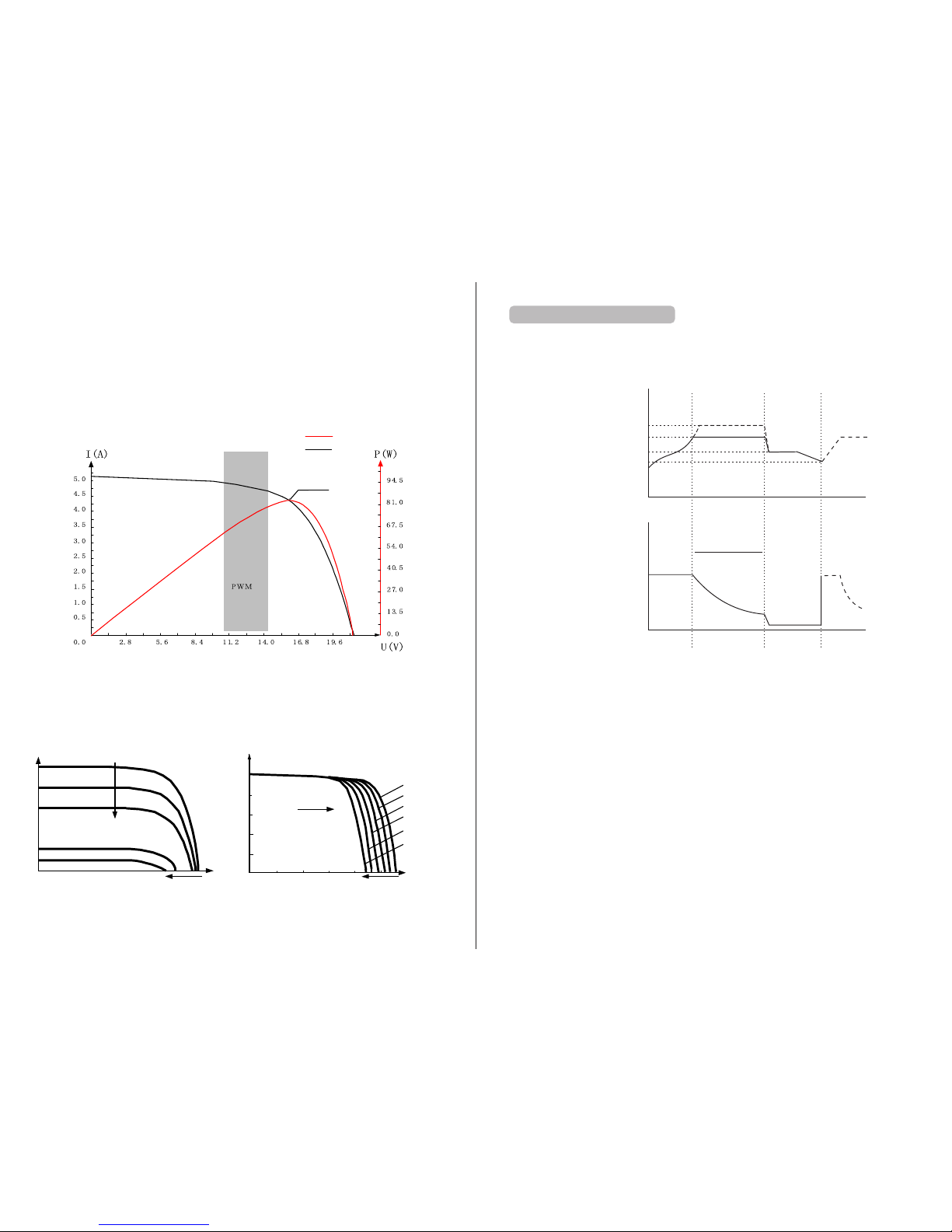
Take a 12 V sys tem as an e xampl e. As the s olar pa nel 's peak v olt age (Vpp) is a ppr oxima tel y 17V
whi le the ba tte ry's v olt ag e is ar oun d 12V, when c hargi ng w ith a c onven tio nal cha rge con tro ller, th e
sol ar pane l's v olt age wil l stay at a round 1 2V, fa ili ng to d elive r the max imum po wer. Howe ver, the
MPP T contr oller c an ov ercom e the pro ble m by adju sting t he sola r panel 's in put v oltag e an d cur ren t
in re al time , rea lizin g a maxim um inpu t power.
Com pared w ith c onven ti ona l PW M con troll er s, th e MP PT co ntrol ler c an make t he mo st of the s ola r
pan el's max . power a nd ther efore p rov ide l arger c hargi ng cu rrent . Ge ner ally sp eak ing, th e latte r can
rai se the en ergy ut iliza tio n ratio b y 15% to 20 % in cont rast wi th the fo rmer.
MPP T point
VP cu rve
VI cu rve
Mea nwhil e, due to c ha ngi ng ambi ent t emper ature a nd illu min ation c ondit ions, t he max. p ower
poi nt vari es fr equen tly, and o ur MPPT c ontro lle r can adj ust par am ete r set tings a ccord in g to th e
env ironm ental c ond ition s in real t ime, so a s to alwa ys ke ep the sy ste m close t o the max . opera ti ng
poi nt. The w hole pr oce ss is ent irely a utoma tic wit hou t the nee d of huma n inter venti on.
U(V
)
I(A
)
20℃
50℃
70℃
60℃
40 ℃
30℃
I (A)
U( V)
Cur rent dec rease s with dw indli ng ligh t
Ope n-circ uit vol tage de creas es with d windl ing lig ht
Wit h temper ature d roppi ng,
cur rent sta ys stab le and
powe r incre ases
Sol ar panel t emper ature
Ope n-circ uit vol tage de creas es with r ising t emper ature
Fig . 1-3 Rel ati on betw een sol ar pane l out put
cha racte risti cs and il lumin ation
Fig . 1-4 Rel ati on betw een sol ar pane l out put
cha racte risti cs and te mp era tu re
Fig . 1-2 Sol ar pane l outpu t chara cteri stic cu rve
1.5 C ha rg ing S tages I nt roduc ti on
As on e of the ch arg ing sta ge s, MP PT can’ t be us ed alon e, but ha s to be use d toget her wit h
boo st char gin g, floa ting ch argin g, eq ualiz ing cha rging , etc . to comp le te ch arg in g the b att er y. A
com plete c ha rgi ng pr ocess i ncl udes: f ast cha rging , su sta ining c har ging an d float ing c hargi ng .
The c hargi ng cur ve is a s shown b elo w:
Bat tery v olt age
Tim e
Max. c urren t
Cumu lativ e time: 3 h
Dura tion: 2 h
(ran ge: 10 to 6 00min )
A
Fast c hargin g
B
C
Boos t
Bulk
Cha rging c urren t
Tim e
Sust ainin g charg ing
Floa ting ch argin g
Equa lizin g charg ing vol tage
Boos t charg ing vol tage
Floa ting ch argin g volta ge
Char ging re turn vo ltage
Fig . 1-5 Bat tery c har ging st ages di agram
a) Fa st char gi ng
At th e fast ch arg ing sta ge , as th e bat tery v olt age has n ot reac hed t he set va lue o f fu ll vo lta ge (i.e .
equ alizi ng/ boo st volt ag e) ye t, th e contr oller w ill per form MP PT char ging on t he ba tter y wit h the
max imum so lar pow er. When t he ba tte ry vol tag e reach es th e prese t value , con stant v ol tag e
cha rging w ill beg in.
b) Su st ai ning ch ar gin g
Whe n the bat ter y volt age r eache s the set v alu e of sust ain ing vol tage, t he cont rolle r wil l switc h to
con stant v oltag e ch arg ing . In this p roces s, no M PPT cha rging w il l be pe rf orm ed, and m eanwh ile
the c hargi ng cu rrent w ill als o gradu ally de creas e. Th e susta ining c hargi ng stag e its elf con sists o f
two s ub-st ages, i .e. equ alizi ng char gin g and boo st char ging, t he tw o of whic h are n ot carr ied out i n
a rep eated m ann er, with t he fo rmer ge tting a ctiva ted o nce eve ry 3 0 days.
B oost ch ar gin g
By de fault , boost c hargi ng ge neral ly last s for 2h, b ut user s can adj ust pre set val ues o f dur ation
and b oost vo ltage p oi nt ac cordi ng to t he ac tual ne eds. Wh en the du ratio n reach es t he se t val ue,
the s ystem w il l the n switc h to fl oat ing cha rging .
3
4

Equa li zing ch ar gin g
War nin g: r isk o f exp losio n!
In eq ualiz ing cha rging , an op en lead -acid b atter y can pro duce ex plosi ve gas, t heref ore t he
bat ter y cham be r sha ll ha ve good v entil ation c ondit ions.
Not e: risk o f equ ipmen t damag e!
Equ alizi ng char gin g may rai se the ba tter y vol ta ge to a l eve l that ma y cause d amage t o sensi tiv e
DC lo ads. Ch eck a nd make s ure t hat all owabl e input v ol tag es of a ll t he lo ads i n the sys tem are
gre ate r than th e set val ue fo r batte ry e quali zing ch argin g.
Not e: risk o f equ ipmen t damag e!
Ove rchar ge or t oo mu ch gas ge nerat ed may da mage ba tte ry pla tes a nd caus e activ e mater ial on
the b atter y plate s to scal e off. Equ ali zing ch argin g to an e xcess ive ly high l evel or f or too lo ng a
per iod may c ause da mage. R ead c arefu lly t he actu al requ ire ments o f the b atter y depl oye d in the
sys tem.
Som e types o f bat terie s benef it fr om regu lar e quali zing ch argin g which c an st ir the el ectro lyte,
bal ance th e bat tery v olt age and f in ish t he elec tro chemi cal rea cti on. Equ alizi ng char ging ra ises th e
bat ter y volt age t o a highe r level t han the s ta nda rd su pply vo ltage a nd g asi fy t he ba tte ry
ele ctrol yte . If the co ntrol le r the n autom ati cally s teers t he batt er y into eq ual izing c hargi ng, the
cha rging d urati on is 1 20 minu tes (de fault ). In ord er to a void to o muc h gener ated ga s or batt er y
ove rheat , equal izing c hargi ng an d boost c hargi ng wo n’t rep eat in on e compl ete c hargi ng cycl e.
Not e:
1) Wh en due to t he i nst allat ion e nviro nment o r worki ng l oad s, th e syste m can't co ntinu ous ly
sta biliz e the bat ter y volt age t o a const ant lev el , the c ont rolle r will in itiat e a timin g pro cess, a nd 3
hou rs aft er th e bat tery v olt age rea che s the set v alue, t he sy stem wi ll auto ma tic ally sw itc h to
equ alizi ng char ging.
2) If n o calib ratio n has bee n done to t he cont rol ler clo ck, th e con troll er will p er for m equal izing
cha rging r egu larly a ccord ing t o its int er nal c lock .
F loati ng char gin g
Whe n finis hing th e susta ining c hargi ng st age, th e contr ol ler w ill swi tch t o float ing c hargi ng in
whi ch the co ntrol ler l owers t he batt er y volta ge b y dim inish ing t he char ging cu rrent a nd ke eps t he
bat ter y volt age a t the set v alue of f loa tin g charg ing vol tag e. In the f loati ng char gin g proce ss, v ery
lig ht char ging is c arr ied out f or the ba tte ry to ma int ain it at f ull sta te. At th is st age, th e loads c an
acc ess alm ost all t he sola r power. I f the l oad s consu me more p owe r than th e solar p ane l could
pro vide, t he co ntrol ler wil l not be ab le to k ee p the b att er y volta ge at the f loa ting ch argin g stage .
Whe n the bat ter y volt age d rops to t he se t value f or re turni ng to boo st char gin g, the sy stem wi ll
exi t float ing cha rgi ng and re ent er into f ast cha rgi ng.
2. Produ ct Inst allation
2.1 I ns ta llati on P rec au ti ons
Be ve ry car efu l when in st all ing the b att er y. For ope n le ad- acid ba tte ries, w ear a p ai r of go ggl es
dur ing ins talla tion, a nd in cas e of cont act w ith bat ter y acid , flush w ith w ater im media tely.
In or der to pr eve nt th e batte ry f rom bei ng sh ort-c irc ui ted , no me tal obj ects sh all be pl aced ne ar
the b atter y.
Aci d gas may b e gener ated du ri ng ba tte ry c hargi ng, thu s mak e sure th e amb ient en viron men t is
wel l venti la ted .
Kee p the bat ter y away f rom f ire s parks , as th e batte ry m ay prod uce f lamma ble gas .
Whe n insta lling t he batt er y outdo ors , take su ffi cient m easur es to k eep the b att er y from di rec t
sun light a nd rain w ater in trusi on.
Loo se conn ectio ns or cor roded w ire m ay caus e exces siv e heat ge nerat ion whi ch may fu rthe r mel t
the w ire's insul ati on laye r and bur n surro undin g mat erial s, and ev en caus e a fire, t her ef ore m ake
sur e all con nec tions a re tigh tened s ecure ly. Wi res h ad bett er b e fix ed pr op erl y with ti es, a nd
whe n needs a rise to m ove t hings , avoid w ire swa ying so a s to ke ep co nnect ions fr om l oos ening .
Whe n conne cting t he syst em , the o utp ut term inals ' volta ge may ex cee d the top l imit fo r human
saf ety. If op er ati on need s to be d one, be s ure to us e ins ulati on tool s and kee p han ds dry.
The w iring t er min als on th e con troll er can be c onnec ted w ith a sin gle bat tery o r a pac k of
bat ter ies. Fo llowi ng desc ripti ons in th is manu al appl y to syst ems e mploy ing eit her a sin gle
bat ter y or a pac k of ba tte rie s.
Fol low the s afety a dvice g iven by t he ba tter y man ufact urer.
Whe n selec ting co nnect ion wir es fo r the sys tem, fo llow th e crite rion th at th e curre nt dens ity is
not l arger t han 4A/ mm2 .
Con nect th e contr oll er's ea rt h ter minal t o the g round .
2.2 W ir in g Speci fi catio ns
Wir ing and i nstal latio n metho ds must c omply w ith nat io nal a nd loca l ele ctric al spec ifica tions .
The w iring s pecif icati ons of th e bat ter y and lo ads m ust be se lecte d accor din g to rate d cur rents ,
and s ee the fo llowi ng tabl e for wir ing spe cific ation s:
Mod el
ML4 860
Rat ed char ging
cur rent
Rat ed disc hargi ng
cur rent
Bat tery w ire
dia meter ( mm2)
Loa d wire
dia meter ( mm2)
Bat tery v olt age
com pensa tion wi re
60A 20A
>15
<5
No re quire men ts
2.3 I ns ta llati on a nd Wiri ng
War nin g: r isk o f exp losio n! Neve r insta ll th e
con troll er and an o pen b atter y in the s ame
enc losed s pace! N or sh all the c ontro ller be
ins talle d in an enc losed s pace wh ere b att ery ga s
may a ccumu late.
War nin g: d ang er of h igh vol tage! P hot ovolt ai c
arr ays may p roduc e a ver y high o pen-c irc uit
vol tage. O pen the b reaker or fu se be fore wi ring,
and b e very c are ful dur in g the w iring p roc ess.
Not e: when i nstal ling th e contr oll er, make
sur e that en oug h air flo ws thro ug h the
con troll er's rad iator, a nd le ave at le as t 150 m m of
spa ce both a bov e and bel ow the co ntrol ler s o as
to en sure na tur al conv ectio n for hea t dissi patio n.
If th e contr oller i s ins talle d in an enc losed b ox,
mak e sur e the box d eli vers re liabl e heat
dis sipat ion eff ect .
≥150mm
Hot a ir
≥150mm
Col d air
Fig . 2.1 Ins talla tion an d heat di ssipa tio n
5
6
!
!
!

Ste p 1: ch oose th e insta llati on site
Do no t insta ll the co ntrol ler a t a place t hat is su bject t o direc t sun light , high te mpera ture or
wat er intr us ion , and mak e sur e the a mbien t envir onmen t is we ll vent ilate d.
Ste p 2: fi t screw s in
Acc ordin g to th e insta llati on dime nsion s of the pr odu ct , use a m arker p en to m ark t he moun ting
poi nts, th en dril l 4 mount ing hol es at the 4 m arked p oin ts, and f it scre ws in .
Ste p 3: fi x the con troll er
Aim t he cont rolle r's f ixi ng hole s at the sc rews fi t in St ep 2 an d mount t he cont rolle r on.
Ste p 4: wi re
Fir st remo ve the tw o scr ews on th e contr oll er, and th en be gin wir ing ope ratio n. In ord er to
gua rante e insta ll ati on safe ty, we r ecomm end the w iring o rder as i ndi cated b y the num bers in t he
fol lowin g diagr am (Fig . 2.3); h oweve r, you c an ch oose no t to foll ow this o rde r and no da mage wi ll
be in curre d to th e contr oller.
Fig . 2.2 Wir ing seq uence
1
2
3
4
5
6
7
8
9
Tempe ratur e
Fig . 2.3 Wir ing seq uence
7
Con necti ng to ext er nal t em per ature s amp ling in terf ace a nd conn ectin g batte ry v olt age
com pensa tion ca ble
Con necti ng comm unica tion ca ble
Con necti ng powe r cable
War nin g: r isk o f ele ctric s hock! W e str ong ly reco mm end t hat fus es or b reake rs be c onnec ted at
the p hotov olt aic arr ay side , load si de and ba tte ry sid e so as t o avoid e le ctr ic sh ock dur ing wir ing
ope ratio n or faul ty oper ation s, and ma ke sure the fu ses and b rea kers ar e in op en s tat e bef ore
wir ing.
War nin g: d ang er of h igh vol tage! P hot ovolt ai c arr ays may p rod uce a ver y high o pen -circ uit
vol tage. O pen the b reaker or fu se be fore wi ring, a nd be ver y careful d uri ng the wi ring pr ocess .
War nin g: r isk o f exp losio n! Once t he ba tter y's p ositi ve an d negat ive ter minal s or le ads tha t
con nect to t he t wo te rmi nals ge t shor t-ci rcuit ed, a f ire or ex plo sion wi ll occu r. Alw ays be ca reful i n
ope ratio n.
Fir st conn ect the b at ter y, then t he so lar pan el, a nd fina lly the l oad. Wh en wiri ng, f ollow t he orde r
of fi rst "+" a nd th en "-".
Pow er on
Af ter c onn ectin g all pow er wire s sol idly an d relia bly, che ck agai n wheth er wiri ng is cor rect an d if
the p ositi ve and ne gativ e pol es are re ver sely co nnect ed. Af ter c onf irmin g that no f aults e xist, f irst
clo se the fu se or bre ake r of th e batte ry, t he n see w hethe r the L ED indi cator s light u p and the L CD
scr een dis pla ys info rmati on. If th e LCD screen f ail s to disp lay inf ormat ion, op en the fu se or bre ake r
imm ediat ely and r ech eck if al l conne ction s are cor rec tly don e.
If th e batte ry f uncti ons n ormal ly, connec t the s olar pa nel. If s un lig ht is int ens e enoug h, the
con troll er's cha rging i nd ica tor w ill lig ht up or fl ash and b egin to c ha rge t he ba tte ry.
Af ter s ucc essfu lly con necti ng the ba tte ry and p ho tov olt aic arr ay, fina lly clo se the fu se or bre ake r
of th e loa d, and th en you ca n man ually t est whe ther th e load ca n be no rmall y turne d on and of f. For
det ails, r efer to i nfo rmati on abou t load wo rki ng mode s and ope ratio ns.
War nin g: w hen t he cont rol ler is in n ormal c ha rgi ng st ate, di sconn ectin g the b atter y will h ave
som e negat ive eff ect on th e DC l oad s, an d in extr eme c ases, t he load s may get d amage d.
Not e that th e bat tery 's fuse or bre ake r sha ll be ins talle d as clos e to the co ntrol ler a s possi ble, an d
it' s rec omm ended t hat the i nstal latio n dista nce be no t more th an 15 0mm.
Not e:
1) If n o tempe ratur e se nso r is conn ected t o the c ontro ller, th e bat tery t emp er atu re va lue wil l
sta y at a defa ult of 25 ° C.
2) If a n inver ter is depl oye d in the sy stem, d irect ly c onn ect the i nve rter t o the b att ery, an d
do no t conne ct it to th e contr ol ler 's load te rmi nals.
3. Produ ct Oper ation and Display
3.1 L ED I nd ica to rs
①
②
③
④
①---
②---
③---
④---
Cha rging m ode
Bat tery s tat us
Loa d statu s
Abn ormal ity ind icati on
PV ar ray ind icato r
BAT in dic ator
LOAD i ndica tor
ERR OR i ndi cator
8
V-c ompen satio n
int erfac e(Bat tery )
R 485 c ommun icati on
int erfac e
S

PV array indicator:
BAT in di cator :
LOA D ind ic ator :
Loa d state
Loa d turne d off
Loa d overl oad ed/ s hort-c ircui ted
Loa d funct ionin g norma lly
ERROR i ndica to r:
Ind icato r state
Off
Stea dy on
Abn ormal ity ind icati on
Sys tem o perat ing nor mal ly
Sys tem m alfun ction ing
3.2 K ey O perat io ns
Main menu
Real-time
monitoring
Load mode
Parameters
setting
Statistic data
Historical data of
the current day
Device
information
Bluetooth connection state
(This menu is available only to the display units with the optional bluetooth function)
Refer to "Usage of Navigation Keys" for operations including entering into and exiting each
of the above menus, related parameters setting, etc.
3.3 L CD Disp la y and Ope ra ti ons
3.3 .1 Menu B lock Di agram
9 10
Ret urn t o pre vio us menu
(ex it with out sav ing)
Ent er into s ub-me nu; set / saveTur n on/
off l oads (i n man ual m ode)
Pag e dow n; de creas e the p ara meter
val ue in set ting
Pag e up; i ncrea se th e par ame ter valu e
in se tting
485:co mmuni catio n

(Thi s menu i s cont ain ed in and s uppleme nta ry to in for mati on of th e main me nu)
In the "m ain menu", t ap " " to enter into t his me nu; co ntinue to t ap " , " to swit ch bet ween
menus;o r tap " " to ret urn to t he "ma in men u".
Displayed item/
parameter
Description
Remarks
1
ChagState: IDLE
Charging state indications:
"IDLE", no charging
"MPPT",MPPT charging
"EQU", equalizing charging
"BST", boost charging
"FLT",floating charging
"LIMIT", current-limited charging
BatVol: 11.6V
Battery voltage
PvVol: 0V
Solar panel voltage
ChagCrt: 0A
Charging current
2
LoadState: OFF
Load in "ON" or "OFF" state
LoadCrt : 0A
Load current
BatSoc: 100%
Remaining battery capacity
DevTemp: 27 ℃
Controller temperature
3
ChagPower: 0W
Charging power
LoadPower: 0W
Discharging power
MinBatVol : 12.5V
The current day's min. battery voltage
MaxBatVol : 13.0V
The current day's max. battery voltage
4
Fault : NULL
“ DEV-OVRTMP”
“ BAT-OVRTMP”
“ PV-OVP”
“ PV-SHTCRT”
“ PV-OC-OVD”
“ PV-MP-OVD”
Not e very
con troll er
has a ll of
the se erro r
cod es. For
det ails, r efer
to th e User
Man ual of th e
cor respo ndin
g con troll er.
“ PV-REV”
Controller error codes:
“ BAT-LDV ”over-discharge
“ BAT-OVD”over-voltage
“ BAT-UVW” under-voltage warning
“ L-SHTCRT” load short-circuit
“ L-OVRCRT”
load over-current
internal over-temperature
battery over-temperature
solar panel overpower
solar panel short-circuit
solar panel over-voltage
solar panel working over-voltage
solar panel reverse-connection
Page
2nd-level
menus
Menu level
Definitions of "main menu" icons
Icon or value
State
Description
Remarks
Ste ady on
"0 ~10 0% "
"0 %"i n slow
fla shing
"100%"in quick
flashing
Nig httim e
Day time
A dyna mic arr ow indi cates c hargi ng is in pr ocess ,
whi le a stat ic one in dicat es othe rwise .
Cur rent ba ttery c apaci ty
Bat tery ov er-di schar ged
Bat tery ov er-vo ltage
A bulb shown as left and a dynamic arrow indicate the
load is switched on.
A bulb s hown as l eft and a s tatic a rrow in dicat e
the l oad is sw itche d off.
Ove rload o r short -circ uit pro tecti on
Day or night indicating icon
Charging current icon
Battery icon and SOC
Load current icon
Load icon and state indication
charging power
load current
Battery voltage
37%
26.8V 11.6V
0W 0A
OFF
0A
37%
Related to
charging
Related to
battery
Related to
load
Solar panel voltage
charging current
Load state
Ste ady on
Ste ady on
Ste ady on
Ste ady on
Qui ck flas hing
3.3 .2 Main M enu
3.3 .3 Real -Ti me Moni torin g
11 12

Displayed item/ parameter
Description
BackLight-T: ON The LCD screen is lit constantly
BackLight-T:
20S
The setting range of LCD screen backlight time is 1 to 600s
①.All voltage values are to be set based on 12V system settings. For example, for a 24V system, if the
over-discharge voltage is to be set to 22.0V, as n=24/12=2, the value needed in line with 12V system settings is
22.0V/2=11.0V, therefore the over-discharge voltage needs to be set to 11.0V.
②.Tap " , " to select the item to be set; then tap " ", and the parameter or sign will flash; continue to tap
" , " to adjust the value, and tap " " again to confirm the setting. (For the setting ranges of related parameters,
refer to "Parameter settings list")
③.For parameters on the current menu, those highlighted are settable, while those underlined are not.
SET
AUTO/SLD
BST:14.4V
LVD:11.0V
Setting icon
Battery type indication
System voltage indication
Boost charging voltage 14.4V
Over-discharge voltage 11.0V
Ent er into t he sett ing men u, tap " , " to m ove to "B ackLi ght-T:2 0S", ta p " "to ent er into t he sett ing
mod e, and ta p " , " to modi fy the va lue wit hin the s ettin g range ( "ON" in dicat es the sc reen wi ll be
con stant ly lit, a nd the ra nge of ba cklig ht time i s "1-60 0" S.). Ta p " " to conf irm the m odifi catio n, or tap
“ ” to ca ncel th e modif icati on.
Parameter settings list
Menu level
Page Item to set
1
Battery system
voltage
BatSysVol :
Battery type
BatType:
Nominal battery
capacity
Capacity :
Device address
Parameter and setting range Remarks
“
12V”12Vsystem
“24V ”24V system
“36V ”36V system
“
48V”48Vsystem
“
AUTO” auto recognition
“SLD”sealed lead-acid battery
“FLD” open lead-acid battery
“GEL” gel battery
“LI ” lithium battery
“USE”user defined
0~9999
± 5
Address: 1~60 ± 1
2
Over-voltage threshold OverVolDsc: 9.0~17.0V
Charging limit voltage ChgLimtVol : 9.0~17.0V
*n,±1
Equalizing charging
voltage
EquChgVol:
9.0~17.0V
Boost charging voltage
BstChgVol :
9.0~17.0V
3
Floating charging
voltage
FltChgVol
:
9.0~17.0V
Boost charging
recovery voltage
BstChgRev
:
Over-discharge
recovery voltage
LowVolRev
:
Under-voltage
warning level
UndVolWrn
:
4
Over-discharge voltage LowVolDsc :
Over-discharge time
delay
LVD Delay:
0~60s
± 1
Equalizing charging
time
Equ-Time:
0~300 MIN
± 1
Boost charging time
Bst-Time: 0~300 MIN ± 1
5
Equalizing charging
interval
Equ-Inv : 0~30 D(days )
± 1
Temperature
compensation
Temp-Com:
-(3~5)mV/℃/2V
± 1
Light control time
L-CON-T: 0~60 MIN ± 1
Light control voltage
L-CON-V: 5~11V
*n,± 1
6
LCD screen backlight
time
BackLight-T :
± 1
Clear historical data <ClrHistoryData>
Reset to factory
settings
<Restore Default>
Not e:
1) In t his man ual, "n " assig ned wit h a value o f 1, 2, 3 or 4 de notes a b atter y syste m of 12V, 24 V, 36V
or 48 V accor dingl y.S yst em vo ltage i ndica tion
2) De vice ad dress :host i s 1, when u si ng ot he r add ress is f rom t he mach ine(m eans wh en
usi ng more c on tro lle r in para ll e).
9.0~17.0V
9.0~17.0V
9.0~17.0V
9.0~17.0V
2 st-level
menu
1 to 600s (ON indicates the
screen is lit constantly)
Select "YES" for execution
Select "YES" for execution
Displayed item/
parameter
①.
②.
④.
⑤.
③.
6
The "parameters setting" page will have a brief summary of the parameters already set in this menu;
"AUTO": the battery voltage is the automatic recognition system;
"SLD": battery type is sealed lead acid battery;
"BST": charging voltage is 14.4V*n;
"LVD": over-discharge voltage is 11.0V*n;
In the "parameters setting manual, tap " " to enter into the following submenus.
3.3 .4 Para met er Sett ings
3.3 .5 C on tro ll er C har gi ng and Di sc ha rgi ng Rela te d Par amete rs S et tin g De sc ripti on s
3.3 .6 LCD Sc re en Back li ght Tim e Se tting
3.3 .7 " Cl ear His to rical D at a" and "R ese t to Fact or y Se tt ings"
“Clr His toryD ata ”-- > “YES” cle ar hi sto rical d ata
“Res tor eDefa ult ”-- > “YES” res et to f act ory s ettin gs
Tap " " to ent er into t he su bmenu , and a " NO" a nd YES " selec tio n menu wi ll po p up. U se " , "
to se lec t "YES" , the n tap " " a gai n, an d "YE S” wi ll flas h a few t ime s. If " NO" i s sel ect ed, tap " " to
dir ectly r etu rn to t he pr evi ous lev el.
13
14
485
Com munic ation
Par all el CHG
Com munic ation
set ting
*

(Hi stori cal dat a inclu ding: t he curr ent day 's min. b atter y volta ge, the c urren t day's m ax. bat tery
vol tage, t he curr ent day 's max. c hargi ng curr ent, th e curre nt day' s max. di schar ging cu rrent , the cur rent
day 's max. c hargi ng powe r, the cur rent da y's max . disch argin g power, t he curr ent day 's char ging am phrs , the cur rent da y's dis charg ing amp -hrs, t he curr ent day 's tota l power g enera tion an d the cur rent
day 's tota l power c onsum ption )
HISTORY
0000 AGO
BtLV :
BtHV:11.6V
11.5V
Historical data icon
Historical data of day xxxx (counting backwards)
The current day's min. battery voltage is 11.5V
The current day's max. battery voltage is 11.6V
Menu level
Page
Displayed item/
parameter
Description
<History
Data>
xxxx
Days
Ago
1
MinBatVol: 11.5V
MaxBatVol: 11.6V
MaxChgVol: 0A
MaxLodVol: 0A
2
MaxChgPow: 0W
MaxLodPow: 0W
C-D-Chg:0AH
C-D-Lod:
0AH
3
E-D-Chg: 0kWh
E-D-Lod
0kWh
:
1
Xxxx:select the historical data of day xxxx
(counting backwards)
0000: the current day
0001: yesterday
0002: the day before yesterday
The selected day's min. battery voltage
The selected day's max. battery voltage
The selected day's max. charging current
The selected day's max. discharging current
The selected day's max. charging power
The selected day's max. discharging power
The selected day's total charging amp-hrs
The selected day's total discharging amp-hrs
The selected day's total power generation
The selected day's total power consumption
2st-level
menu
3st-level
menu
LOAD
OFF
<Mode>
Manual
In cl udi ng t ot al c ha rgi ng a mp -h rs , to ta l dis ch ar gi ng a mp -hr s, t ot al p ow er c on sum pt io n, n um be rs o f
op er ati ng d ay s, o ve r-d is cha rg es a nd f ul l- cha rg es
ANALYSI
TOTAL
DAYS: 9
LVDC : 5
Number of operating days: 9
Number of over-discharges:5
Statistics icon
Load mode setting icon
Load state
Load mode
1). I f the cha racte rs disp layed o n top of "< Mode> " are "ON ", it ind icate s that th e load is s witch ed on, an d
"OF F" indi cates t he load i s switc hed off .
2). Tap " " to en ter i nto the l oad set ting mo de, and r ight be low the " <Mode >", the m ode cha racte rs or
dig its wil l begin t o flash . Use " , " to se lect an y one fro m the loa d modes l isted i n the fol lowin g table ,
and t ap " " agai n to comp lete th e load mo de sett ing.
3). P ress an d hold " " in a ny menu b ut not th e setti ng mode : if the cu rrent l oad mod e is "man ual mod e",
pre ssing a nd hold ing the k ey will s witch o n/ off th e loa d; if the c urren t load mo de is not " manua l mode" ,
pre ssing a nd hold ing the k ey will c ause th e displ ay to ski p to the lo ad mode s ettin g inter face an d a
rem inder w ill pop u p telli ng the us er in thi s mode, p ressi ng and ho lding t he key wi ll not sw itch on / off the
loa d.
4). N ote: th is para meter i s ineff ect ive for c ontro llers w ithou t loads .
Load mode
Mode
characters
Description
Sole light
control mode
Light+On
Light control
+ time
control mode
1 to 14H
Light+ 01H
...
Light+
14
H
Manual
mode
Manual
Debugging
mode
Debug
Normal on
mode
Normal On
The s olar pa nel vol tage is l ower th an the li ght con trol on v oltag e, and af ter a
pre set tim e delay , t he cont rolle r will sw itch on t he load ;
The s olar pa nel vol tage is h igher t han the l ight co ntrol o ff volt age , and aft er
a pre set tim e delay , t he cont rolle r will sw itch of f the l oad.
The s olar pa nel vol tage is l ower th an the li ght con trol on v oltag e, and af ter a
tim e delay, t he co ntrol ler wil l switc h on the lo ad. Fro m this po int on, t he load
wil l work fo r a prese t perio d of time ( 1 to 14 hou rs) bef ore bei ng swit ched of f.
In th is mode , wheth er it's d ay or nig ht, use rs can pr ess and h old the " OK"
key t o switc h on or off t he lo ad; thi s mode is o ften us ed in som e speci al
occ asion s or duri ng comm issio ning.
As lo ng as the s olar pa nel vol tage is l ower th an the li ght con trol on v oltag e,
the c ontro ller wi ll imme diate ly swit ch on the l oad;
As so on as the s olar pa nel vol tage ge ts high er than t he ligh t contr ol off
vol tage, t he cont rolle r will im media tely sw itch of f the l oad.
Thi s mode is u suall y used du ring sy stem in stall ation a nd comm issio ning.
Thi s mode is s uitab le for ap plica tions r equir ing 24- hour op erati on, and a fter
bei ng swit ched on , the loa d keeps o utput ting in t his mod e.
DescriptionMenu level Page Displayed item/ parameter
2
LVD-Count: 0
FUL-Count: 0
2nd-level
menus
1
C-chg: 0AH
C-lod: 0AH
E-chg: 0KWH
E-lod: 0KWH
Rundays: 10D
Total charging amp-hrs
Total discharging amp-hrs
Total power generation
Total power consumption
Total number of operating days
Total number of over-discharges
Total number of full-charges
3.3 .8 L oad Mod e
3.3 .9 Stat ist ic Data
3.3 .10 His toric al Data o f the C urren t Day
15
16

Model :
4860
HW-ver:
00.02.07
SW-ver: 00.00.04
Serial: 160300032
BLE
STATUS
Connected
Bluetooth icon
Indicating a bluetooth connection status
1
2st-level
menu
Controller model
Hardware version
Software version
Controller serial number
① Whe n "Disc onnec t" is dis playe d on the sc reen, i t indic ates no B lueto oth dev ice is cu rrent ly
con necte d.
② Whe n "Conn ected ", it ind icate s some Bl uetoo th devi ce has be en conn ected .
③ Blu etoot h funct ions an d this me nu are on ly avai lable t o the "RM -5B" di splay u nit, an d not the " RM-5"
uni t.
④ The Ap p is only c ompat ible wi th Andro id phon es with a n OS vers ion of 4. 3 or abov e and iph ones.
Menu level
Page
Item
Description
INFO
4860
Ver:
00.00.04
SN:
16030032
Device information icon
Product model
Software version
Product serial number
3.3 .11 Dev ice Inf ormat ion
3.3 .12 Blu etoot h Conne ction S tat us
4. Produ ct Protection Function an d Sy stem Main tenance
4.1 P ro tecti on F un cti on s
W ate rpr oof
Wate rproo f lev el: Ip3 2
I nput po wer lim it ing p rotec tio n
Whe n the sol ar pane l pow er exce eds the r ated po wer, t he co ntrol ler wil l limit t he c har gin g power
und er the ra ted pow er so a s to prev ent e xcess ively l arge cu rre nt s fro m dam aging t he cont rolle r and
ent er into c urr ent-li mited c hargi ng.
Bat tery r eve rse con necti on prot ectio n
If th e batte ry i s rev ersel y conne cted, t he s yst em wi ll simp ly not op erate s o as to pro tec t the
con troll er from b ein g burne d.
P hotov oltai c inp ut side t oo high v ol tag e prote cti on
If th e volta ge on the p ho tov olt aic arr ay inpu t side is t oo hi gh, the c ontro ller wi ll auto mat icall y cut
off p hot ovolt ai c inp ut.
P hotov oltai c inp ut side s hort- ci rcu it pr otect ion
If th e photo vol taic in put sid e gets sh ort-c irc ui ted , the c ontro ller wi ll ha lt char ging, a nd when t he
sho rt circui t iss ue gets c leare d, char gin g will au tomat icall y resum e.
P hotov oltai c inp ut reve rse-c onnec tion pr otect io n
Whe n the pho tovol tai c array i s rever sely co nnect ed, t he cont rolle r will no t break d own , and whe n
the c onnec tion pr obl em gets s olved , norma l opera tion wi ll resu me.
L oad ove rpo wer pro tecti on
Whe n the loa d pow er exce eds the r ated va lue , the loa d wil l cut off o utp ut aft er a ti me dela y.
L oad sho rt- circu it p rot ect ion
Whe n the loa d is sh ort-c irc uited , the c ontro ller ca n imple ment pr ote ction i n a quick a nd time ly
man ner, and w ill t ry to sw itc h on the lo ad ag ain after a t ime d elay. Th is prot ect ion can b e carri ed
out u p to 5 time s a day. Use rs ca n also ma nuall y addre ss the sh or t ci rcu it pr oblem w hen f indin g the
loa d is shor t-circ uited v ia the ab nor malit y codes o n the sys tem dat a analy sis pag e.
R eve rs e cha rging p rot ectio n at nigh t
Thi s prote cti on func tion ca n effec tivel y preve nt th e batte ry f rom d ischa rging t hro ugh the s olar
pan el at nig ht.
T VS lighti ng prot ect ion.
O ver-te mp era ture pr ote ction
Whe n the con troll er te mpera ture ex cee ds the se t value , it wi ll decr ease th e charg ing p ower or
hal t charg ing. Se e the f ollow ing dia gram:
15%
20%
25%
35%
40%
45%
55%
60%
65%
75%
80%
85%
95%
100%
Chg-:/%
66
Tem-
MOS
:/ ℃
65 67 68 69 70 7 1 72 7 3 74 75 7 6 7 7 78 7 90
0
5%
Fig . 4-1
Whe n the amb ient te mp era ture ri ses hig her tha n th e set v alue,
the c ontro ller wi ll s top c ha rgi ng a nd di schar gi ng.
4.2 S ystem M ai ntena nc e
In or der to kee p the con troll er's pe rfo rmanc e at its op timum l evel, w e rec ommen d that th e
fol lowin g items b e ch eck ed tw ic e a yea r.
Mak e sur e the air flow ar ound th e contr oll er is not b locke d and c lear aw ay any di rt or de bri s
on th e radia tor.
Che ck if any e xpose d wire ge ts it s insul ation u nderm ined du e to expo sure to s unl ight,
fri ction w ith oth er adja cent ob jects , dry ro t, da mage by i nse cts or ro dents , etc. Rep air or
rep lace th ose a ffect ed when n ecess ary.
Veri fy that i ndica tors fu nctio n in line w ith dev ice ope ratio ns. Not e an y fau lts or di spl ayed
err or s and t ake c orrec tiv e measu res if ne cessa ry.
Ch eck all w ir ing t erm inals f or any si gn of cor ros ion, in sulat ion dam ag e, ov erh eat,
com busti on/ dis color ation , and tig hten th e ter minal s crews f irm ly.
Che ck if the re are an y dir t, nes tin g insec ts or cor rosio n, an d clean a s requi red .
If th e light en ing a rre ster ha s lo st it s effic acy, r eplac e it with a n ew one ti mely to p rev ent the
con troll er and ev en ot her dev ices ow ned by th e user fr om be ing dam aged by l ighte ning.
War nin g: r isk o f ele ctric s hock! B ef ore c arr ying o ut th e above c hecki ngs or op erati ons,
alw ays mak e sur e all pow er supp lie s of the co ntrol ler h ave bee n cu t off !
17
18

5. Produ ct Spec ification Paramete rs
5.1 E le ct ric Par ame te rs
Par ame ter
Mod el
Sys tem v ol tag e
No- load lo ss
Bat tery v olt age
Max . solar i nput vo lt age
Max . power p oint vo ltage r ang e
Rat ed char gin g curre nt
Rat ed load c urr en t
Max . capac iti ve load c apa city
Max . photo vol taic sy stem in put pow er
Con versi on effi cienc y
MPP T track ing eff icien cy
Tempe ratur e compe nsati on f act or
Ope ratin g tempe ra tur e
Wate rproo f lev el
Wei ght
Com munic ation m ethod
Alt itude
Pro duct di men sions
Valu e
ML4 860
12V /24V/ 36V/4 8V Auto
0.7 W t o 1. 2W
9V to 7 0V
150 V (25°C ), 145V ( -25°C )
Bat tery v olt age +2V t o 120V
60A
20A
100 00uF
800 W/12V ; 1600W /24V; 2 400W/ 36 V; 32 00W/4 8V
≤ 98%
> 99%
-3m v/°C/ 2V (def ault)
-35 °C to +45 °C
IP3 2
3.6 kg
RS2 32 RS48 5
≤ 300 0m
285 *205* 93mm
5.2 B at te ry Ty pe D efaul t Param et ers
Whe n selec ting Us er, the ba tte ry t ype is to b e sel f-cust omize d, and in t his cas e, the de fault
sys tem vol tage pa ram eters a re cons ist ent wit h those o f the s ealed l ead-a cid bat ter y. When
mod ifyi ng ba tte ry c hargi ng and di sch argin g param ete rs, the f ollow ing rul e must be f ollow ed:
Ov er-vol tage cu t-of f vol tage> C har gi ng l im it vo lt ag e ≥ Eq ual izing v olt age ≥ Boo st volt age
≥ Flo ating c har ging vo ltage > B oo st r eco ve ry v ol ta ge;
O ver -v ol ta ge cu t- of f vo lt age > O ve r- vol ta ge c ut -o ff r eco ve ry v ol tag e;
L ow- vo lt ag e cut -o ff r ec ov er y vol ta ge > L ow -vo lt ag e cu t-o ff v ol ta ge ≥ Di schar ging li mit
vol tage;
Un der-vo ltage w ar nin g rec over y vol tage > Un de r- vo lta ge w ar ni ng vo lt ag e ≥ Disch arg ing
lim it volt age;
Bo ost rec over y vol tage > Lo w- vo lt age c ut -o ff r ec ove ry v ol ta ge
19 20

6. Conversion Efficiency Curve
6.1 12V System Conversion Efficiency
MPP T 12V con versi on effi cienc y (12V ba tte ry)
85
86
87
88
89
90
91
92
93
94
95
96
97
98
99
40 80 160 2 40 300 40 0 500 60 0 700 80 0
(
(((
(
%
%%%
%
)
)))
)
20Vmp
40Vmp
60Vmp
90Vmp
110Vm p
20 Vmp
40 Vmp
60 Vmp
90 Vmp
110 Vmp
Con versi on effi cienc y
Con versi on effi cienc y
Con versi on effi cienc y
Con versi on effi cienc y
Out put pow er(W)
6.1 24V System Conversion Efficiency
6.3 48V System Conversion Efficiency
MPP T 24V con versi on effi ciency ( 24V bat tery )
80
82
84
86
88
90
92
94
96
98
100
40 80 1 60 480 800 12 00 16 00
Out put pow er(W)
40Vmp
60Vmp
80Vmp
90Vmp
110Vm p
110 Vmp
90 Vmp
80 Vmp
60 Vmp
40 Vmp
MPP T 48V con versi on effi ciency ( 48V bat tery )
85
87
89
91
93
95
97
99
160 3 20 64 0 10 00 1 250 1500 200 0 2 500 3000
Out put pow er(W)
60Vmp
70Vmp
80Vmp
90Vmp
110Vm p
60 Vmp
70 Vmp
80 Vmp
90 Vmp
110 Vmp
7. Product Dimensions
Techn ical re quire ments
Pro duct di mensi ons:2 85*20 5*93m m
Hol e posit ions: 218*1 80mm
Hol e diame ter: 4. 5
App licab le wire :diam eter< 11m m
21
22
 Loading...