


SR MARINER
DIGITAL DEPTH METER
DDM- 1
DDM- 2
INSTALLATION INSTRUCTIONS
Congratulations in choosing a high performance marine instrument and welcome to the
growing family of SR Mariner product owners. Since our establishment in 1973, we have
engineered our products to give you quality at a reasonable price.
To familiarize yourself with all the features and installation procedures please read the
following instructions carefully.
If you still have any questions or comments please call your nearest dealer or call us at (716)
693- 5977 or write:
SR Instruments
600 Young Street
Tonawanda, NY 14150
Attn: Service Department
It is recommended that you temporarily hook up your SR MARINER equipment before
installation so that you become familiar with its connections and system performance. DO
NOT CUT ANY CABLES, but connect according to wiring diagram (fig.3). Put the transducer in a
pool of water or hang it over the side of the boat to test the system. If all functions perform
satisfactorily, proceed with installation. If the system fails to perform, check all connections. If
system still fails to perform check with your dealer for advice and/or replacement if needed.
CHARACTERISTICS OF DIGITAL DEPTH METER
MODEL FEET METERS FATHOM VISUAL ALARM
DDM- 1 2- 300 N/A .5- 50 YES
DDM- 2 N/A 1- 100 .5- 50 YES
Note: Optional audible alarms are available for meters.
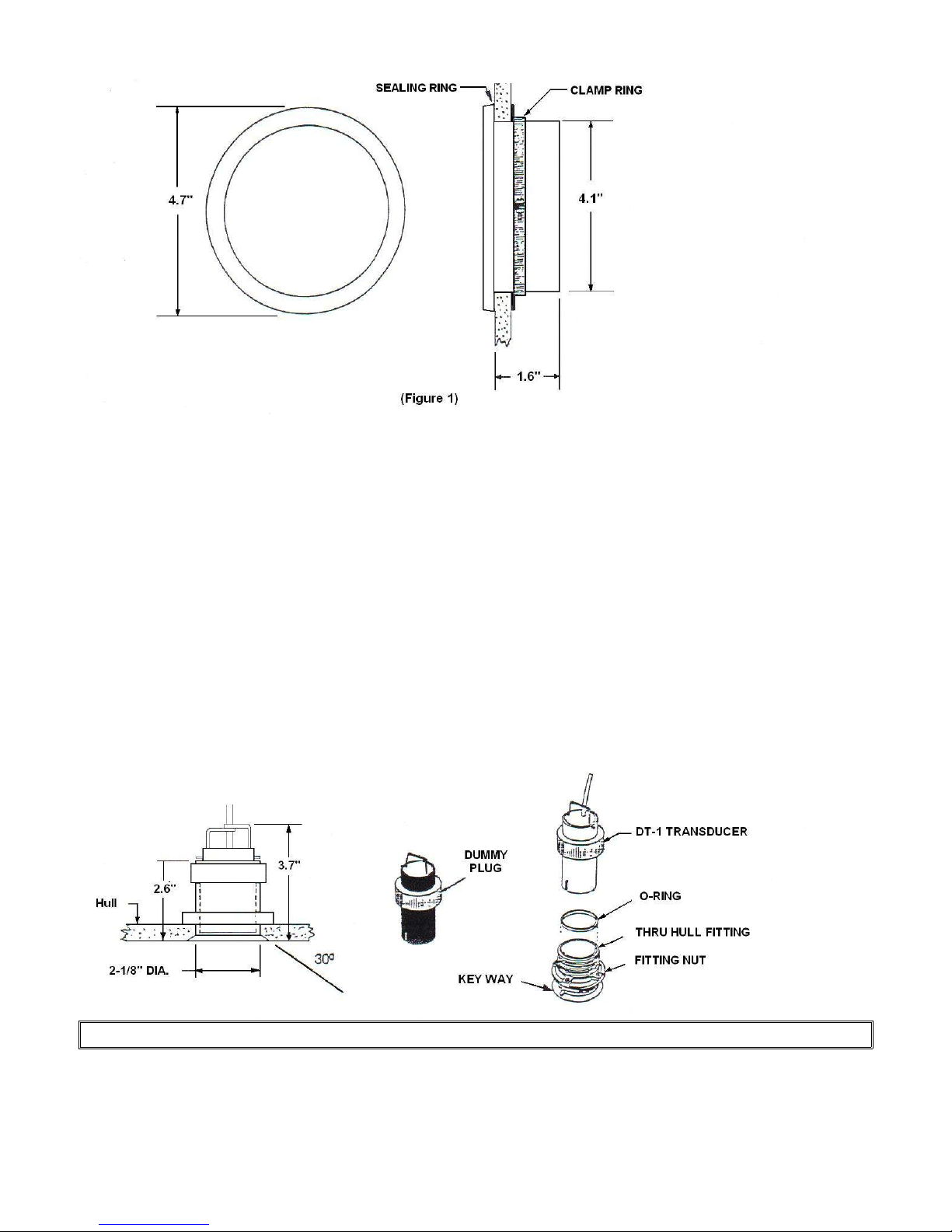
INSTALLING THE DISPLAY
1. Cut a 4- 1/16" (max 4- 1/8") diameter hole in the bulkhead or instrument panel where the
display unit is to be mounted (fig.1).
2. Be sure to remove all burrs and clean the face of the bulkhead or panel with detergent to
remove all traces of dirt, oils, fingerprints, etc...
3. Each display unit is furnished with an adhesive backed sealing ring to hold the unit fast in
place and creates a watertight seal. Please note that it is not recommended that the paper
backing be removed until the system is tested and finally calibrated. When ready for final
mounting simply remove the paper backing, position unit correctly and firmly press into place.
4. Install the RETAINING RING as shown and tighten with a blade type screwdriver.
NOTE: Maximum hull thickness for thru hull fitting is 1- 1/4”
(Figure2)

INSTALLATION TIPS FOR TRANSDUCERS
SAILBOATS:
The preferred position of the transducer is where water is diverging around the hull and is free
from turbulence and eddies. This is generally in the forward one- third of the hull in front of
the keel and approximately one foot off the centerline. Generally the knot meter transmitter
can be mounted on one side of the keel with the depth transducer in a similar position on the
opposite side of the keel. If due to access considerations, it is necessary to locate the depth
transducer and the knot meter transmitter on the same side on a fore and aft line, be sure to
locate the depth transducer forward of the knot meter transmitter so that the turbulence
created by the paddlewheel does not interfere with the depth sensor.
The depth transducer should be installed in a fairly flat area where the degree of angle does
not exceed 20 degrees (you can use fairing blocks to accomplish this). An alternate location is
along side the keel two feet away and ahead of amidships.
The thru hull fittings require a 2 1/8" hole with a 30 degree flange. SR Mariner provides a tool
(THT) that drills and flares this hole in one operation. If this tool is not available locally
contact the factory and arrangements can be made to rent one (the THT tool requires an 1/2"
drill motor).
NOTE: The thru hull fitting should already have an o- ring installed.
INSTALLING THE TRANSDUCER
THRU HULL:
Choose the location of the sensors and cut your holes for the thru hull fittings. File a notch
FACING FORWARD to seat the key way. The key way ensures proper orientation of the sensors
for use and/or maintenance. After proper fit is secured, place bedding compound around the
lip and body of the fitting where it will be in contact with the hull. Insert the thru hull fitting
and tighten the fitting nut by using a spanner wrench or tap with a small wooden block against
the nut to provide a snug fit. DO NOT OVER TIGHTEN!
CEMENTED TO HULL:
If your primary importance is for shallow water monitoring, the transducer may be cemented
to the hull thereby eliminating a need for a hole through the hull. The position selected must
not have air voids, balsa fillers, etc… It is best to choose a location and make a small putty
dam and fill it with water and put your transducer in it to see if a stable depth is indicated (the
boat should be afloat and the transducer face should be wetted before inserting into puddle).
At this point back off on the gain until reading becomes unstable to see how much reserve
gain is available. Compare this gain setting with the transducer hung overboard; this will give
an approximation of attenuation at the chosen location. If operation is suitable, clean the
surface of the transducer with lacquer thinner to remove the anti- fouling paint. Clean the hull
to remove grease and mold release. The transducer may now be cemented with epoxy or
fiberglass resin (stir the epoxy slowly to avoid air bubbles). THERE SHOULD BE NO AIR
BUBBLES IN THE ADHESIVE BOND.

FOLLOW THE MOUNTING INSTRUCTIONS FOR
DISPLAY AND TRANSDUCER BEFORE PROCEEDING:
1. Connect the transducer and power wires to the display unit as shown in figure 3.
2. If you choose to connect night lighting simply connect your 12 volt D.C. wire as indicated in
figure 3 and install a SPST switch on the positive (+) line to complete the circuit and activate
the lights.
3. To set alarm, turn the left knob on instrument to SET. Next, turn the right knob to desired
alarm setting. The visual alarm (and DA- 1, if installed) will be activated when depth is at or
below alarm setting.
(Figure 3)
CALIBRATION
GAIN:
The rear GAIN control is a manual override on the automatic gain control (AGC) and is used to
set the maximum gain. It usually is factory set to be fully clockwise (maximum gain) for the
greatest sensitivity, however sometimes turbulence, ignition or electrical disturbance, or
spurious reflections from the keel may make the readings unstable. If this occurs, turn the
GAIN control counter clockwise slightly until the readings stabilize.
SHALLOW GAIN:
When the transducer sends out its signal, it can receive a reflection from the keel, pilings or
other nearby objects before the reflection from the bottom. To eliminate the returns from
these unwanted signals, the SHALLOW GAIN must be adjusted. For best results start in 10- 15
feet of water and turn the SHALLOW GAIN clockwise until the readings are substantially less
than the actual depth. Now turn counter clockwise until the readings return to the actual
depth. Repeat this procedure while under way.
KEEL OFFSET:
The display can be adjusted to display depths from surface of the water to bottom, from the
keel to bottom, or transducer to bottom - the unit is factory set for transducer to bottom. If
you desire a different set up then measure the water depth with a lead line and adjust the
KEEL OFFSET clockwise for a lower reading (keel to bottom) or counter clockwise for a higher
reading (surface to bottom). Each indicator represents a 1 foot increment.

POWER CONSUMPTION
LIGHTS AMPS
OFF .020A
ON .175A
ACCESSORIES
ICW- 1 INSTRUMENT COVER
O- RING GASKET FOR THRU- HULL
DP- 1 DUMMY PLUG
CLP RNG CLAMP RING
MC-1 METER CASE FOR (YOUR MODEL NUMBER)
SEAL RING GASKET FOR INSTRUMENT GAUGE
TH- 1 THRU- HULL FITTING
DA- 1 AUDIBLE DEPTH ALARM
Made in the USA
 Loading...