

Page 1

SRM Training System
User Guide
Page 2

TABLE OF CONTENTS
INTRODUCTION 2
SRM POWERMETER
COMPONENTS 3
INSTALLATION OF POWERMETER AND CADENCE MAGNET 4
SRM WIRELESS ACCESSORIES
COMPONENTS 5
SRM POWERCONTROL 7
BUTTONS AND VIEWS 6
SLEEP, REAL-TIME, AVERAGE, MAXIMUM, TIME/DATE 7
PAIRING POWER, HEART RATE, SPEED, DUO-TRAP 8
ZERO-OFFSET AND ALTITUDE 9
SETUP MENU 10
CLEARING THE DISPLAY, BATTERY STATUS, TOTAL TRAINING, SOFTWARE VERSION 11
INTERVAL TRAINING 12
ANT+ COMPATIBILITY 13
SRM TRAINING SOFTWARE
DOWNLOADING SRMMAC, SRMWIN 14
SRMWIN, SETUP AND DOWNLOADING OF POWERCONTROL 15
SRMMAC, SETUP AND DOWNLOADING OF POWERCONTROL 16
CARING FOR THE SRM 17
SERVICING THE SRM 17
WARRANTY INFORMATION 17
Page 3

2
INTRODUCTION
Congratulations on your purchase of your SRM Training System!
At SRM, precision, quality, durability, and customer service are our core motivators.
We have set the standard for power measurement so you can be confident you are
receiving the highest quality system on the market. Every SRM Training System is
hand-built in the US and Germany and personally tested by our expert technicians.
SRM offers two types of purchase options. Customers may purchase the PowerMeter
Only or the complete SRM Training System.
SRM PowerMeter Only SRM Training System
SRM PowerMeter* • •
Cadence Magnet • •
SRM PowerControl 7
and SRM Software
•
Wireless Accessories •
3 Year Warranty • •
* Customer must provide cranks/chainrings for Cannondale and Specialized PowerMeters. Bottom brackets only come with FSA, Rotor 3D, Shimano XT.
Page 4
3
SRM POWERMETER
Components
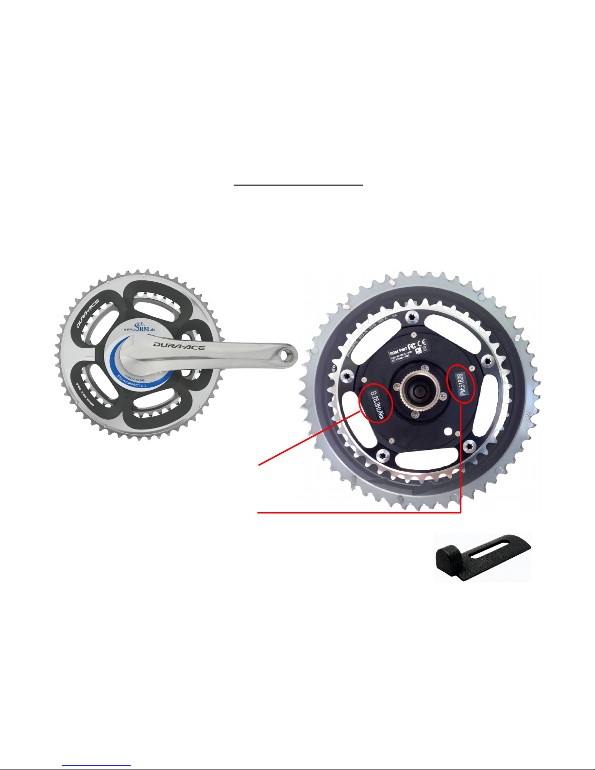
PowerMeter: The PowerMeter is the “spider” to which your right crank arm is attached.
Its serial number is a 6-digit number machined on the front or backside of the PowerMeter, close to the chainring bolts. PowerMeter slope can be found on the lid on the back of
your PowerMeter (e.g. 23.7 Hz/Nm).
Cadence Magnet: Every SRM PowerMeter comes with a cadence
magnet, which is required to turn the PowerMeter on and continuously transmit data. See pg. 7 for cadence magnet installation instructions.
PowerMeter Slope
Example: S: 26.3Hz/Nm
PowerMeter Serial Number
Example: PM: 51828
Page 5
4
SRM POWERMETER
Installation
PowerMeter: Install the PowerMeter according to the original crank manufacturer’s
instructions. Depending on the bike frame, you may need to purchase the correct bottom
bracket and/or adapters. It is recommended that you have the SRM PowerMeter installed
by a professional bike shop or service technician.
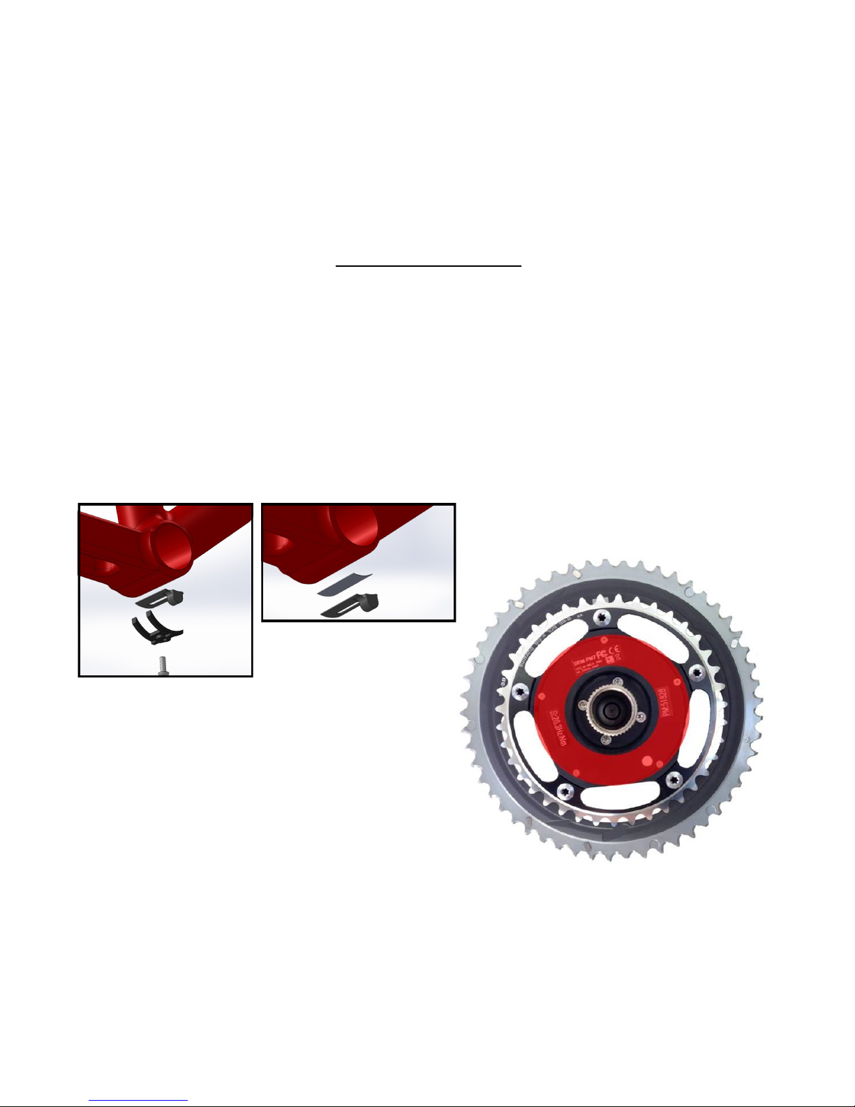
Cadence Magnet:
The cadence magnet may be mounted under the cable guide (A) or secured with industrial double-stick tape to the bottom bracket shell (B).
A B
Location:
The cadence magnet path is highlighted in
red. The magnet should be mounted 3-5mm
away from the inner lid and pass within the
highlighted area. The exact cadence magnet
path differs among PowerMeter models. Successful Pairing (pg. 11) and cadence indicate
correct magnet placement.
Page 6

5
SRM ACCESSORIES
Components
The SRM Training System is a complete and comprehensive package designed to optimize your training program. In addition to the SRM PowerMeter and PowerControl, the
SRM Training System includes the wireless accessories below.
1. Handlebar Mount: 31.8mm Round, 26.0mm Round, or Integrated Stem Mount
2. Speed Sensor: VDO Speed Pod (fork or chainstay mounted), or Suunto QuickRelease Skewer (front wheel only)
3. Suunto Heartrate Monitor
4. Mini-USB Download Cable (can be used to charge PC7 via computer)
5. Wall Charger (with international plug kit)
Page 7
6
SRM POWERCONTROL 7
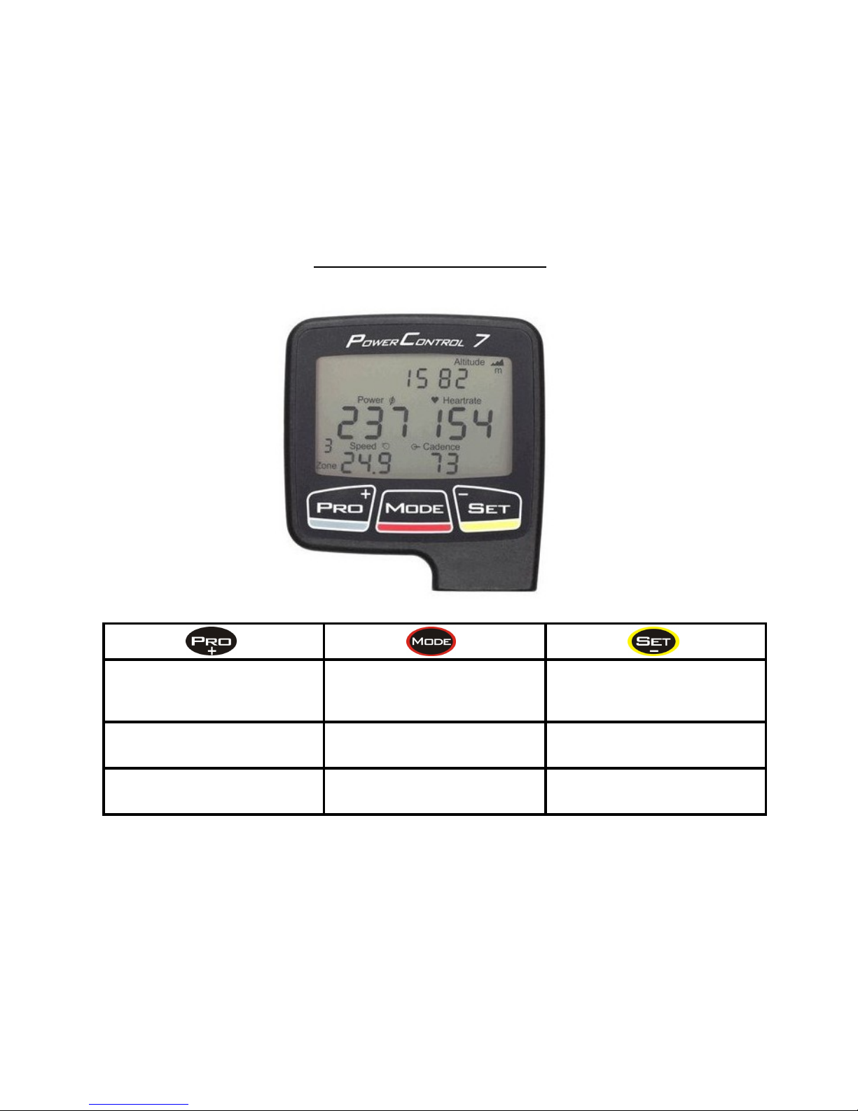
Buttons and Views
Click:
Go to training zones
”+” in setup mode
Click:
Awake from sleep mode
Change screen
Click:
Start/stop interval
”-” in setup mode
Hold 3 seconds:
Enter pairing mode
Hold 3 seconds:
Back to real-time screen
Hold 3 seconds:
Enter setup mode
Hold 5+ seconds:
Enter sleep mode
Page 8
7
SRM POWERCONTROL
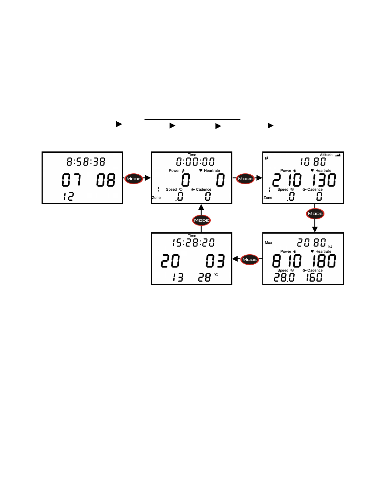
Sleep Mode Real-Time Average Maximum Time/Date
Time/Date/Sleep
Real-Time Average
Maximum Time/Date
The SRM PowerControl 7 has 4 main display screens which can be viewed easily during or
after a ride. Use the MODE button to scroll through the Real-Time, Average, Maximum,
and Time/Date screens.
Real-Time displays the current Power, Cadence, Speed, Heart Rate, and Training Zone.
The top line will alternate between time, altitude gained, and distance. You can adjust the
top line display settings in SRMWin or SRMMac under “PowerControl Setup.” (pg. 16)
Average screen displays the average Power, Speed, Cadence, and Heart Rate of the
ride.
Max screen displays the maximum Power, Speed, Cadence, Heart Rate, and total kilojoules for the ride.
Hold the MODE button for 5 seconds to put the PowerControl in Sleep Mode.
Page 9
8
SRM POWERCONTROL
Pairing/Synchronizing
Power Heartrate Speed Duo-Trap Speed Duo-Trap Speed/Cadence
Real-Time
Hold for 3
Seconds
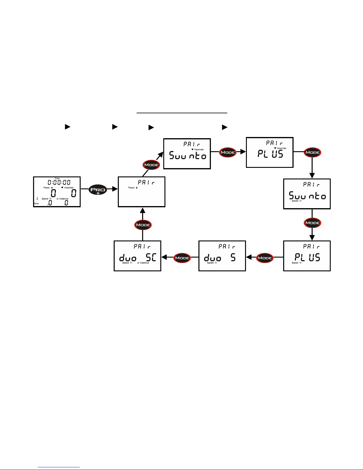
1. From the Real-Time Screen, hold PRO for 3 seconds to enter pairing mode where you
will synchronize the PowerControl with the PowerMeter, Speed Sensor, and Heart Rate
monitor. Scroll through the different wireless device options with the MODE button.
Device must be activated and transmitting by spinning crank or wheel before pairing.
2. Once you are on the screen for the device you would like to pair, press SET. An an-
tenna will begin blinking in the lower right corner. Once your device is detected,
“Found” will be flashing on the screen.
Power= SRM PowerMeter Speed Suunto= Suunto QR Front Wheel Skewer
Heartrate Suunto= Suunto Dual HR Strap Speed Plus= SRM VDO Speed Pod (fork or chainstay)
Heartrate Plus= Garmin HR Strap Speed DUO S= Duo-Trap Speed ONLY
Speed/Cadence DUO SC= Duo-Trap
Page 10
9
Setting the Zero-offset before every ride is recommended to ensure the most accurate data.
The Zero-offset can be compared to zeroing a bathroom scale before weighing yourself; the
scale must start at 0 to measure an accurate weight.
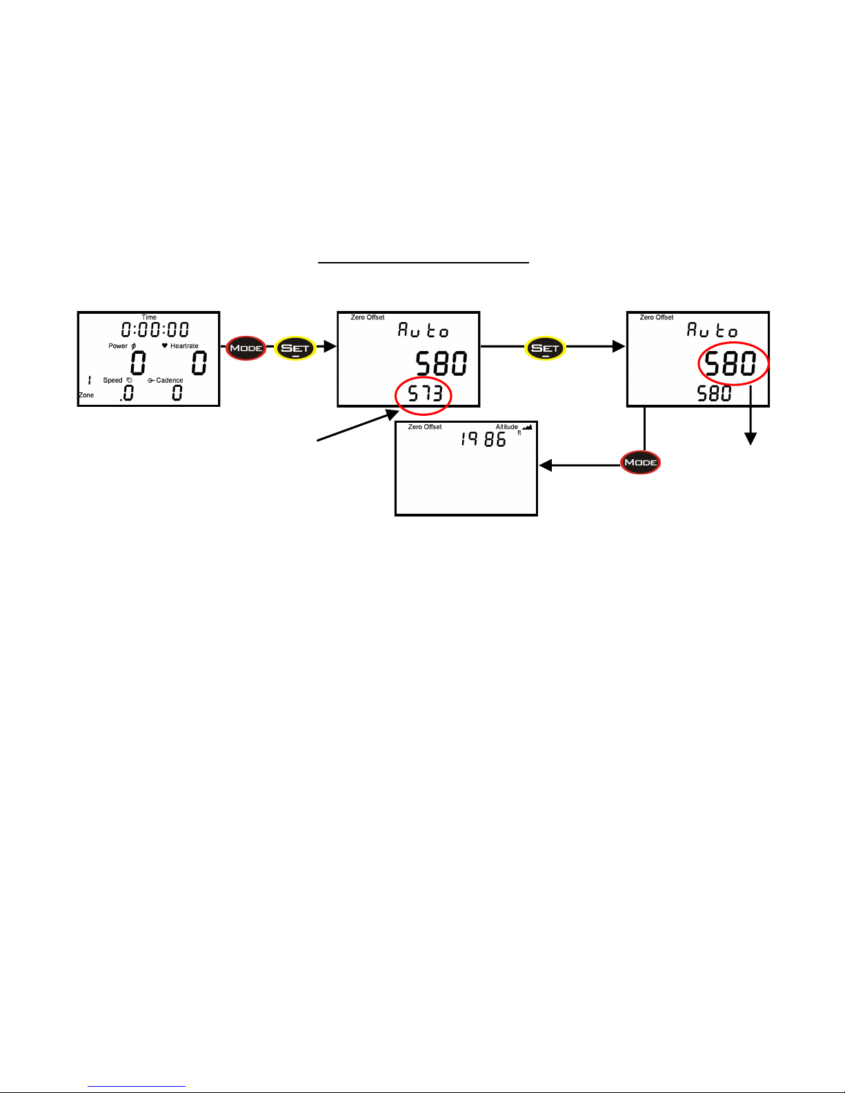
From the Real-Time screen press MODE and SET simultaneously to enter the Zero-offset
mode. You will see two numbers; the top number is the current offset of the PowerMeter
and the lower number shows the previously stored offset. Hit SET once and the lower number will update to store the current offset. You have successfully completed the Zero-offset.
The Zero-offset is affected by temperature and humidity and can change slightly from day
to day and during a ride. The SRM PowerMeter has the ability to automatically update the
Zero-offset to account for these changes. The “Auto” function is activated when the word
Auto appears in the Zero-offset screen, this is the default setting in the PowerControl. A
speed sensor must be installed and transmitting in order for the Auto Zero-offset to function.
Altitude can be adjusted from the Zero-offset screen by pressing MODE. Use the PRO and
SET button to view or adjust elevation.
SRM POWERCONTROL
Zero-offset and Altitude
Previously stored
zero-offset
Current
zero-offset
Simultaneously
Page 11

10
SRM POWERCONTROL
Setup Menu
Date/Time Slope Wheel Circumference Storage Interval Training Zones
The PowerControl setup menu allows you to easily view and change settings and is accessed through the Real-Time screen by holding SET for 3 seconds. Click the MODE button to scroll through the fields and use the PRO(+) and SET(-) button to increase or decrease numbers.
Time: Time of day, date, and year.
Slope: Indicates if the Auto Slope function is on and the paired PowerMeter’s slope.
Circ: Wheel circumference.
Store: Interval of storage can be set from 0.5 to 5.0 seconds. The total available memory in
hours is displayed at the bottom.
Zones: 5 training zones based on Power or Heart Rate can be customized.
tel: Telemetry mode is designed for human performance broadcast and does not affect data;
requires additional hardware sold separately.
Page 12
11
SRM POWERCONTROL
Clearing the Display, Battery Status, Total Training, Software Version
Simultaneously
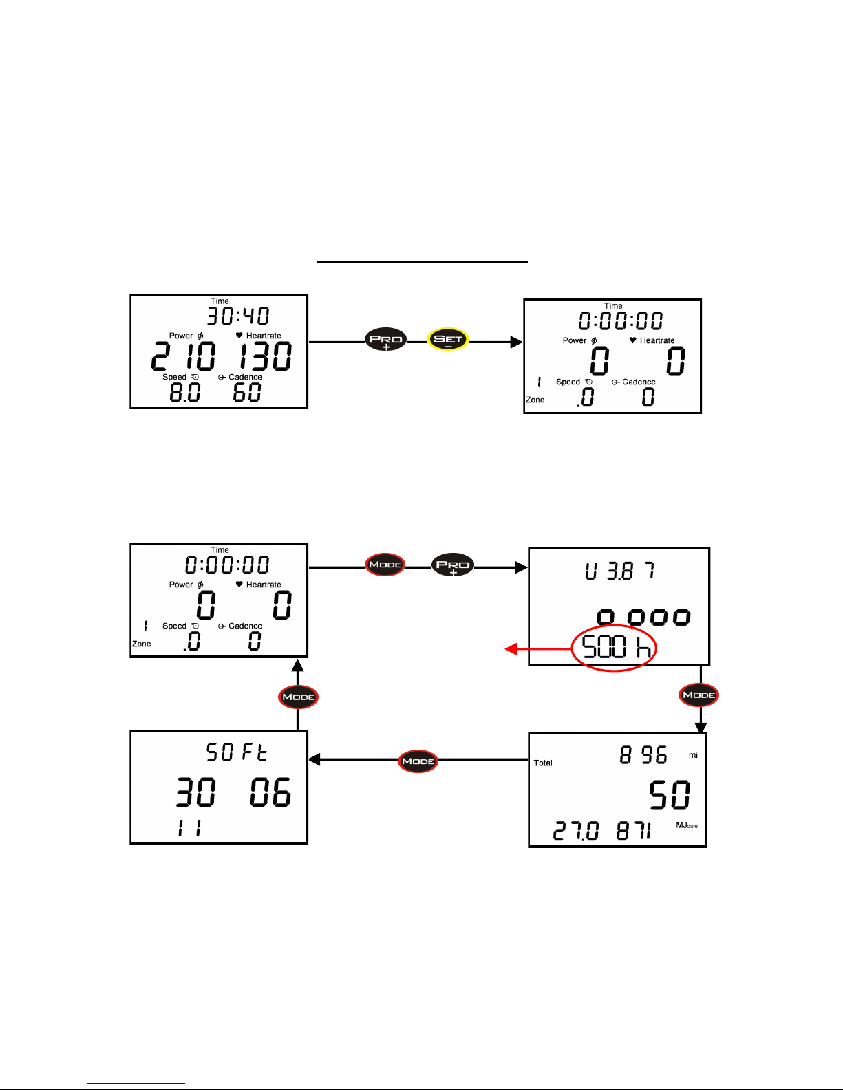
Clearing the Display: To clear previous data and start a new ride file begin in the Real-Time
screen and hold PRO and SET simultaneously. This will clear the display. Previous data will be
stored for future download. The Auto Start New Training function allows PC7 to automatically
start a new training after set amount of time. Activate and manage this feature in SRM Win
software.
Real-Time
PC and PM Battery Status
Software Version of PC
Total Distance, Total Training Hours,
Total Energy Expenditure
New: Hours
remaining on
PowerMeter
Page 13
12
SRM POWERCONTROL
Interval Training
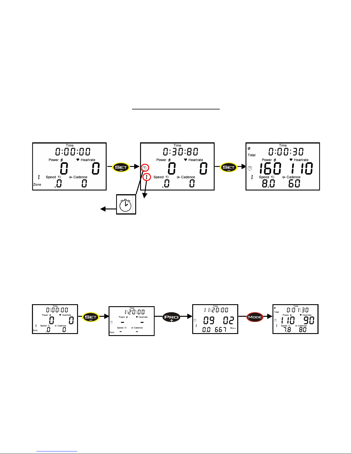
Review Interval Data : Press PRO to view time, date, and energy of past intervals. Press MODE to
scroll down through individual max and average screens for each interval (last to first interval). The
PowerControl 7 will display up to 20 intervals and can store unlimited intervals for download to training software.
Indicates Interval number
Real-Time
Flashing clock indicates
interval mode on
Screen displays total time/
altitude gained/distance for
the Interval and the average
Power, Heart Rate, Speed,
Cadence for Interval. This
screen stays up for 10 seconds.
Push SET to begin new Interval Push SET to end Interval
Real-Time
Interval Mode
Interval
Time/Date/Energy
Interval Review
Avg & Max
Page 14

13
ANT+ COMPATIBILITY
The SRM Wireless PowerMeter is ANT+ compatible. There are a number of ANT+ bike
computers on the market (e.g. Garmin) which will connect with the SRM PowerMeter;
however, SRM can not guarantee that data displayed on third party head units is accurate
to the standard of the SRM PowerControl.
Below is an example of how the Garmin device connects to a power meter.
Connecting a Garmin:
1. Menu, Settings, Bike Settings
2. ANT+ Power, check “PowerMeter yes”
3. Rescan
4. Spin cranks forward until it reads “PowerMeter present”
5. Calibrate, wait for it to read “Calibration success”
6. Sensor Details will show PowerMeter slope and serial number
Note: A combined speed/cadence sensor (e.g. Duo-Trap) must be turned off in order for
your ANT+ device to display Cadence and Power.
If you need assistance using a Garmin, visit www.garmin.com.
Page 15
14
SRM SOFTWARE
Installing SRMWin, SRMMac
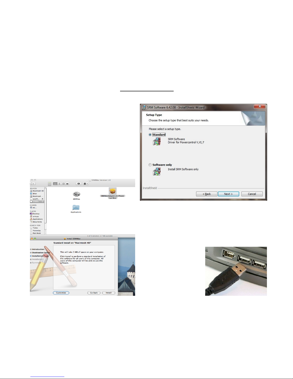
In order to view and analyze SRM training files,
you must have a software program that is
compatible. Every SRM Training System comes
with SRM Software (for Windows or Mac)
download free at www.srm.de. The SRM
Installer will offer the following choices for
Windows:
Standard: Will install the SRM Software with
drivers for PCV, VI, 7.
Software only: Will install SRM Software only.
This option must be chosen if you already have
a previous version of SRMWin installed.
On SRMMac Software, you must run the “SRMMacSetup”
in order to fully install the software on your computer.
Only then can you open the SRMMac. SRMMac software
is compatible with PowerControl VI and 7.
Note: If needed, PowerControl drivers are also available
for download at
www.srm.de.
Page 16
15
SRMWin SOFTWARE
PowerControl Setup, Battery Life, and Downloading Data
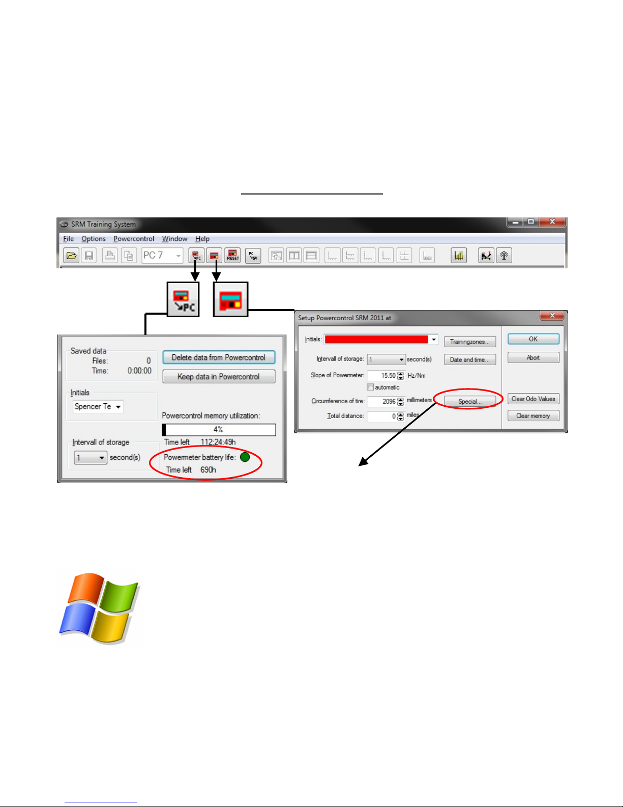
Setup of PowerControl: Enter your initials into highlighted bar. Download data from
PowerControl
Delete data from PowerControl to free up
more memory or keep the data in PowerControl for re-downloading on another computer.
View PowerControl memory storage and the
total hours used on the PowerMeter.
Click “Special…” to manage PowerControl Hardware
and Display settings.
Hardware Tab: PowerControl StandBy and Auto Zero
-offset options as well as wireless device settings.
Display Tab: Customize the data displayed during a
ride and select imperial vs metric units.
Page 17
16
SRMMac SOFTWARE
PowerControl Setup and Downloading Data
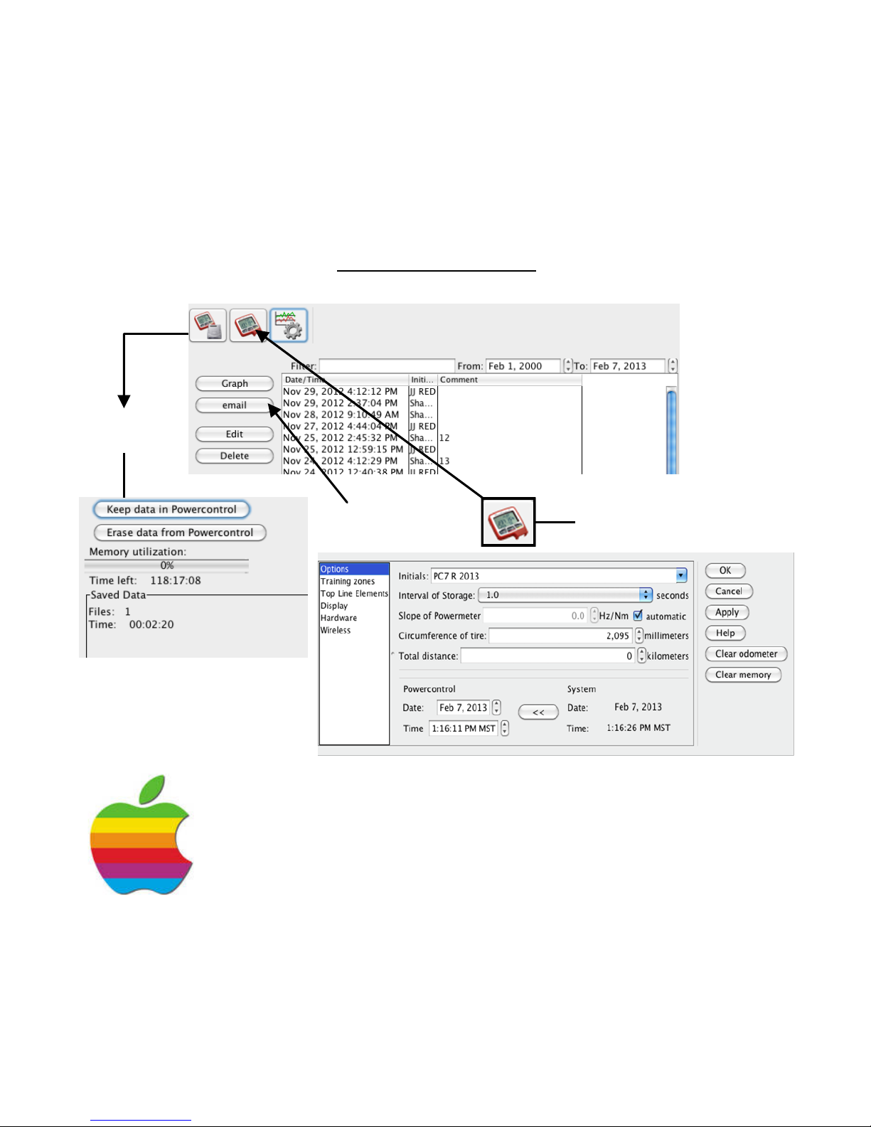
Download
Data
Delete data from PowerControl
to free up more memory or keep
the data in PowerControl for redownloading on another computer.
Email your SRM file to a
coach or friend
Setup of PowerControl
In Setup of PowerControl enter initials and manage personal settings
including hardware, display, and wireless options.
Page 18

17
CARING FOR THE SRM TRAINING SYSTEM
The SRM PowerMeter and PowerControl are waterproof; however, we DO NOT recommend using a pressure washer. When cleaning your PowerMeter or PowerControl, use a
cloth or rag with a mild detergent or soap. Solvents and degreasers can damage the
PowerMeter decal and PowerControl. Do not submerge or clean in a solvent tank. Do not
use any flammable substance.
SERVICING THE SRM TRAINING SYSTEM
In a great effort to improve customer experience, SRM features 1,900 hours of battery
life to every road PowerMeter. This is nearly 5x more than any other power meter on the
market today and equates to over 3 years of regular training for most users. There is a
PowerMeter battery counter in SRMWin software which will alert you as to when a factory
battery replacement is required (pg 16).
Standard SRM service includes battery change, recalibration, and waterproofing. A Service Order Form can be downloaded at www.srm.de and mailed to your SRM Service
Center with the unit.
WARRANTY INFORMATION
Complete and send in the provided warranty card to activate the warranty and register as
the owner of your new SRM Training System. All new SRM PowerMeters come with a 3 year limited warranty and is void in the case of damage due to crashes and damage due
to opening the PowerMeter and/or PowerControl outside of the SRM Service Center. If
you have questions regarding warranty, please contact your SRM Service Center.
Page 19

18
FCC COMPLIANCE DECLARATION
Regulatory Compliance FCC ID: WCS-PM7 IC: 7761A-PM7
Regulatory Compliance FCC ID: WCS-PC7 IC: 7761A-PC7
This device complies with part 15 of the FCC Rules, Industry Canada RSS-210, and ICES-003. Operation is subject to the following two conditions:
1. This device may not cause harmful interference, and
2. This device must accept any interference received, including interference that may cause undesired operation.
This equipment has been tested and found to comply with the limits for Class B digital device, pursuant to part 15 of the FCC rules. These limits are designed to provide reasonable protection against
harmful interference in a residential installation. This equipment generates, uses, and can radiate
radio frequency energy and may cause harmful interference to radio communications if not installed
and used in accordance with the instructions.
However, there is no guarantee that interference will not occur in a particular installation. If this
equipment does cause harmful interference to radio or television reception, which can be determined
by turning the equipment off and on, the user is encouraged to try and correct the interference by
one of the following measures:
Reorient or relocate the receiving antenna.
Increase the separation between the equipment and the receiver.
Connect the equipment into an outlet that is on a different circuit from unit.
Consult the dealer or an experienced radio/TV technician for help.
This product does not contain any user-serviceable parts. Repairs should only be made by an authorized SRM Service Center. Unauthorized repairs or modifications could result in permanent damage to
the equipment, and void your warranty and your authority to operate this device under Part 15 regulations.
Page 20

19
SRM Germany
Rudolf Schulten Str. 6
52428 Juelich
Germany
Tel: +49 2461 69123 0
Fax: +49 2461 69123 17
SRM USA
720 W Monument Street
Colorado Springs, CO 80904
United States
Tel: +1 719 266 4127
Fax: +1 719 266 4284
SRM Italia
Via della Rimembranza, 726
55100 Lucca
Italy
Tel: +39 0583 332036
Fax: +39 0583 331684
SRM Oceania
104 B Weston Road
St. Albans, Christchurch
8052 New Zealand
Tel: +64 3355 94 67
Fax: +64 3355 94 69
WWW.SRM.DE
 Loading...