

Page 1
SR SYSTEM-ELEKTRONIK GmbH | Eschachstr. 23| D-78078 Niedereschach | phone +49 77289268-0 | inf [email protected]
SRLine TFT-Monitors
USER MANUAL
Rev.: 05.04.2012
Copyright © 2010-12 SRLine
Reproduction of any kind as well as an excerpt requires the written permission of the company
SR Sytem-Elektronik GmbH.
Page 2

Page 2 SRLine monitors user manual
SR SYSTEM-ELEKTRONIK GmbH | Eschachstr. 23| D-78078 Niedereschach | phone +49 77289268-0 | inf [email protected]
PLEASE NOTE: In case of the release of a newer version this document will not be collected, though all
previous releases lose their validity.
Page 3

Page 3 SRLine monitors user manual
SR SYSTEM-ELEKTRONI K GmbH | Eschachstr. 23| D-78078 Niedereschach | phone +49 77289268-0 | inf [email protected]
Index
General ........................................................................................................ 5
Introduction .................................................................................................6
Definitions, abbreviations and reference documents ......................... 7
Definitions .................................................................................................................................7
Abbreviations ..........................................................................................................................7
Safety instructions .......................................................................................8
Putting the TFT-Monitor into service .........................................................9
Unpacking equipment ..........................................................................................................9
Installing the unit .....................................................................................................................9
Information on compliance with the EMC directive .....................................................10
(CE mark) ...............................................................................................................................10
Model variants ..........................................................................................11
VESA-DPMS (Behaviour without video signal) .....................................11
Auto Signal Detection .........................................................................................................12
Features ..................................................................................................................................12
VESA mount (if available) ...................................................................................................12
Environmental Conditions ...................................................................................................12
OSD Menu-Functions................................................................................13
Menu DISPLAY .......................................................................................................................13
Hotkeys ...................................................................................................................................13
OSD Status (external LED's) .................................................................................................14
OSD Menu-Overview ............................................................................... 15
Menu INPUT ............................................................................................................................16
Menu Contrast / Brightness.................................................................................................16
Menu Color ............................................................................................................................17
Menu Image ..........................................................................................................................17
Menu Tools .............................................................................................................................18
Menu Language ...................................................................................................................18
Operation and Repair .............................................................................19
EMC .........................................................................................................................................20
Electrostatically sensitive components ............................................................................20
Cleaning ....................................................................................................21
EMC and Safety Equipment ...............................................................................................23
Attachment ...............................................................................................24
Pin assignment VGA.............................................................................................................24
Page 4
Page 4 SRLine monitors user manual
SR SYSTEM-ELEKTRONIK GmbH | Eschachstr. 23| D-78078 Niedereschach | phone +49 77289268-0 | inf [email protected]
DVI ...........................................................................................................................................25
AC-supply unit .......................................................................................................................26
DC-connector 12 / 24 V ......................................................................................................26
Ground bolt ...........................................................................................................................26
Correction Overview
Amendment
to Chapter/
Page output
Issue date
Reason for change
09.11.2009
preperation of this document, Firmware 1027
17
22.12.2009
Change DOS/Graphic (720/640 x400 x350) see
("Advanced" -> "640-720") Firmware 1032
17
23.02.2010
Firmware update 1037:
extended power down to 20 sec
Autoscan manual or Automode
(shown as "Fixed")
RGB changed to VGA
19.04.2010
Alternating video controlle eM with different OSD
05.04.2012
corrections
Page 5

Page 5 SRLine monitors user manual
SR SYSTEM-ELEKTRONI K GmbH | Eschachstr. 23| D-78078 Niedereschach | phone +49 77289268-0 | inf [email protected]
General
This manual will help you in installation, assembly and use of the flat
panel. Please read the entire manual once, since information
relating to several chapters will only be given once. Keep this
manual. Follow all instuctions and warnings noted on the product
itself, Do not use liquid or caustic cleaning agents, Use a moist, lintfree cloth for cleaning. Never operate the unit near water.
Never place the unit on an unstable surface. All the slots and
openings on the underside and back of the device are used for
ventilation, to protect it from overheating adequately. These vents
must never be covered. The device shall never be placed near or
on a radiator or any other source of heat. The unit always has to be
connected to a power supply according to the badge on the
back side of the case. Do not insert objects through the vents. Do
not spill liquids on the device. Leave all repairs to qualified
technical personnel.
Do not expose the device to direct sunlight.
SR System-Elektronik GmbH does neither provide a guarantee nor
take legal responsibility or any other liability for any consequences
resulting from incorrect informations. Changes in the scope of
performance and technical data can be made at any time and
without special notice.
Page 6

Page 6 SRLine monitors user manual
SR SYSTEM-ELEKTRONIK GmbH | Eschachstr. 23| D-78078 Niedereschach | phone +49 77289268-0 | inf [email protected]
Introduction
This LCD display acts as a video-compatible colour display.
The monitor serves for operating digital TFT displays with resolutions
of 460 x 480 up to 1920 dots x 1080 directly with the standard video
signals from PC’s and workstations.
A dedicated graphics card is not required. The image signal is fed
through a standard monitor cable.
Video modes with a lower resolution than the TFT resolution can be
expanded freely and so use the full display area of the device. By
using high qualitiy filtering the image content remains unchanged.
Since the video signals from Pc’s and workstations are no subjects
to standardization in timing, the image position on specific variants
are adjusted in all parameters. All necessary settings are made via
an easy-to-use OSM-Menu (On-Screen Manager) and only have to
be chosen once, the selected parameters are saved.
The monitor is powered through the integrated wide-range power
supply or via an external power source. Any other voltages
necessary for the operation of the board and display are
generated on board.
The TFT screen boasts the following characteristics:
solid, industry-adequate construction
equiped with touchscreen optionally
EMC-compliant construction for increased interference
immunity and reduced interference radiation, CE Marking
and Declaration of Conformity for tested variants.
compatible with industrial standard.
Page 7
Page 7 SRLine monitors user manual
SR SYSTEM-ELEKTRONI K GmbH | Eschachstr. 23| D-78078 Niedereschach | phone +49 77289268-0 | inf [email protected]
Definitions, abbreviations and reference documents
Definitions
Abbreviations
OSD On Screen Display
MHz Number of oscillation processes in millions of cycles per
seconds
KHz Numbers of oscillation processes in thousands of cycles per
seconds
Hz Number of oscillations processes in cycles per second
H-Sync Displays the beginning of the broadcast of a new line.
Serves synchronization between a picture source and a
receiver.
V-Sync Displays the beginning of the broadcast of a new
picture. Serves synchronization between a picture
source an a receiver.
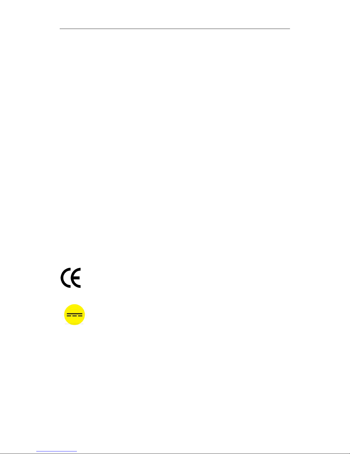
European Union Declaration of Conformity
Direct current DC
~ Alternating current AC
Page 8

Page 8 SRLine monitors user manual
SR SYSTEM-ELEKTRONIK GmbH | Eschachstr. 23| D-78078 Niedereschach | phone +49 77289268-0 | inf [email protected]
Safety instructions
The TFT monitor is designed for use in industrial and commercial
sectors. The one installing the device is responsible for safety and
compliance with occupational safety and accident prevention
regulations as well as any other statutory regulations.
Installation, setup and repair work must therefore be performed
by qualified personnel only. In doing so, the following safety
instructions have to be followed by all means:
By opening the backside of the panel, live parts can be
exposed. Therefore the monitor unit has to be turned off and
disconnected from the power grid through appropriate
measures first.
If operating the opened device is inevitable in line with set-up
and repairs, use particular caution. No modifications must be
made in this situation. Thus causing short-circuits resulting in
damage to various components cannot be excluded.
For manufacturing reasons, potruding edges and surfaces on
ircuit boards and sheet metal parts cannot be excluded.
Please handle with care to avoid injury.
When opening the unit, make sure that no electrically
conductive foreign objects, such as cuttings and screws, can
enter the unit, as this may cause short-circuits resulting in
serious consequences.
The torque of the fastening screws on LCD panels should
never exceed 0.39 Nm.
For cleaning the surface of the LCD panel use a soft, dry cloth
and do not use any chemical cleaning agents!
Page 9
Page 9 SRLine monitors user manual
SR SYSTEM-ELEKTRONI K GmbH | Eschachstr. 23| D-78078 Niedereschach | phone +49 77289268-0 | inf [email protected]
Putting the TFT-Monitor into service
Unpacking equipment
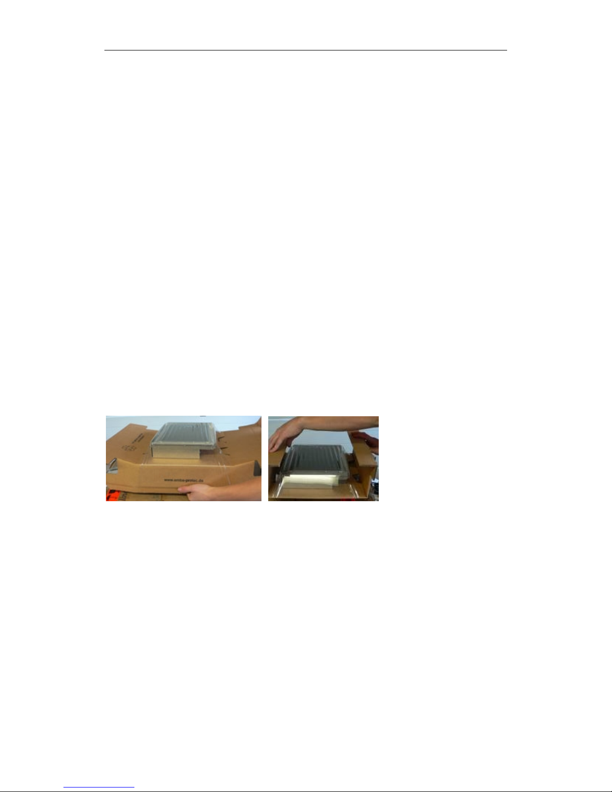
The TFT monitor is shipped in a sturdy cardboard box. The monitor is
fixed by a swing-foil and secured against damage during transport.
Keep all the parts at first to have a suitable transport packaging in
case of a necessary return.
Check the TFT monitor and the included accessories for shipping
damage. If there is noticeable damage to the device, it must not
be put into service because the security could be compromised.
Please contact the sender immediately.
Check the package using the delivery note.
Installing the unit
The TFT monitor must not be exposed to excessive cold, heat,
moisture or dirt. The ambient conditions given in the “Technical
data” must be met to maintian operational safety.
Before fixing the unit to a VESA mount check if the permissible
maximum weight for the bracket indicated by the manufacturer is
observed.
When mountig the device take care that adequate ventilation of
the equipment unit is guaranteed.
Also, remember that the temperature in a closed housing may be
much higher than the outside temperature. The termal situation
can be improved by appropriate arrangement of the installations
as well as forced ventilation. Make sure the specified temperature
limits are never exceeded when the unit installed.
Page 10

Page 10 SRLine monitors user manual
SR SYSTEM-ELEKTRONIK GmbH | Eschachstr. 23| D-78078 Niedereschach | phone +49 77289268-0 | inf [email protected]
Make sure there is enough space for the connections and no sharp
edges or corners protrude in that area. This may cause damage to
the cable connections and result in a loss of function and
performance.
Information on compliance with the EMC directive
(CE mark)
Within the EU, their are laws regarding the observance of uniform
limits concerning interference radiation and interference immunitiy.
The TFT monitor is designed to comply with these limits. It is therefore
equipped with the CE mark and comes with a certificate of
conformity. Outside the EU, the relevant national regulations have
to be observed.
Devices to be connected to the TFT monitor also have to comply
with the regulatory limits. Only this will ensure that the entire
installation complies with the statutory requirements. Make sure all
devices are equipped with an appropriate mark or a
manufacturer´s declaration.
The connection to the connected devices must be provided via
shielded cables. Cables with foil shields are less suitable than
cables with braided shields and a high degree of coverage. The
connector housing must be round to have connection to the cable
screen.
Page 11
Page 11 SRLine monitors user manual
SR SYSTEM-ELEKTRONI K GmbH | Eschachstr. 23| D-78078 Niedereschach | phone +49 77289268-0 | inf [email protected]
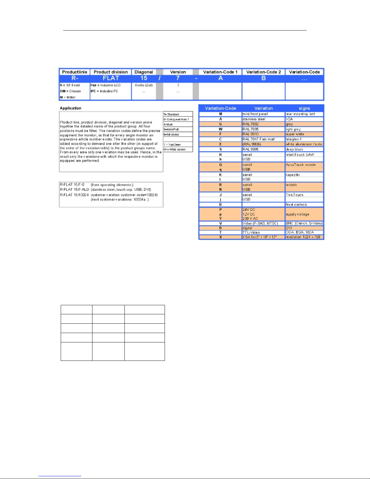
Model variants
VESA-DPMS (Beha vio ur without video signal)
The monitor indicates a missing video signal when turned on via an
OSD message (OSM menu, no Hsync). The LED of the OSD will
change to red or flash. After a while,the flashing disappears or
becomes dark and the monitor goes off. Wakeup: 6s.
HSYNC
VSYNV
Mode
ONONNormal
OFF
ON
Standby
ON
OFF
Suspend
OFF
OFF
Power
Off
Page 12

Page 12 SRLine monitors user manual
SR SYSTEM-ELEKTRONIK GmbH | Eschachstr. 23| D-78078 Niedereschach | phone +49 77289268-0 | inf [email protected]
Auto Signal Detection
This feature automatically detects the connected video input
signal. The monitor has a VGA-entrance/DVI and optional
video//Comp. Sync entrance. The controller starts with VGA, then
DVI, Video (CVBS) video (SVideo). If the signals are active later,
then the port scan may be within the search string. There is no
priority specified here, the first signal detected remains until it
becomes inactive. Until then there will be no port scan. If no signal
is connected or the video signal is lost (disconnected), the monitor
acts as described in VESA DPM S. This mode can only be restored
by switching on-off. Unless the power-suspend-mode was chosen
the last detected video source returns when connected again
(picture reappears).
Features
PC signals from 640x480 bis 1920x1080 (depending on the LCDscreen) with 60 Hz V-Sync are supported.
DOS, VGA, SVGA, XGA, WXGA, SXGA,SXGA+
H-Sync: 30 KHz ~ 80 kHz
V Sync: 56 Hz~ 75 Hz
VESA mount (if available)
Mounting screws M4 x 75 mm (length = max. 10 mm!);
M8 for bigger devices.
Environmental Conditions
Operating temperature: 0 ° to +50 ° C
Storage temperature: -20 ° to +60 ° C
Humidity: 85% (no condensation)
Page 13
Page 13 SRLine monitors user manual
SR SYSTEM-ELEKTRONI K GmbH | Eschachstr. 23| D-78078 Niedereschach | phone +49 77289268-0 | inf [email protected]
OSD Menu-Functions
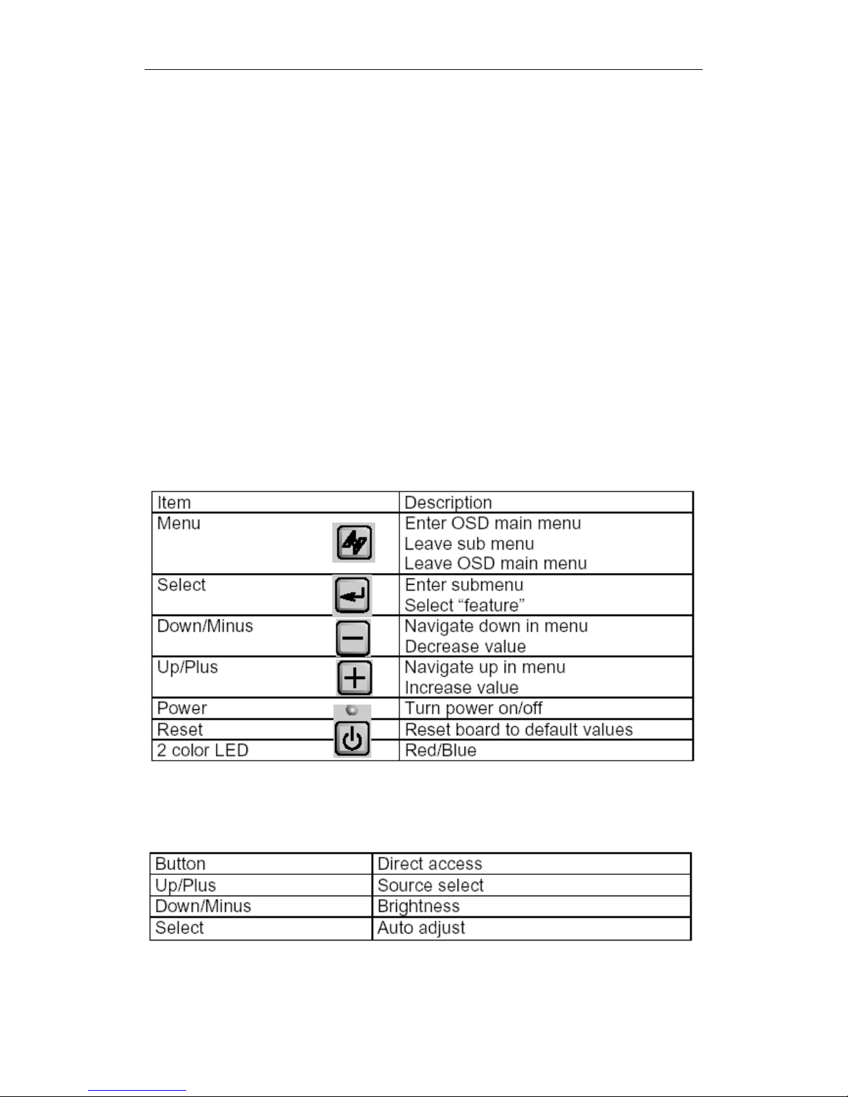
You will see a menu where you can choose between display usermodes and picture.
Select your desired setting by pushing the buttons “Up” or “Down”,
reach the selected submenu by pressing “Enter”, pushing the “Exit”
or the “Menu” button turns off the OSD, or a level up.
In addition, the main menu, the current line and frame frequency,
and if present, displays the stored user mode. If, instead of the line
or frame rate no Hsync or Vsync no display, no video signal is
present. In this case, the connection should be checked for the
graphics card.
Menu DISPLAY
Hotkeys
(Save please confirm)
Page 14
Page 14 SRLine monitors user manual
SR SYSTEM-ELEKTRONIK GmbH | Eschachstr. 23| D-78078 Niedereschach | phone +49 77289268-0 | inf [email protected]
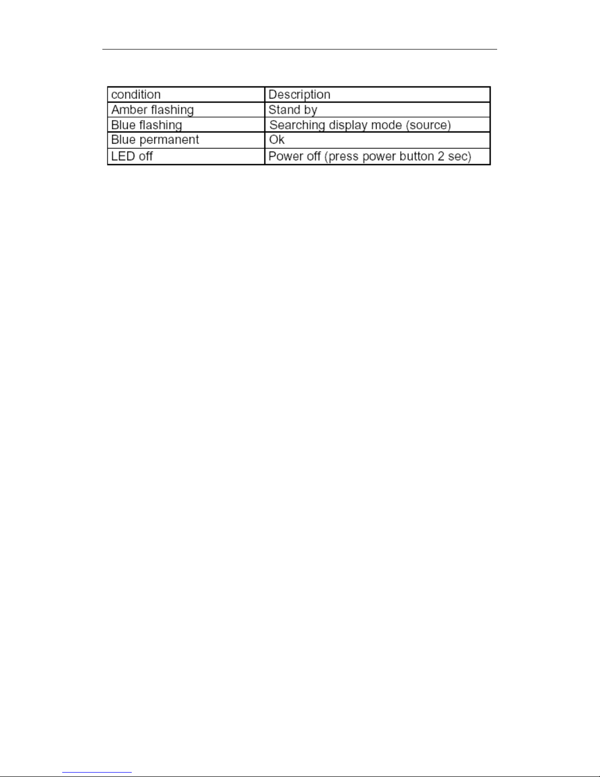
OSD Status (external LED's)
Page 15
Page 15 SRLine monitors user manual
SR SYSTEM-ELEKTRONI K GmbH | Eschachstr. 23| D-78078 Niedereschach | phone +49 77289268-0 | inf [email protected]
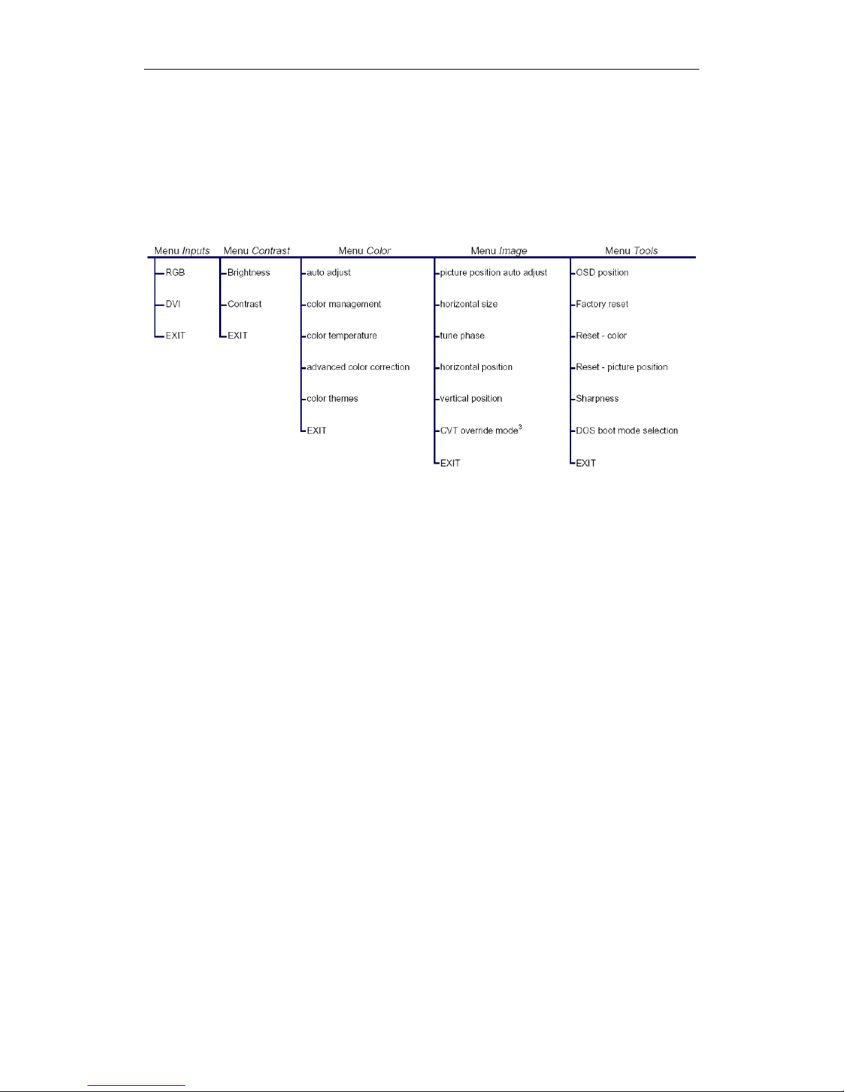
OSD Menu-Overview
To activate OSD press key „Menu“
Page 16
Page 16 SRLine monitors user manual
SR SYSTEM-ELEKTRONIK GmbH | Eschachstr. 23| D-78078 Niedereschach | phone +49 77289268-0 | inf [email protected]
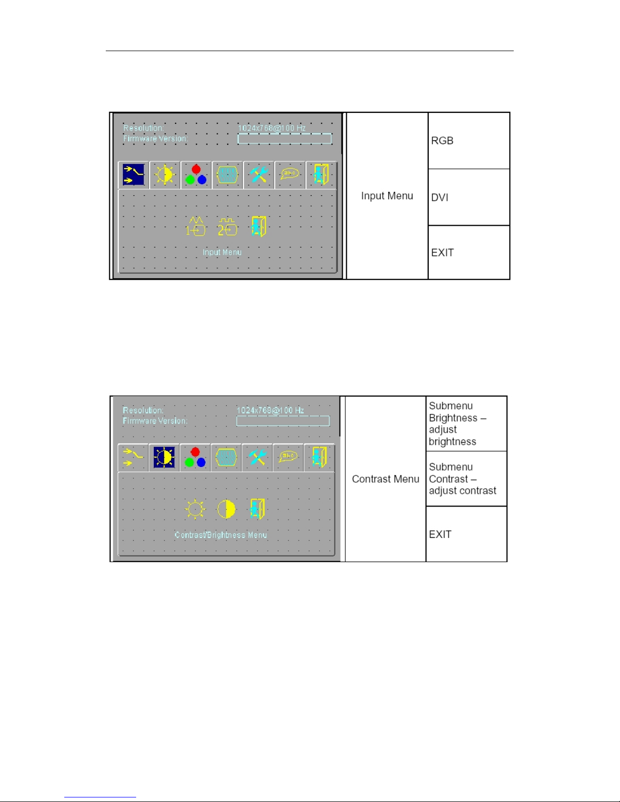
Menu INPUT
Menu Contrast / Brightness
Page 17
Page 17 SRLine monitors user manual
SR SYSTEM-ELEKTRONI K GmbH | Eschachstr. 23| D-78078 Niedereschach | phone +49 77289268-0 | inf [email protected]
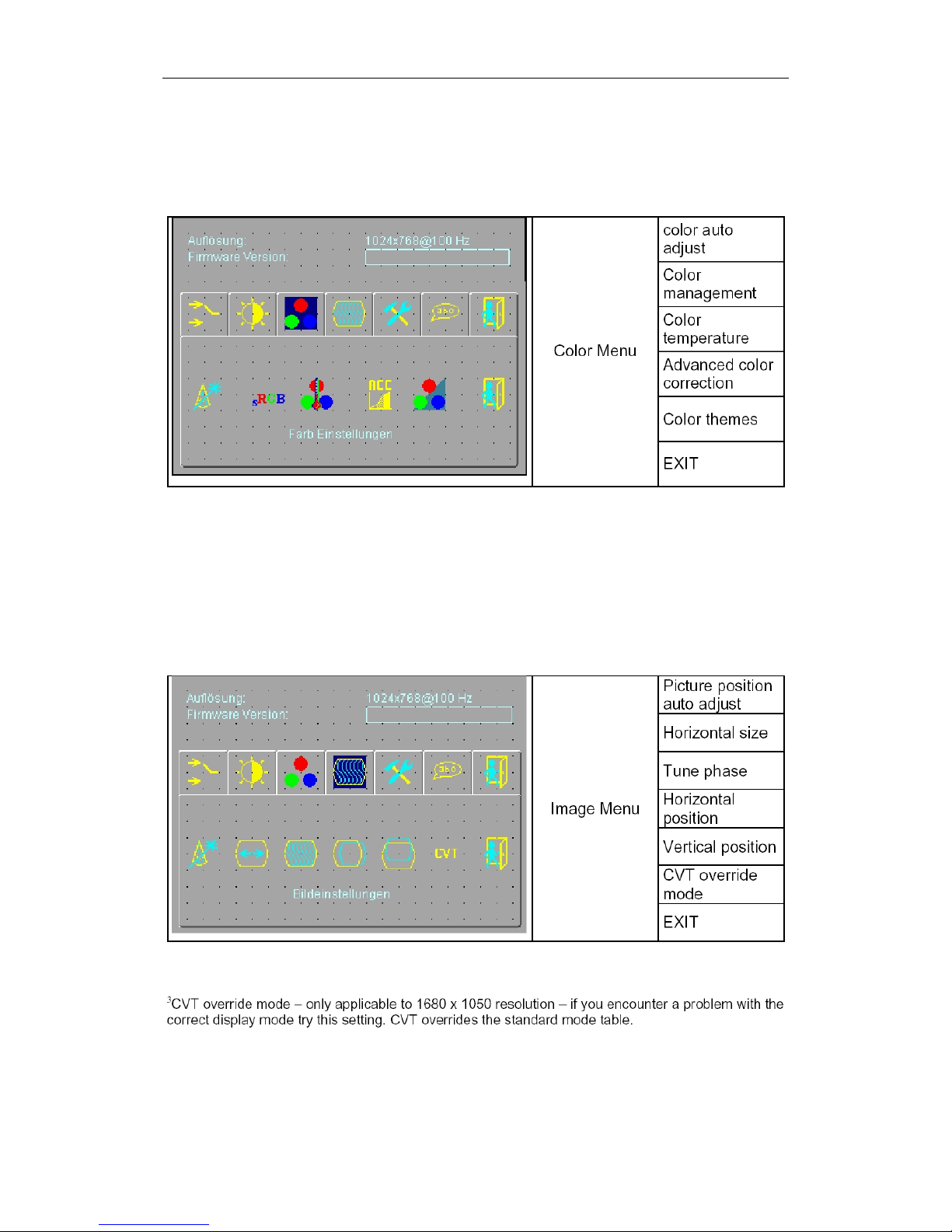
Menu Color
Menu Image
Page 18
Page 18 SRLine monitors user manual
SR SYSTEM-ELEKTRONIK GmbH | Eschachstr. 23| D-78078 Niedereschach | phone +49 77289268-0 | inf [email protected]
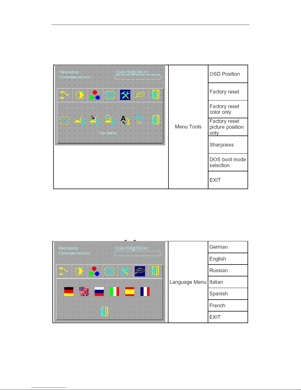
Menu Tools
Menu Language
Page 19

Page 19 SRLine monitors user manual
SR SYSTEM-ELEKTRONI K GmbH | Eschachstr. 23| D-78078 Niedereschach | phone +49 77289268-0 | inf [email protected]
Operation and Repair
Dg a freeze-frame for a longer period may cause image-
sticking-problems (see our notes in the support area on
our website in FAQ)
Before opening the device has to be switched off and
disconnected from the supply voltage.
Opening the device must be performed by authorized
personnel only!
Note that even after switching off the supply voltage or
pulling the plug high residual stresses may remain in the
device. Accidental contact with charged parts and
contacts may cause electrical shock and damage to the
device.
Do not insert any objects into the device. Foreign objects
of any kind inserted through the housing, can lead to
operational hazards and cause damage to equipment
and persons.
Do not spill any liquids into the interior. Should this happen
anyhow, immediately unplug the unit from the power
supply. Continued operation poses a fire hazard.
Install extensions compatible to your system only. Other
extensions can damage the device or change the EMC
behavior.
Important:
Subsequent installation of additional components or other
modifications to the device lead to invalidity of the
declaration of confimity for CE marking and the operator is
responsible for any occuring problems.
Immediately stop operating the device if you notice
anything abnormal, such as smoke, noise or smell. Unplug
the power cord and clarify the cause of malfunction
before operating the device again.
Page 20

Page 20 SRLine monitors user manual
SR SYSTEM-ELEKTRONIK GmbH | Eschachstr. 23| D-78078 Niedereschach | phone +49 77289268-0 | inf [email protected]
EMC
This is a class A device (industrial use). It may cause radio
interference in housing areas. In this case, the operator
might be charged to take adequate measures and be
held responsible for it.
This device serves as an installation component in an
industrial application. The operator of the entire system is
encouraged to maintain electromagnetic compatibility in
accordance with the EMC Act.
Electrostatically sensitive components
Electronic components can be damaged or destroyed by
electrostatic discharges. This doesn’t have cause a
breakdown of the module, it may also result in malfunctions!
The following directions must therefore be followed strictly:
Before working on an opened device a potenial charge of
the body has to be unloaded by touching the grounded
housing parts.
The same applies to (insulated) tools to be used, of course.
They also have to be discharged by touching a grounded
object.
If you remove or add modules from the system, the device
has to be switched off or disconnected from the power
supply every time.
You should always touch modules on the edge only.
Touching the conductors and connector pins has to be
avoided by any means.
Page 21

Page 21 SRLine monitors user manual
SR SYSTEM-ELEKTRONI K GmbH | Eschachstr. 23| D-78078 Niedereschach | phone +49 77289268-0 | inf [email protected]
Cleaning
Disconnect the device from the supply voltage before
cleaning. A dry cloth is sufficent for cleaning regularly. In
case of stronger contamination, the main unit can be
cleaned with a damp cloth and mild detergent (for CRT´s
only). No liquid must reach the inside of the case (open
device).
The use of scouring powder and dissolving detergent is
strictly forbidden.
The interior must be cleaned by the service technican
only.
Before getting the device into service it has to be
completely dry (short-circuit, fire hazard).
Since the surfaces of LCD´s ary very soft and easily
scratched, please use a soft dry cloth ofr cleaning and do
not use chemical cleaning agents.
The torque of the fixing screw on LCD panels should never
exceed 0:39 Nm.
Please never expose the surface of a LCD to shock or
friction as it could result in damage or scratch marks left on
the surface.
Page 22
Page 22 SRLine monitors user manual
SR SYSTEM-ELEKTRONIK GmbH | Eschachstr. 23| D-78078 Niedereschach | phone +49 77289268-0 | inf [email protected]
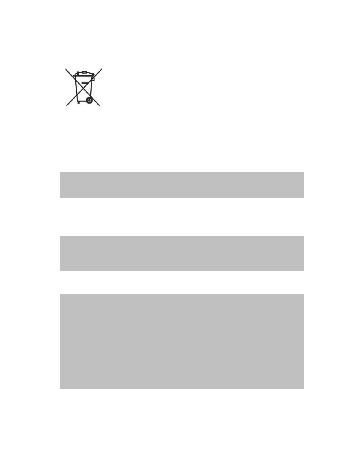
Proper disposal of the product (electronic garbage) only from Europe
apply in the countries of the European union and other European countries with separate
collection system.
The labeling on the product or on the accompanying literature indicates that it may not be
disposed to regular domestic waste after its lifespawn. Please dispose this device separated from
other wastes to prevent harming the environment and human health from uncontrolled waste
disposal. Recycle this device to assist the sustainable reuse of material resources.
Private users should contact the dealer where the product was bought or the competent
authorities in order to get to know how to recycle this decive in an environmentally friendly way.
Commercial users should contact their suppliers and consult the conditions of the sale agreement. This product must
not be disposed together with other commercial waste
DANGER OF EXPLOSION
The flat screen is not intended for use in hazardous areas.
ATTENTION: Equipment damage
The flat monitor has to be mounted torsion-free. This also applies to
the mounting brackets.
During installation and operation no pressure must be put on the
LCD panel. This is achieved through an appropriate mounting
device.
So-called OEM Monitors (OM-FLAT) have to be mounted in a way
so there is no pressure put on the LCD panel even after the
assembly. The glued rubber strip on special variants may therefore
not be compressed more than 0,2 mm.
The regular mounting position is vertical. A maximum tilt angle of
45° must not be exceeded.
Page 23
Page 23 SRLine monitors user manual
SR SYSTEM-ELEKTRONI K GmbH | Eschachstr. 23| D-78078 Niedereschach | phone +49 77289268-0 | inf [email protected]
EMC and Safety Equipment
Complicance with standards and guidelines
Certification that the industrial monitors developed to meet the following guidelines that
were adopted by the Council of the European Community, manufactured and tested
were:
2004/08/EC Electromagnetic Compatibility
EN 61000-6-3 EMC - Emission (Residential)
- EN 55022 B Interference voltage (150kHz - 30Mhz)
- EN 55022 B Radiated field (30MHz - 1Ghz)
EN 61000-6-2 EMC-immunity (industrial area)
- EN 61000-4-2 ESD / Electrostatic Discharge
- EN 61000-4-3 HF-field [ 80 - 2500Mhz]
- EN 61000-4-4 Burst / fast transients
- EN 61000-4-5 Surge / powerful transients
- EN 61000-4-6 conducted RF-Field / circuit bound HF-field
- EN 61000-4-11 Power variations / Net equalization
EMC tests were performed with standard cables with line lengths up to 2.5 meters.
Longer cables are used, then any further tests are required
to demonstrate compliance with the EMC directive.
RF radiation from 1000 to 2500 MHz, 80% AM 1k Hz, 10 V / m verified.
2.5 GHz to 2.7 GHz, 80% AM with 1 kHz and 1 V / m is considered.
93/68/EWG (CE-marking)
2006/95/EC Low Voltage Directive
EN 60950 Safety
Only device matching the EN Standard 60950 may be connected to the existing
interfaces. It is important to watch for "safe electrical isolation" to all the other tools /
data buses.
Page 24
Page 24 SRLine monitors user manual
SR SYSTEM-ELEKTRONIK GmbH | Eschachstr. 23| D-78078 Niedereschach | phone +49 77289268-0 | inf [email protected]
Attachment
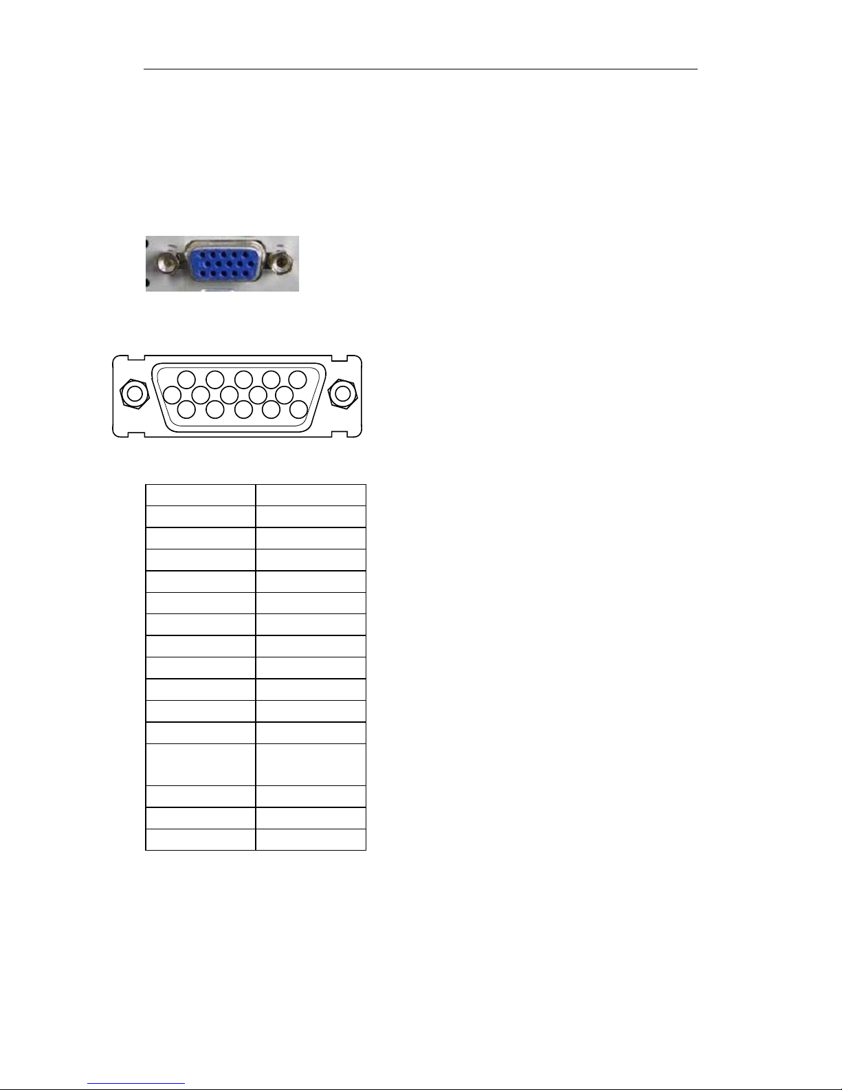
Pin assignment VGA
15-pole HD-Sub Mini DIN
Pin
Signal
1
Red
2
Green
3
Blue
4
GND
5
GND
6
GND
7
GND
8
GND
9
NC
10
GND
11
Nc
12
DDC Data /
SDA
13
H-SYNC
14
V-SYNC
15
DDC Clock
54321
6 7 8 9 10
1514131211
Page 25
Page 25 SRLine monitors user manual
SR SYSTEM-ELEKTRONI K GmbH | Eschachstr. 23| D-78078 Niedereschach | phone +49 77289268-0 | inf [email protected]
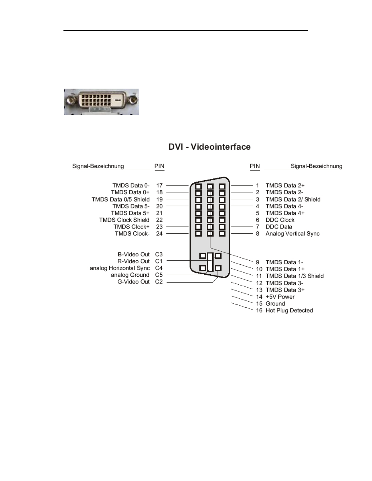
DVI
DVI-D
Dual Link
Page 26
Page 26 SRLine monitors user manual
SR SYSTEM-ELEKTRONIK GmbH | Eschachstr. 23| D-78078 Niedereschach | phone +49 77289268-0 | inf [email protected]
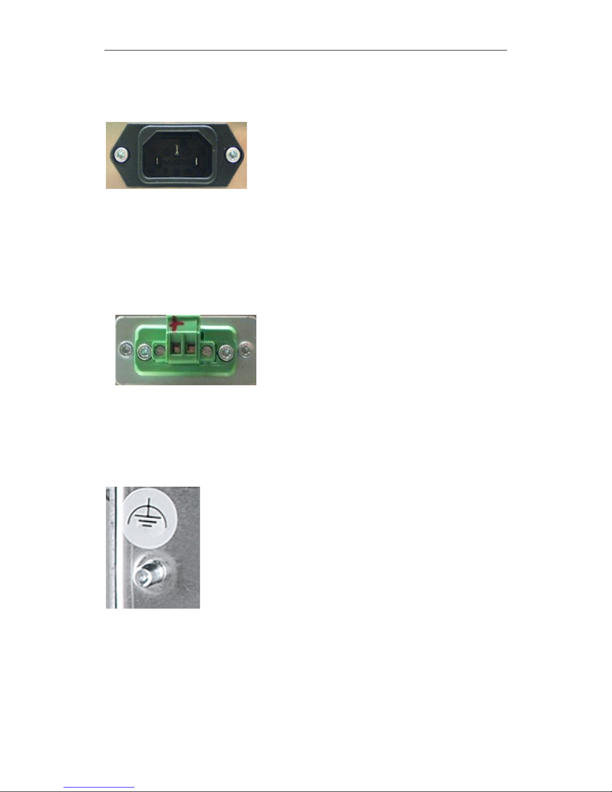
AC-supply unit
90 ~ 264 V AC
DC-connector 12 / 24 V
Phoenix
MSTB 2,5 / 2-STF-5,08
Ground bolt
Low Noise grounding earth function.
For proper function, espacially in conjunction with capacitive
touch.
 Loading...