

Page 1
(ACN 089 050 564 ABN 44 089 050 564)
8 Victoria Grove
Hawthorn East
VIC 3123
Australia
Page 2

SRK Electronics FMA501 manual
Safety notice
1 General description
2 Unpacking
3 Installation
4 Operation
4.1 Front panel
4.2 Rear panel
4.3 Switching on and off
4.4 Initial setup
4.5 Measuring other parameters
4.6 Setting power supply voltage
4.7 Setting the date and time
4.8 Protection
4.9 Remote operation
5 Maintenance
5.1 Recommended maintenance schedule
6 Circuit description
6.1 Equipment overview
6.2 Power supply
6.3 Control board
6.4 Amplifier palette
6.5 Output directional coupler
7 Trouble shooting
7.1 Diagnostics
7.2 Disassembly
Drawings
FMA501 Manual
2007 SRK Electronics Pty Ltd
1
Page 3
SRK Electronics FMA501 manual
Safety note
This equipment uses high voltages internally. Any servicing should be performed by
competent individuals.
Prolonged exposure to high level RF radiation has been shown to pose a health risk.
Whilst the equipment is intrinsically safe, its use in conjunction with an antenna
system may generate large RF fields. Appropriate precautions should be taken by
individuals that habitually work close to the transmitting antenna.
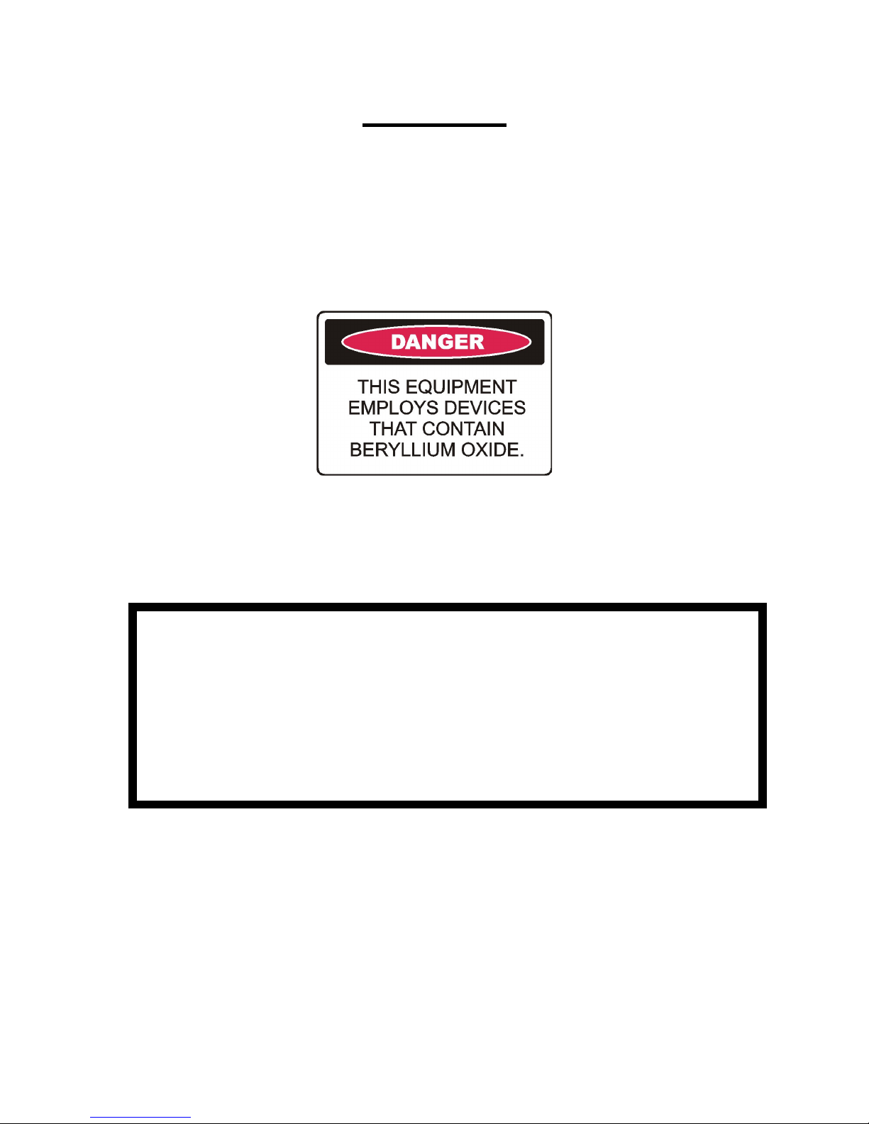
The RF power devices of this equipment employ Beryllium Oxide. This substance is
extremely toxic if pulverised. On no account should any RF power devices be
smashed. Please refer to attached Material Safety Data Sheet for further information.
WARNING
THIS EQUIPMENT IS SUPPLIED WITH A MAINS LEAD INCORPORATING
AN EARTH WIRE. IT IS IMPERATIVE THAT THIS EQUIPMENT IS
CONNECTED TO A MAINS OUTLET THAT HAS AN EARTH. IN
COUNTRIES WHERE EARTHED OUTLETS ARE NOT MANDATORY, IT IS
THE CUSTOMER’S RESPONSIBILITY TO ENSURE THAT THIS
EQUIPMENT IS APPROPRIATELY EARTHED.
2007 SRK Electronics Pty Ltd
2
Page 4

SRK Electronics FMA501 manual
1 GENERAL DESCRIPTION
The FMA501 is a high quality 500W amplifier intended for audio broadcast service in the FM
band.
Its features include:
• Wideband
• Energy efficient and high power factor
• Extensive metering
• Rugged design.
• Conservatively rated.
• Comprehensive telemetry.
• Flexible configuration.
Applications include standalone medium power transmitters and multiple units for high power
FM transmitters.
The FMA501 is designed and built in Australia.
2007 SRK Electronics Pty Ltd
3
Page 5

SRK Electronics FMA501 manual
2 UNPACKING
This section details the way in which the FMA501 should be unpacked upon receipt by the
customer.
Note that if the FMA501 is installed in an SRK Electronics transmitter then this section is not
applicable.
The FMA501 should be removed from its packing, and the packing stored and used should it
be necessary to return the FMA501 to the manufacturer.
Along with the amplifier, the following items should also be present:
• This manual
• Mains lead
The customer should ensure that all items are present and then store them in a safe place.
2007 SRK Electronics Pty Ltd
4
Page 6

SRK Electronics FMA501 manual
3 INSTALLATION
3.1 General
This section describes the installation and infrastructure requirements for the FMA501.
Departure from the instructions contained herein may void any warranty provided by SRK.
The FMA501 has been designed to be mounted in a standard 19” rack frame, where it will
occupy 3 rack units. Due to the weight of this unit, rear supports are also recommended.
However, the amplifier may also be used in a free standing situation, so long as all other
requirements are met as below.
3.2 Environmental
The amplifier is intended for indoor use. The amplifier should be protected from rainfall and
direct sunlight, extremes of temperature and humidity and from conditions of high dust levels.
The amplifier shall not be operated at altitudes in excess of 3500m above sea level. The
amplifier must be installed on a flat, stable surface. The amplifier must be installed in the
upright position. The amplifier must be installed in a location free from vermin and the ingress
of other animals. The amplifier shall not be installed in locations prone to flooding. All
ventilation orifices must be clear to allow adequate air flow.
3.3 Electrical supply
The electrical supply to the amplifier must be of the voltage, form and frequency described in
the specifications. All electrical wiring must be carried out in accordance with local laws,
standards and regulations. If power supply voltages regularly fall outside specifications then
a voltage regulator must be installed between the supply inlet and the amplifier.
3.4 Earthing
Adequate earthing of the amplifier is vital to ensure long term reliability and user safety. The
electrical supply must be earthed, via the earthing pin of the IEC connector. In countries
where power outlet earthing is merely optional, an earthed outlet must be used. See safety
notice at the front of this manual. A separate, independent, earth is required for the
amplifier/antenna system and must be connected to the earthing point indicated on the rear of
the amplifier. The cable used to connect the earth should be as thick as possible, with 8 AWG
being the smallest size acceptable. Where possible, broad earthing band should be used.
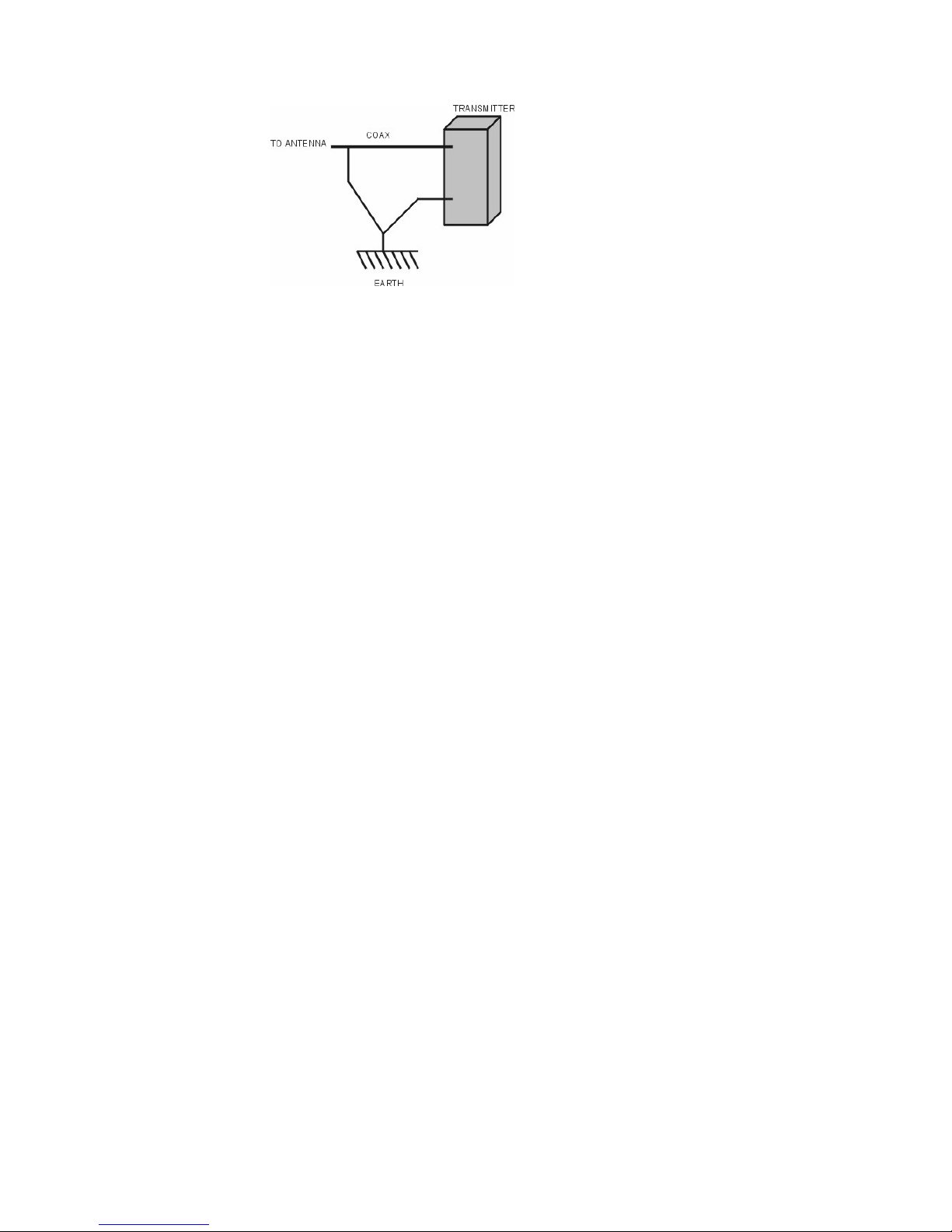
In addition to the earth connection to the amplifier, the outer conductor of the coax feed to the
antenna should be connected to the earth, as indicated below.
2007 SRK Electronics Pty Ltd
5
Page 7
SRK Electronics FMA501 manual
The earth itself must be of high quality buried copper, at least 1.5m deep and preferably in
ground that is habitually humid (eg, the base of a gutter down pipe).
3.5 Antenna
The antenna load connected to the amplifier must be tuned to minimise reflections. Whilst the
amplifier is designed to withstand high levels of reflection for short periods, continually high
levels of reflected power will degrade the long term reliability of the amplifier. Operating SWR
should be kept to below 1.9:1.
2007 SRK Electronics Pty Ltd
6
Page 8
SRK Electronics FMA501 manual
2007 SRK Electronics Pty Ltd
7
Page 9
SRK Electronics FMA501 manual
2007 SRK Electronics Pty Ltd
8
Page 10

SRK Electronics FMA501 manual
4 OPERATION
4.1 Front Panel
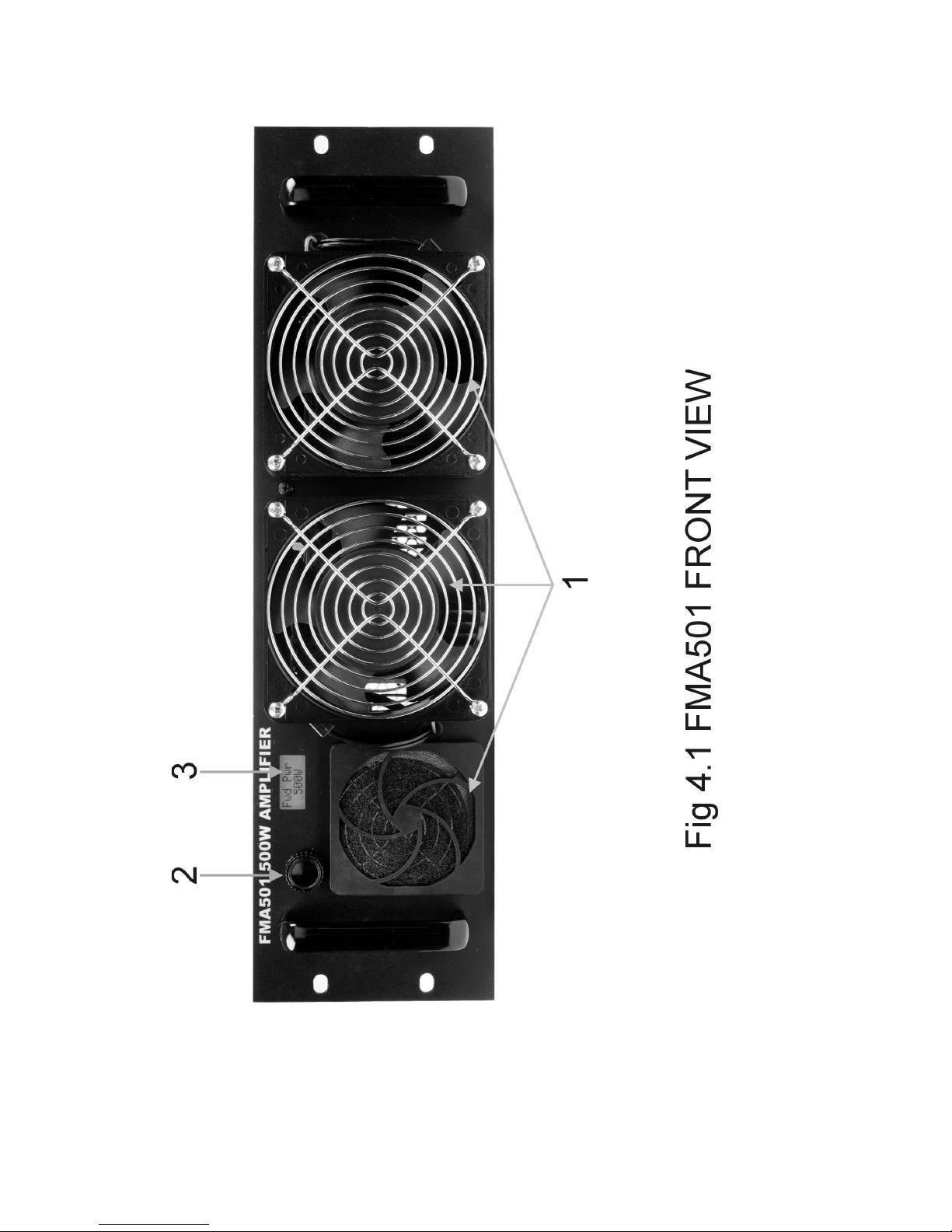
Please refer to figure 4.1. The numbers of the following paragraphs refer to the controls
shown in figure 4.1.
1 Air inlets
Allows cooling air to enter the amplifier. Under no circumstances must these be blocked.
2 Control knob
Used to select which parameter is displayed on the LCD. Also used to modify some
parameters.
3 LCD
The current parameter is displayed on the LCD, as well as any alarm conditions.
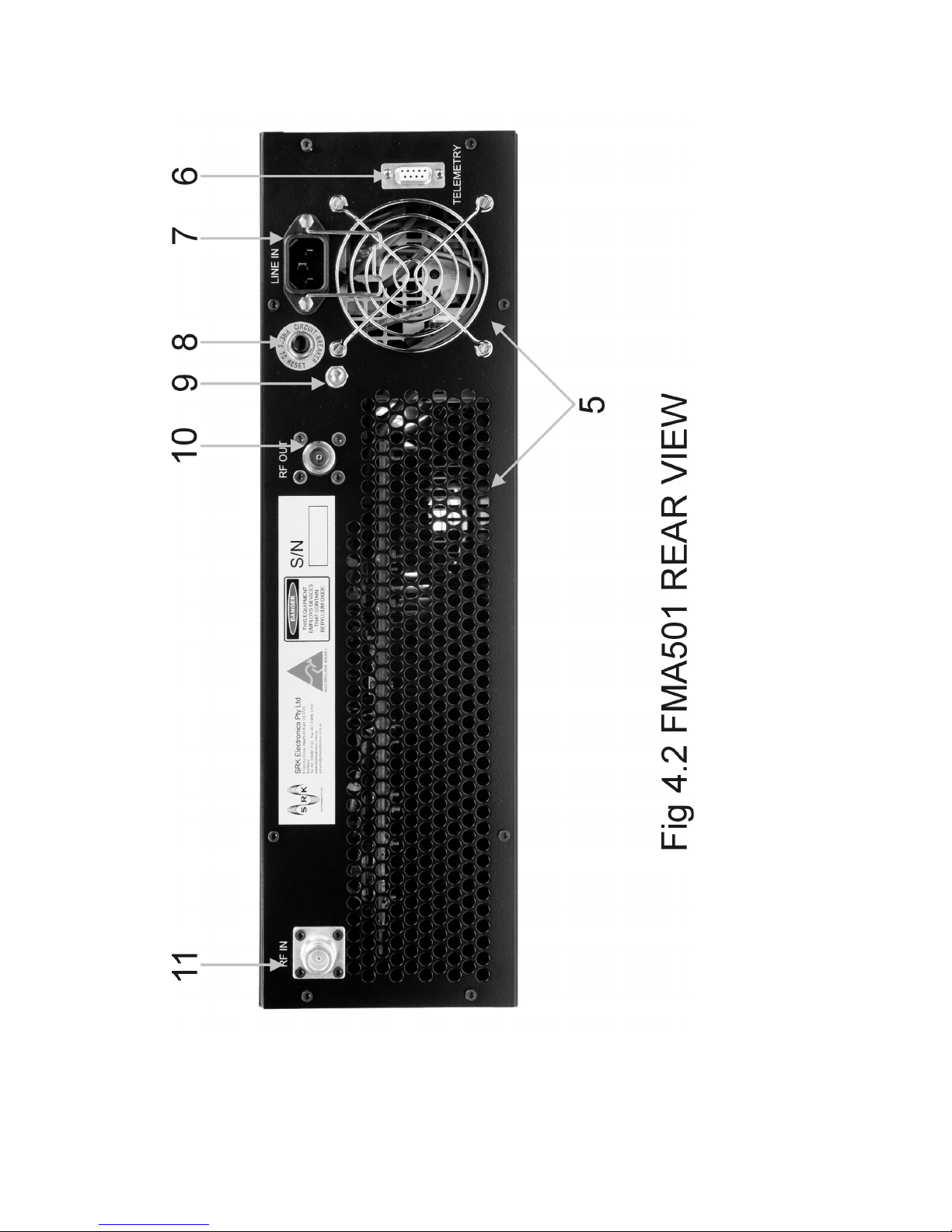
4.2 Rear panel.
Please refer to figure 4.2. The numbers of the following paragraphs refer to the controls
shown in figure 4.2.
5 Air outlets
Allows hot air to exit the amplifier. Under no circumstances must these be blocked, and any
external objects must be at least 500mm from the rear surface of the amplifier.
6 Remote connector
Remote operation is performed by making connection to this DB9 socket. Please refer to
section 4.9 for details
7 Mains input.
This is the mains input, 240V AC unless specified by the customer. Mating connector is IEC
female. Any connection made to this socket must incorporate a safety earth.
8 Mains circuit breaker
Mains over current protection. Button pops out under overload condition. Press to reset. If
fault persists investigate possible power supply failure.
9 Earth stud.
This is an M6 stud for connecting an earth. This is recommended for superior lightning
protection.
10 RF out.
This is the RF output and is connected to either the antenna (for stand-alone applications), or
the RF combiner unit. Mating connector is N type male, 50Ω.
11 RF in
This is the RF input and is connected to the driving exciter. Mating connector is N type male,
50Ω.
4.3 Switching on and off
The FMA501 is switched on by applying mains power. The LCD will light and show “Fwd
Pwr”, meaning forward power, in watts. The FMA501 is now in operating mode. Assuming
2007 SRK Electronics Pty Ltd
9
Page 11

SRK Electronics FMA501 manual
there are no alarms and the unit has not been put into standby mode previously, the fans
should start.
4.4 Initial setup
Assuming that the amplifier has been correctly installed, enough RF input power should be
applied to give the desired forward output power. Initially set the drive power to zero and
slowly increase until the forward power, as shown on the LCD, is at the required level. Note
that it is not advisable to generate powers in excess of 500W.
4.5 Measuring other parameters
Once the correct forward power has been established, the other amplifier parameters may be
checked. The available parameters are as follows and can be accessed in turn by rotating
the control knob clockwise to go down the list, or anticlockwise to go up the list:
“Fwd Pwr” Forward RF output power in watts
“Ref Pwr” Reflected RF output power in watts
“”I/P Pwr” Input RF power in watts
“A Temp” Amplifier A temperature in °C
“”Amp A I” Amplifier A DC current in amps
“B Temp” Amplifier B temperature in °C
“Amp B I” Amplifier B DC current in amps
“Amp Volt” Amplifier DC voltage in volts
“AC Volts” Input line voltage in volts
Data and time, British 24 hour format
“Elapsed” Total number of days running
Selecting any of these parameters has no effect on the operation of the amplifier
4.6 Setting power supply voltage.
When running at output powers of less than 300W, improved efficiency and lower device
dissipation can be achieved by reducing the amplifier DC supply voltage to lower than the
nominal 50V. This PSU cut function can be performed via the front panel by selecting the
“Amp Volt” parameter and then momentarily pressing the control knob inwards. It will be
noticed that the indicated voltage will drop to a nominal value of 35V. Pressing the button
again will return the voltage to 50V.
If desired, the PSU voltage in the cut state can be adjusted using VR16 on the control board.
For security, the ability to select/deselect this function using the front panel can be disabled
using the FD command via remote control.
4.7 Setting the date and time.
The current date and time can be set by selecting date and time using the control knob.
Pressing the knob momentarily will make the years value flash. Whilst it is flashing, rotate the
knob until the current year is displayed. Press the knob momentarily and the month will now
start flashing. Set as per years and continue through day, hours, minutes and finally seconds.
When done, press the knob again and the flashing will stop. The date and time have now
been set.
For security, the ability to select/deselect this function using the front panel can be disabled
using the FD command via remote control.
2007 SRK Electronics Pty Ltd
10
Page 12

SRK Electronics FMA501 manual
4.8 Protection
The FMA501 incorporates a number of protective features that make it extremely rugged.
If the reflected power from the antenna exceeds 50W then the output RF power will be
automatically reduced to bring the reflected power back to 50W. Under this condition the
FMA501 will continue to function, albeit at a reduced output power, indefinitely until the
reflected power reduces. The LCD will show “SWR HIGH”.
The forward power is limited to 550W. “RF HIGH” will be shown on the LCD under this
condition. RF input power should be reduced.
If the RF input power exceeds 20W, the amplifier will totally shutdown until the input power is
reduced to less than 10W.
If the temperature of the RF amplifier becomes excessive, then the RF output power will be
reduced to zero until the amplifier temperature falls to an acceptable level. During this time
the LCD will show “TEMPERATURE HIGH”. The upper limit for heatsink temperature is
85°C.
If the AC line voltage drops below 200V then the amplifier will shut down until line volts
exceeds 210V. The LCD will show “UNDER AC VOLTS”.
If the AC line voltage exceeds 275V then the amplifier will shut down until the line volts falls
below 260V. The LCD will show “OVER LINE VOLTS”.
4.9 Remote operation.
The FMA501 may be monitored and controlled remotely via the “TELEMTRY” connector on
the rear of the unit. This is an RS232 standard connection with the following characteristics:
Baud rate: 9600
Data bits: 8
Parity: NONE
Stop bits: 1
Flow control: NONE
The pinout for the DB9 connector is as follows: pin 2, transmit data, pin 3, receive data, pin 5,
common (0V). All other pins are not connected.
The FMA501 responds to the following commands. <CR> indicates the ASCII character 0D
hex. All letters are upper case, spaces (20 hex) are indicated by “_”. All commands must be
terminated by <CR>. Note that a line feed (0A hex) must not be sent before or after <CR>.
After a response is sent, a carriage return, line feed and “>” are sent.
FP?<CR>
Returns forward power in the form XXXW<LF><CR>>. For example:
FP?<CR> (command)
500W<LF><CR> (response from amplifier)
>
Note that for forward powers of 99W and below, the leading zero is replaced with a space
RP?<CR>
2007 SRK Electronics Pty Ltd
11
Page 13

SRK Electronics FMA501 manual
Returns reflected power in the form XXXW<LF><CR>>. For example:
RP?<CR> (command)
_00W<LF><CR> (response from amplifier)
>
Note that for reflected powers of 99W and below, the leading zero is replaced with a space.
IP?<CR>
Returns the input power in the form XX.XW<LF><CR>>. For example:
IP?<CR> (command)
_7.5W<LF><CR> (response from amplifier)
>
Note that for input powers of 9.9W and below, the leading zero is replaced with a space.
AAT?<CR>
Returns the amplifier A temperature in the form XXXC<LF><CR>>. For example:
AAT?<CR> (command)
_32C<LF><CR> (response from amplifier)
>
Note that for temperatures of 99C and below, the leading zero is replaced with a space.
AAI?<CR>
Returns amplifier A DC current in the form XX.XA<LF><CR>>. For example:
AAI?<CR> (command)
_7.5A<LF><CR> (response from amplifier)
>
Note that for currents of 9.9A and below, the leading zero is replaced with a space.
ABT?<CR>
Returns the amplifier B temperature in the form XXXC<LF><CR>>. For example:
ABT?<CR> (command)
_32C<LF><CR> (response from amplifier)
>
Note that for temperatures of 99C and below, the leading zero is replaced with a space.
ABI?<CR>
Returns amplifier B DC current in the form XX.XA<LF><CR>>. For example:
ABI?<CR> (command)
_7.5A<LF><CR> (response from amplifier)
>
2007 SRK Electronics Pty Ltd
12
Page 14

SRK Electronics FMA501 manual
Note that for currents of 9.9A and below, the leading zero is replaced with a space.
AV?<CR>
Returns the amplifier DC supply voltage in the form XX.XV<LF><CR>>. For example:
AV?<CR> (command)
50.1V<LF><CR> (response from amplifier)
>
Note that for voltages of 9.9V and below, the leading zero is replaced with a space.
LV?<CR>
Returns the line voltage in the form XXXV<LF><CR>>. For example:
LV?<CR> (command)
240V<LF><CR> (response from amplifier)
>
Note that for voltages of 99V and below, the leading zero is replaced with a space.
TD?<CR>
Returns the current time and date in the form XX:XX:XX_XX/XX/XX<LF><CR>>. For
example:
TD?<CR> (command)
14:27:07_02/05/06<LF><CR> (response from amplifier)
>
ET?<CR>
Returns the number of elapsed days the unit has been running in the form
XXXXX_DAYS<LF><CR>>. For example:
ET?<CR> (command)
__576_DAYS<LF><CR> (response from amplifier)
>
Note that the three leading zeros are blanked with spaces.
PS?<CR>
Returns the current front panel status. For example:
PS?<CR> (command)
Locked<LF><CR> (response from amplifier indicating that the front panel is locked)
>
or
Unlocked<LF><CR> (response from amplifier indicating that the front panel is unlocked)
>
ST?<CR>
Returns the current standby/running status. For example:
ST?<CR> (command)
Standby<LF><CR> (response from amplifier indicating that it is in standby)
>
or
2007 SRK Electronics Pty Ltd
13
Page 15

SRK Electronics FMA501 manual
Running<LF><CR> (response from amplifier indicating that it is running)
>
PC?<CR>
Returns the current PSU cut status. For example:
PC?<CR> (command)
Off<LF><CR> (response from amplifier indicating that PSU cut is off)
>
or
On<LF><CR> (response from amplifier indicating that PSU cut is on)
>
BS?<CR>
Returns the current self test status in the form XXXXX<LF><CR>>, where X can be either 0
or 1. A 1 indicates a failure, a 0 indicates a pass. The first byte indicates line volts high, the
second indicates line volts low, the third indicates high temperature, the fourth indicates a
high input RF condition, the fifth indicates a high SWR condition and the sixth indicates a high
RF output power condition. For further information consult the section on protection. For
example:
BS?<CR> (command)
000010<LF><CR> (response from amplifier indicating a high SWR condition)
>
or
000000<LF><CR> (response from amplifier indicating no failures)
>
FE<CR>
Unlocks the front panel to allow parameters to be altered locally. For example:
FE<CR> (command to enable the front panel)
Ok<LF><CR> (response from amplifier indicating that command has been
> executed)
FD<CR>
Locks front panel. Parameters can be measured but not changed locally. For example:
FD<CR> (command to disable front panel)
Ok<LF><CR> (response from amplifier indicating that command has been
> executed)
SD=XX/XX/XX<CR>
Sets the date according to XX/XX/XX. For example:
SD=23/07/06<CR> (command)
Ok<LF><CR> (response from amplifier indicating that command has been
> executed)
ST=XX:XX:XX<CR>
Sets the time according to XX:XX:XX. For example:
2007 SRK Electronics Pty Ltd
14
Page 16

SRK Electronics FMA501 manual
ST=11:45:32<CR> (command)
Ok<LF><CR> (response from amplifier indicating that command has been
> executed)
ON<CR>
Turns the amplifier on from a standby condition. The fans and the main PSU will start upon
receipt of this command. For example:
ON<CR> (command)
Ok<LF><CR> (response from amplifier indicating that command has been
> executed)
OFF<CR>
Turns the amplifier off into a standby condition. The fans and the main PSU will shutdown
upon receipt of this command. For example:
OFF<CR> (command)
Ok<LF><CR> (response from amplifier indicating that command has been
> executed)
PE<CR>
Enables PSU cut. The power supply voltage will drop to a nominal value of 35V upon receipt
of this command. For example:
PE<CR> (command)
Ok<LF><CR> (response from amplifier indicating that command has been
> executed)
PD<CR>
Disables PSU cut. The power supply voltage will rise to a nominal value of 50V upon receipt
of this command. For example:
PD<CR> (command)
Ok<LF><CR> (response from amplifier indicating that command has been
> executed)
HP?<CR>
Returns a summery of the above commands.
Any data received by the amplifier, other than the commands listed above will generate the
following error string:
Invalid_command.__Send_HP?(CR)_for_command_syntax.<LF><CR>
>
Any data outside the valid range for the parameter concerned will generate the following error
string:
Incorrect_value_or_syntax.__Send HP?(CR)_for_help.<LF><CR>
>
2007 SRK Electronics Pty Ltd
15
Page 17

SRK Electronics FMA501 manual
Should it be necessary to make connection to the remote port using cables running external
to the building housing the FMA501, it is recommended that external filtering and transient
protection be installed on these lines.
2007 SRK Electronics Pty Ltd
16
Page 18

SRK Electronics FMA501 manual
5 MAINTENANCE
5.1 Recommended maintenance schedule
The FMX501 will give many years of trouble free service with little or no attention
The air filter on the front panel should be regularly inspected and cleaned gently with warm
water if necessary.
If the operation of the date and time becomes erratic then replace the button cell on the
control board.
2007 SRK Electronics Pty Ltd
17
Page 19
SRK Electronics FMA501 manual
2007 SRK Electronics Pty Ltd
18
Page 20

SRK Electronics FMA501 manual
6 CIRCUIT DESCRIPTION
6.1 Equipment Overview
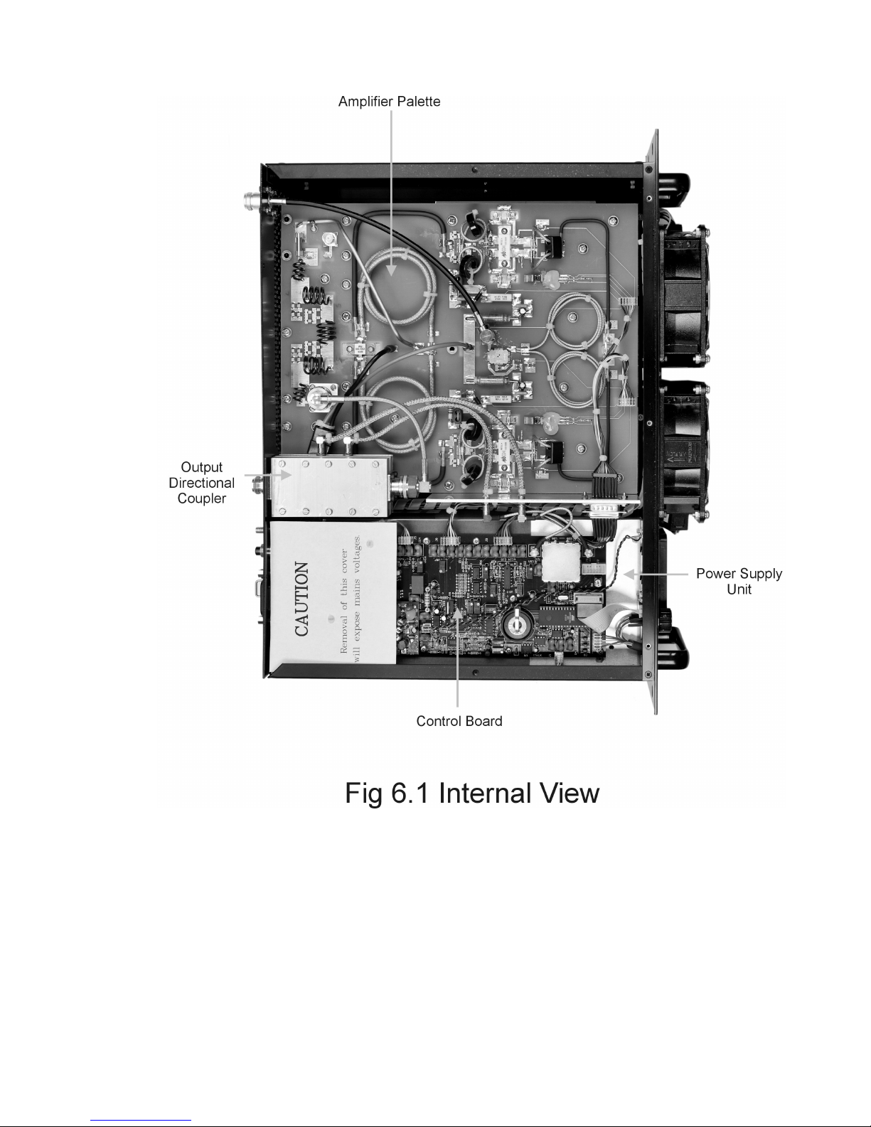
The FMA501 consists of the following sub-assemblies:
• Power Supply
• Control board
• Amplifier palette
• Output directional coupler
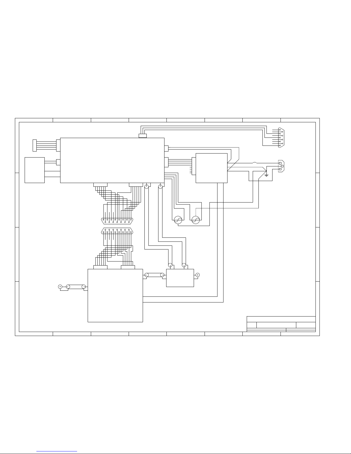
These assemblies are interconnected as per “FMA501 wiring diagram”.
Please refer to fig 6.1 for the physical location of each sub-assembly.
The power supply provides a nominal 50V DC for the RF transistors.
The control board contains all metering and protection functions.
The amplifier palette contains most RF functions.
The output directional coupler allows accurate metering of forward and reflected power.
6.2 Power Supply and Metering board
The power supply is an OEM unit, manufactured by Meanwell, p/n RFP-1500-48. Full
specifications can be found at www.meanwell.com.
Apart from the mains input and DC output, the control connector is used to switch the unit off
and on and to reduce the output voltage whilst PSU cut is enabled.
Energising the diode between pins 1 and 2 of CN2 switches the PSU off. A variable
resistance between pins 3 and 4 allows the output voltage to be reduced.
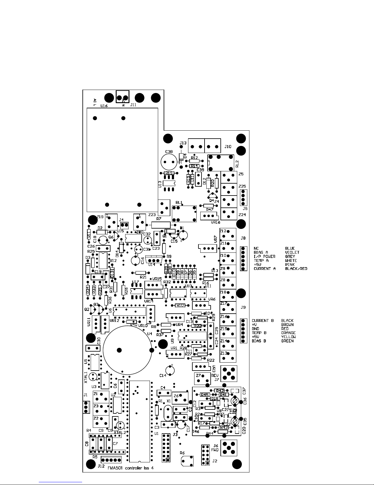
6.3 Control Board
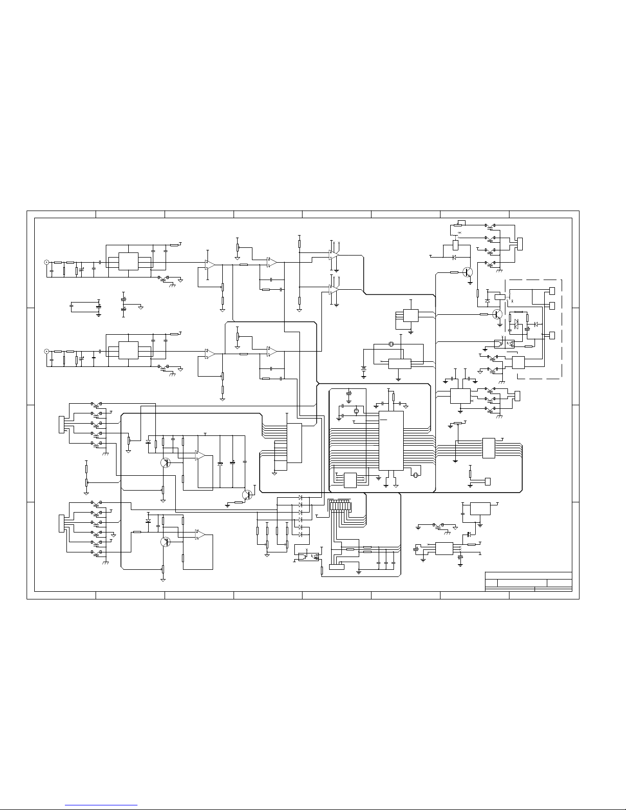
The control board is responsible for all measurement and protection functions. Refer to the
appropriate schematic.
The heart of the controller board is U1, a micro-controller unit. This performs the following
functions:
The analogue voltages representing the forward and reverse powers are digitised on pins 40
and 39. These values are then squared internally to allow the forward and reflected power to
be read on the front panel and via telemetry.
Due to the limited number of pins, all other analogue voltages to be read (input power,
amplifier currents, amplifier temperatures and DC supply voltage) are routed through an
external MUX (U6) into pin 38. Thus allowing these parameters to be measured.
Pin 36 provides a digital signal that is used to assert the PSU cut function. This is done by
energising RL1, via Q1. VR16 sets the actual voltage in the PSU cut state.
2007 SRK Electronics Pty Ltd
19
Page 21

SRK Electronics FMA501 manual
The signals from the rotary encoder are filtered and then passed to pins 33, 34 and 35.
Pins 22 and 23 provide an I²C bus which allows communication with the real time clock (U3)
and the flash memory (U5).
The LCD is controlled by the signals on pins 24, 26 and 27, as well as the data on pins
1,37,3,4,5,6,7 and 8.
The crystal connected to pins 28 and 29 provides an internal 1Hz clock for U1.
The two error conditions HIGH O/P and HIGH SWR are monitored on pins 20 and 21. These
signals are derived from the comparators U10 and U11. These devices monitor the forward
and reflected power control loops formed by U9B and U9C. If the output of U9B drops to less
than about 10V, this indicates that an over O/P power condition exists. Likewise U9C and a
high SWR condition.
U9B and U9C constantly compare the actual forward and reflected power with thresholds set
by VR3 and VR6 respectively. VR3 is set to the equivalent of about 550W of forward power.
VR6 is set to the equivalent of about 50W of reflected power. Either U9B or U9C can reduce
the bias voltage to the amplifier, thus reducing the output power. In this way, elegant and
seamless power and SWR protection are provided.
The forward and reflected RF voltages from the directional coupler are accurately converted
to DC levels by U7 and U8. U9A and U9D are used to scale these voltages so that 1000W
passing through the directional coupler provides 5.0V to the MCU.
Small value resistors in the supply lines of the MOSFETs on the amplifier palette generate
voltages proportional to the drain currents. These voltages are amplified and level shifted by
U12, Q2 and Q3. VR11 and VR12 are adjusted so that 20.48A of drain current produce 5.0V
into the MCU.
Gate bias for the MOSFETs is set by VR14 and VR15.
The AC line voltage is monitored by measuring the frequency of the relaxation oscillator
formed by R12, 14 and 15, C39 and D11. These pulses are passed via the optocoupler U13
into the MCU. As D4, C38 and R12,14 and 15 form a reasonable approximation to a constant
current source whose value is proportional to the peak AC voltage, the frequency of these
pulses is a reasonably accurate representation of the AC voltage.
Telemetry is provided by the on chip USART in the MCU, with U2 providing level shifting to
RS232 levels.
+15V for this board is provided by the small SMPSU, U16. U14 provides +5V from this for the
digital circuitry and U15 generates a nominal -9V for the analogue circuitry.
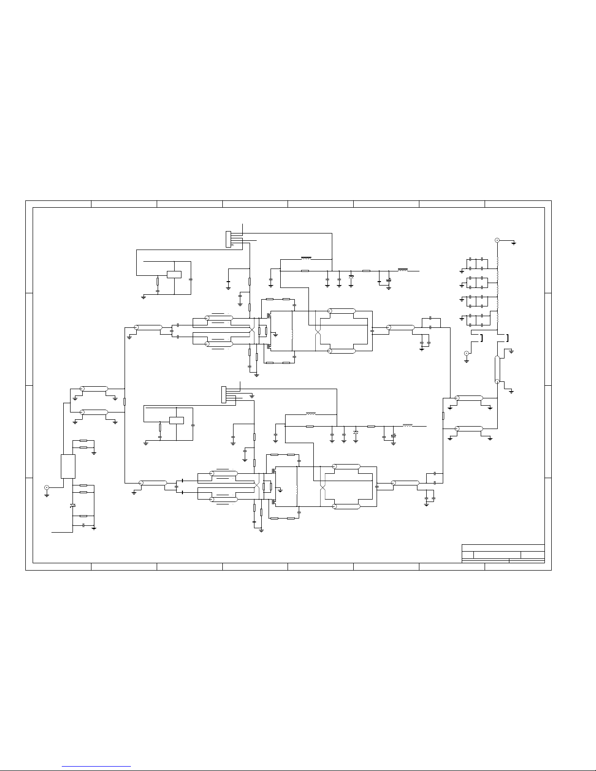
6.4 Amplifier palette
The amplifier palette performs the actual RF amplification. Please refer to the appropriate
schematic.
In brief, the RF is split into two paths, each consisting of a 250W class B amplifier (amplifier A
and amplifier B). The outputs from these amplifiers are combined and filtered to provide an
overall output power of 500W. A more detailed description follows:
RF enters the palette on J1 and passes through directional coupler U1. This provides a small
sample of the input power across R17 and R18. This is rectified by D1 which thus provides a
2007 SRK Electronics Pty Ltd
20
Page 22

SRK Electronics FMA501 manual
DC voltage proportional to the square root of the input power. This voltage is used by the
control board for measuring the input power.
Returning to the main RF path. The input power is split into two equal parts by the action of
T14, T15 and R20. This is a Wilkinson splitter of classic design.
Amplifier A and amplifier B are identical, so only amplifier A will be described. T12 forms a
balun so the right hand end has two voltages 180° out of phase with each other. The
impedance is stepped down to approximately 6Ω by the transmission line transformer formed
by T3 and T4. This is to provide a reasonable match into the gate impedance of Q1. R22-25
and C55,56 ensure stability when driving high Q loads such as cavity filters.
The drain load is transformed back up to 50Ω by the transmission line transformer formed by
T1 and T2. The balun formed by T9 generates a ground referenced signal once more.
This is then passed into the Wilkinson combiner formed by T16, T17 and R21.
The signal at T10 is thus a nominal 500W, unfiltered.
JP1 and JP2 are high current links which enable tuning of the output filter in isolation. JP2 is
only fitted during factory testing. JP1 is the only link fitted after production testing.
The filter formed by C38-53 and L3-7 ensures that all spurious and harmonic components are
adequately attenuated. This is a 9 pole Chebyshev filter with a minimum stop band
attenuation of 40dB at 175MHz and 60dB at 262.5MHz. Stop band attenuation is better than
60dB at frequencies up to 1GHz.
The filtered RF leaves the palette on J3.
Temperature measurement is provided by the two LM35 temperature sensors mounted near
each transistor. These return the temperature of the copper heat spreader.
6.5 Output directional coupler
The output directional coupler takes the high power RF from the amplifier palette and passes
it to the rear panel. A small sample of the forward and reflected voltages are provide, at
about 30dB down on the main line power.
These voltages are passed to the control board to allow forward and reflected power to be
measured and to ensure the correct operation of the protection functions.
The directional coupler is manufactured using stripline techniques and should not be
disassembled.
2007 SRK Electronics Pty Ltd
21
Page 23

SRK Electronics FMA501 manual
7 Trouble shooting
7.1 Diagnostics
Due to the extensive metering provided by the FMA501, diagnosing a failure becomes much
simpler.
Failure of the amplifier will generally result in a full or partial loss of output power. Careful
interpretation of the various parameters will generally indicate the likely cause of the problem.
For example, in the case of total loss of output power, the following routine should be used:
Does the LCD light and allow parameters to be measured? If not then suspect the control
board. Look for the presence of +15V, +5V and -9V power supply voltages.
Does the amplifier DC voltage read correctly. If not, suspect the main PSU.
Is there any RF input power shown as present? If not then the problem lies external to the
amplifier.
Do the amplifier A and amplifier B currents measure as normal? If not then suspect Q1 or Q2
on the amplifier palette.
Partial RF failure should be investigated in a similar manner, paying particular attention to
input power and the relative values of the amplifier DC currents. As a guide, these two
currents should be within 20% of each other. If not, suspect the transistor with the lower
current.
7.2 Disassembly
Commence by removing the IEC plug and all other external connections to the FMA501. This
is to ensure the safety of those undertaking the disassembly.
Remove the screws holding the upper lid and remove lid.
Remove all connections between the amplifier palette and the control board.
Remove the three cables between the amplifier palette and the output directional coupler.
Disconnect the red and black wires from the amplifier palette by pulling off the QC
connectors.
Disconnect the BNC plug on the input RF connector connected to the palette.
Turn the amplifier over and remove all the screws holding the lower lid.
Gently lift the lid, bringing the amplifier palette with it.
If needed, remove the 6 screws holding the amplifier palette to the lower lid.
To remove the control board, remove the two screws holding the protective cover in place.
Disconnect all connectors to the control board.
2007 SRK Electronics Pty Ltd
22
Page 24

SRK Electronics FMA501 manual
Remove the 10 screws holding the board to the PSU and gently lift out.
To remove the PSU, commence by turning the amplifier rear panel frontward and removing
the remaining screws holding the rear panel in place.
Gently pull the rear panel away to expose the mains wiring.
Undo the earth stud to free up the various earth wires.
Pull the blue wire off of the IEC socket and the brown wire which goes to the power supply off
of the circuit breaker.
The rear panel should now be free.
Remove the PSU from the side panel by removing the four screws holding it in place.
The PSU should now be free.
All the sub-assemblies should now be free of the chassis. Further disassembly should be self
evident.
2007 SRK Electronics Pty Ltd
23
Page 25
1 2 3 4 5 6 7 8
A
B
C
D
87654321
D
C
B
A
Title
Number RevisionSize
A3
Date: 1-Feb-2011 Sheet of
File: C:\Client98\Files\FMA501overall.sch Drawn By:
A
N
MAINS IN
IEC MALE
BR
BL
10A
FAN FAN
1
2
J11
MTA156-2
1
2
3
4
J5
MTA100-4
1
2
3
4
5
6
7
8
CN2
DF11-8
12345
6
J9
MTA100-6
12345
6
J8
MTA100-6
192103114125136147158
DB15
192103114125136147158
DB15
12345
6
J4
MTA100-6
12345
6
J5
MTA100-6
1
6
2
7
3
8
4
9
5
TELEMETRY
123
J1
MTA100-3
1
2
J4
MTA100-2
14WAY IDC
1
2
3
4
5
ROTARY ENCODER
1
2
3
4
5
J12
MTA100-5
N TYPE
RF OUT
N TYPE N TYPE
RG303
BNC
RG58
N TYPE
RF IN
CABLE COLOUR DESIGNATION
BK BLACK
BR BROWN
R RED
O ORANGE
Y YELLOW
GN GREEN
BL BLUE
V VIOLET
GY GREY
W WHITE
P PINK
BK/R BLACK/RED
GN/Y GREEN/YELLOW
R
BK
QC
QC
AMPLIFIER PALETTE
DIRECTIONAL COUPLER
SMB
RG316
SMB
RG316
SMB
SMB
FWD REV
POWER SUPPLY
CONTROL BOARD
LCD
BKRK
A
J10
J13
V+ V-
N
E
L
BKBKBK
BK
GN/Y
GN/Y
GN/Y
GN/Y
BR
GN
W
Y
BR
BL
BR
R
O
Y
BR
R
O
Y
GN
BK
BR
R
O
Y
GN
BL
V
GYWP
BK/R
FMA501 WIRING DIAGRAM
J1
J3
Page 26
1 2 3 4 5 6 7 8
A
B
C
D
87654321
D
C
B
A
Title
Number RevisionSize
A2
Date: 1-Feb-2011 Sheet of
File: C:\Client98\Files\fma501cont4.sch Drawn By:
PA0
40
PA1
39
PA2
38
PA3
37
PA4
36
PA5
35
PA6
34
PA7
33
XTAL2
12
XTAL1
13
RESET
9
AREF
32
PB0
1
PB1
2
PB2
3
PB3
4
PB4
5
PB5
6
PB6
7
PB7
8
PC0
22
PC1
23
PC2
24
PC3
25
PC4
26
PC5
27
PC6
28
PC7
29
PD0
14
PD1
15
PD2
16
PD3
17
PD4
18
PD5
19
PD6
20
PD7
21
+5
10
A+5
30
GND11AGND
31
U1
ATMEGA16(40)
X1
7.3728 MHz
C1
22p
C2
22p
VCC
VCC
C3
100n
C4
100n
FWD VOLTS
REV VOLTS
RXD
TXD
LCD 0
LCD 1
LCD 3
LCD 4
LCD 5
LCD 6
LCD 7
HIGH SWR
R1
10R
LCD 2
HIGH O/P
LCD R/S
LCD R/W
LCD E
VCC
VCC
LCD R/S
LCD R/W LCD E
LCD 0 LCD 1
LCD 2 LCD 3
LCD 4 LCD 5
LCD 6 LCD 7
DA2DY
7
VCC+
8
VCC-
1
GND
4
RA
5
RESP
6
RY
3
U2
SN75155
+15V-9V
C5
100n
C6
100n
Z1
DSS9
Z2
DSS9
Z3
DSS9
RXD
TXD
A
B
PB
VCC
C7
33nF
C8
33nF
C9
33nF
1 2
R4A
10K
3 4
R4B
10K
5 6
R4C
10K
987654321
R5
10K
RESET
RESET
1
2
3
J1
RS232
PB
A
B
C14
10uF
C15
10uF
C16
10uF
-9V
+15V
C23
100nF
VCC
C17
10uF
R6
10K
1 2
3 4
5 6
7 8
9 10
J2
SPI
SCL
SDA
LCD 5
VCC
X11X2
2
VBAT
3
GND
4
SDA
5
SCL6SQW/OUT
7
VCC
8
U3
DS1307(8)
VCC
U4
BATTERY
XTAL1
32KHz
VCC
8
GND
4
A0
1
A1
2
A2
3
WP
7
SCL
6
SDA
5
U5
24LC512
VCC
MUX
SCL
SDA
SDA
SDA
SCL
SCL
12
34
56
78
910
1112
1314
J3
LCD
1
2
J4
LED
+15V
R7
150R/1W
FAN ON
RL1
WJ102-1C-12
NC
NO
+15V
D1
1N4148
Q1
BC547
R9
10K
PSU CUT
X0
13
X1
14
X2
15
X3
12
X4
1
X5
5
X6
2
X7
4
INH
6
A
11
B
10
C
9
VEE
7
X
3
VCC
16
GND
8
U6
4051
MUX
MUXA
MUXB
MUXC
MUXA
MUXB
MUXC
VPOS
1
IREF
2
RF IN
3
PWDN
4
COMM
5
FLTR
6
VRMS
7
SREF
8
U7
AD8361
C10
1nF
J6
FWD
C28
1nF
R17
62R
Z4
DSS9
Z6
DSS9
3
2
1
411
U9A
TL074
5
6
7
U9B
TL074
VR1
10K
R22
4K7
-9V
+15V
R27
100K
R28
100K
C24
100nF
C11
10nF
+15V
VR3
10K
VPOS
1
IREF
2
RF IN
3
PWDN
4
COMM
5
FLTR
6
VRMS
7
SREF
8
U8
AD8361
C12
1nF
J7
REV
C29
1nF
R18
62R
Z7
DSS9
12
13
14
U9D
TL074
10
9
8
U9C
TL074
VR4
10K
R24
4K7
R29
100K
R30
100K
C25
100nF
C13
10nF
+15V
VR6
10K
FWD VOLTS
REV VOLTS
2
3
7
6
5184
U10
LM311
2
3
7
6
5184
U11
LM311
-9V
-9V
+15V
+15V
R32
4K7
R10
10K
+15V
HIGH SWR
HIGH O/P
HIGH O/P
HIGH SWR
1
2
3
4
5
6
J8
Amp A
Z8
DSS9
Z9
DSS9
Z10
DSS9
Z11
DSS9
Z12
DSS9
VCC
TEMP A
VR7
10K
BIAS CUT
IP VOLTS
R33
1K
VR11
47K
D2
12V
Q2
2N5401
R25
4K7
R34
1K
R11
430R
C18
10uF
C26
100nF
+V
R13
10K
TEMP A
AMP A CURR
AMP A CURR
R35
1K
VR12
47K
Q3
2N5401
R26
4K7
R36
1K
+V
R16
10K
AMP B CURR
1
2
3
4
5
6
J9
Amp B
Z13
DSS9
Z14
DSS9
Z15
DSS9
Z16
DSS9
Z17
DSS9
VCC
TEMP B
Z18
DSS9
+V
TEMP B
AMP B CURR
AMP VOLTS
VR10
10K
R31
100K
+V
AMP VOLTS
R2
10R
VCC
VCC
R3
10R
VCC
Vin
1
GND
2
+5V
3
U14
MC7805
C30
330nF
VCC
Z19
DSS9
Z20
DSS9
1
2
J11
240VAC
IP VOLTS
VR14
10K
VR15
10K
D5 1N4148
D6
1N4148
D7
1N4148
D8
1N4148
R381KR391KR8
10K
R37
10K
+15V
D9 1N4148
D10
1N4148
U17
4N23
-9V
VCC
R40
220R
BIAS CUT
Z23
DSS9
R4139R
R42
39R
R45
13R
R43
39R
R44
39R
R46
13R
-18dB
-18dB
12345
J12
ENCODER
C21
10nF
C22
10nF
Z24
DSS9
XTAL2
32KHz
+15V
TEST
1
CAP+
2
GND
3
CAP-4VOUT
5
LV
6
OSC
7
V+
8
U15
7660
C31
10uF
C32
10uF
+15V
-9V
+15V
V+
V- AC N
AC L
U16
OFM-0100
VR16
10K
PSU CUT
RL2
+15V
D12
1N4148
Q4
BC547
R47
10K
FAN ON
Z5
DSS9
Z25
DSS9
+15V
1
2
3
4
J5
PSU CONTROL
1
2
J10
FAN
1
2
J13
FAN
C33
4.7pF
C34
4.7pF
C35
15-60pF
C36
15-60pF
R20
2K2
+15V
Q6
BC547
VCC
3
2
1
84
U12A
LMC6462
5
6
7
U12B
LMC6462
D3
1N4148
C19
100pF
D13
1N4148
C27
100pF
VAC
C20
33pF
C37
33pF
D4
GP02-40
C38
3.3uF/450V
R12
510K
R14
510K
R15
RS 198-961
C39
33nF MKC
U13
CNY17-1
D11
DB3
R19
47R
VAC
R21
220R
D14
9V1
FMA501 CONTROL BOARD
Page 27
1 2 3 4 5 6 7 8
A
B
C
D
87654321
D
C
B
A
Title
Number RevisionSize
A2
Date: 1-Feb-2011 Sheet of
File: C:\Client98\..\FMA501 amp palette.sch Drawn By:
R1
75R
C1
1uF
C2
1uF
LM35
+5V
Q1B
MRF151G
Q1B
MRF151G
T1
RG316
T2
RG316
T9
141 HARDLINE
T3 RG316
T4 RG316
T12
86 HARDLINE
C5
470pF ATC100B
C6
470pF ATC100B
C16
68pF
R3
10K
R7
10R
C7
1nF
R8
10R
R4
10K
C8
1nF
C18
470pF
C19
470pF
C9
1nF
FB1
VK200
C20
470pF
R11
15R/1W
C30
100nF/100V
C34
10uF/100V
C22
470pF
C23
470pF
C36
15pF
+50V
R13
10mR
R2
75R
C3
1uF
C4
1uF
LM35
+5V
L1
45nH
T14
RG179
T15
RG179
IN
FWD REV
OUT
U1
11302-20
J1
RF IN
R15
100R
R16
100R
R17
100R
R18
100R
R19
100K
D1
5082-2800
C10
1nF
R20
RFP-10--100
T16
RG302
T17
RG302
R21
RFP250-100
T10
141 HARDLINE
1
2
JP1
1
2
JP2
J2
BNC
L3
L4
L5
L6
L7
J3
RF OUT
C38
22pF
C39
22pF
C42
36pF
C43
36pF
C44
36pF
C45
36pF
C50
39pF
C51
39pF
C52
39pF
C53
39pF
C46
36pF
C47
36pF
C48
36pF
C49
36pF
C40
22pF
C41
22pF
L8
5uH
C54
4.7nF
C31
100nF/100V
D2
61V/5W
R22
RFP-10-100
R23
RFP-10-100
R24
RFP-10-100
R25
RFP-10-100
C55
4.7nF
C56
4.7nF
Q2A
MRF151G
Q2B
MRF151G
T5
RG316
T6
RG316
T11
141 HARDLINE
T7 RG316
T8 RG316
T13
86 HARDLINE
C11
470pF ATC100B
C12
470pF ATC100B
C17
68pF
R5
10K
R9
10R
C13
1nF
R10
10R
R6
10K
C14
1nF
C24
470pF
C25
470pF
C15
1nF
FB2
VK200
C26
470pF
R12
15R/1W
C32
100nF/100V
C35
10uF/100V
C28
470pF
C29
470pF
C37
15pF
+50V
BIAS
R14
10mR
L2
45nH
L9
5uH
C57
4.7nF
C33
100nF/100V
D3
61V/5W
R26
RFP-10-100
R27
RFP-10-100
R28
RFP-10-100
R29
RFP-10-100
C58
4.7nF
C59
4.7nF
1
2
3
4
5
6
J4
1
2
3
4
5
6
J5
+5V
I/P POWER
I/P POWER
+50V
+5V
FMA501 AMPLIFIER PALETTE
R30
10R/1W
R31
10R/1W
R32
10R/1W
R33
10R/1W
Page 28
Page 29

MATERIAL SAFETY DATA SHEET
I PRODUCT IDENTIFICATION
Trade Name: Beryllia Ceramic Chemical Family: Beryllium Compound
Synonym: Beryllium Oxide, Beryllia, Thermalox, Super Beryllia
II HAZARDOUS INGREDIENTS
Constituents OSHA(1995)* ACGIH(1994-95)* CAS # NIOSH/ RTECS #
Beryllium PEL: 0.002 TLV: 0.002 7440-41-7 (Be) DS1750000
Ceiling: 0.005 TLV-STEL: NA 1304-56-8 (BeO) DS4025000
Peak: 0.025
*All concentrations are in mg/m3 (at the concentrations noted above, this constituent may not be visible to the human eye).
ESPI recommends the following good industrial hygiene practice which includes reducing airborne exposures to the lowest
feasible level for all constituents in this product. A leading scientific body recommending occupational standards is the American
Conference of Governmental Industrial Hygienists (ACGIH). The ACGIH recommends standards for all listed substances. The
ACGIH defines a threshold limit value (standards) as follows: “Threshold Limit Values refer to airborne concentrations of substances
and represent conditions under which it is believed that nearly all workers may be repeatedly exposed day after day without adverse
health effects.”
Because of wide variation in individual susceptibility, however, a small percentage of workers may experience discomfort
from some substances at concentrations at or below the threshold limit; a smaller percentage may be affected more seriously by
aggravation of a pre-existing condition or by development of an occupational illness. “Individuals may also be hyper-susceptible or
otherwise unusually responsive to some industrial chemicals because of genetic factors, age, personal habits (smoking, alcohol, or
other drugs), medication, or previous exposures. Such workers may not be adequately protected from adverse health effects from
certain chemicals at concentrations at or below the threshold limits.”
III PHYSICAL DATA
Boiling Point: N/A Sublimes At: N/A
Evaporation Rate: N/A Vapor Density (Air=1): N/A
Freezing Point: N/A Vapor Pressure (mm Hg): N/A
Odor: None % Volatile By Volume: None
pH: N/A Color: White
Physical State: Solid Melting Point (oF): 2547 (BeO)
Radioactivity: N/A Molecular Weight: 25.01 (BeO)
Solubility: None Density (g/cc): 2.86 (BeO)
IV FIRE AND EXPLOSION HAZARDS DATA
Flash Point: N/A Explosive Limits: N/A
Extinguishing Media: N/A
Unusual Fire and Explosion Hazards: N/A
Special Fire Fighting Procedures: If this material becomes airborne as a respirable particulate during a fire situation, pressure-
demand self-contained breathing apparatus must be worn by firefighters or any other persons potentially exposed.
Page 30

V HEALTH HAZARD INFORMATION
Emergency Overview: If this material is involved in a fire, pressure-demand self-contained breathing apparatus and protective
clothing must be worn by persons potentially exposed to the metal fumes or airborne particulate.
Primary Routes of Exposure:
Inhalation: An exposure to airborne beryllium in excess of the occupational standard can occur when sintering, machining, grinding,
sanding, abrasive cutting, polishing, laser scribing and trimming, chemical etching, crushing, or otherwise abrading the surface of this
material in a manner which generates finely divided particles.
Volatile beryllium hydroxide can be formed when firing solid BeO parts at temperature greater than 900 oC in a moist
atmosphere such as in a hydrogen atmosphere sintering furnace.
Machining operations conducted under a flood of liquid coolant usually require complete hooded containment and local
exhaust ventilation. Openings into the hood must be baffled to prevent release of fast moving particles. The cycling through a
machine of liquid lubricant/coolant containing finely divided beryllium in suspension can result in the concentration building to a
point where the particulate may become airborne during use. The coolant reservoir should be enclosed and ventilated. A coolant
filtering system is recommended.
The Potential for Exposure Also May Occur During Repair or Maintenance Activities on Contaminated Equipment Such as:
furnace rebuilding, maintenance or repair of air cleaning equipment, structural renovation, etc.
Ingestion: There are no known cases of illness resulting from ingestion of this material. Ingestion can occur from hand, clothing,
food, and drink contact with metal dust, fume or powder during hand to mouth activities such as eating, drinking, smoking, nail
biting, etc. This product is not intended for internal consumption. As a standard hygiene practice, hands should be washed before
eating or smoking.
Skin: Skin abrasion may cause irritation. Imbedded material may lead to localized granuloma. The beryllium in this material is in an
insoluble form and does not pose a potential for an allergic dermal response.
Eyes: Injury can result form particulate irritation or mechanical injury to the eyes by dust or particulate. Exposure may result from
direct contact with airborne particulate (chips, dust, or powder) or contact to the eye if contaminated hands or clothing.
Effects of Overexposure:
Acute: (immediate or near-term health effects): The beryllium fraction of this product is insoluble and does not cause acute beryl-
lium disease. The beryllium in this product does not pose a potential for allergic dermal response.
Chronic: (long-term health effects): Inhaling dust fumes containing beryllium may cause serious, chronic lung disease called
Chronic Beryllium Disease (CBD) in some individuals. Over time lung disease can be fatal. Symptoms may include cough, chest
pain, shortness of breath, weight loss, weakness, and fatigue. Long-term effects may include loss of lung function, fibrosis, or
subsequent secondary effects on the heart with eventual permanent impairment. Chronic beryllium disease is a hypersensitivity of
allergic condition in which tissues of the lungs become inflamed with a cellular nodular reaction. This inflammation, sometimes with
accompanying fibrosis, may restrict the exchange of oxygen between the lungs and the bloodstream. This allergic response to
beryllium is limited to susceptible studies and animal experimentation, the International Agency for Research on Cancer and the
National Toxicology Program lists beryllium as a carcinogen.
Medical Conditions Generally Aggravated by Exposure: Persons with impaired pulmonary function, airway diseases, or conditions such as asthma, emphysema, chronic bronchitis, etc. may incur further impairment if dust of fume are inhaled. If prior damage
or disease to the neurological (nervous), circulatory, hematologic (blood), or urinary (kidney) systems has occurred, proper screening
or examinations should be conducted on individuals who may be exposed to further risk where handling and use of this material may
cause exposure.
EMERGENCY AND FIRST AID PRODCEDURES:
INHALATION: Breathing difficulty cause by inhalation of dust or fume requires immediate removal to fresh air. There are no
known cases in which a person stopped breathing as a result of exposure. If breathing has stopped, perform artificial respiration and
obtain medical help.
Page 31

INGESTION: Swallowing beryllium oxide dust can be treated by having the affected person drink large quantities of water and
attempting to induce vomiting, if conscious. Obtain medical help.
SKIN: Skin cuts and abrasions should be treated by standard first aid. Skin contamination can be removed by washing with soap and
water. Obtain medical help if irritation persists. Accidental implementation of this material beneath the skin requires it be removed to
prevent infection or development of a corn-like lesion.
EYES: Dust should be flushed from the eyes with a lot of clean water. Obtain medical help if irritation persists. Contact lenses
should not be worn when working with metal dusts and powders because the contact lens must be removed to provide adequate
treatment.
Treatment of Chronic Beryllium Disease: There is not known treatment which will cure chronic beryllium disease. Prednisone or
the corticosteroids are the most specific treatment available. They are directed at suppressing the immunological reaction and have
been effective in diminishing many signs and symptoms of chronic beryllium disease. In cases where steroid therapy has had only a
partial or minimal effectiveness, other immuno-suppressive agents, such as cyclophospharnide, cyclosporine, or methotrexate, have
been used. These latter agents remain investigational. Further, in view of the potential side effects of all the immuno-suppressive
medications, including steroids such as prednisone, they should be used only under the direct care of a physician. In general, these
medications should be reserved for cases with significant symptoms and/or significant loss of lung function. Other symptomatic
treatment, such as oxygen, inhaled steroids or bronchodilatores, may be used by some physicians and
are effective in selected cases.
The decision about when and with what medication to treat is judgement situation for individual physicians. For the most
part, treatment is reserved for those persons with symptoms and measurable loss of lung function. The value of starting oral steroid
treatment, before signs or symptoms are evident, remains a medically unresolved issue currently under study. Some physicians are
concerned that their patients may develop a resistance to medication if it is started too soon.
The effects of continued low exposure to beryllium are unknown for individuals who are sensitized to beryllium or who have
diagnosis of chronic beryllium disease. This uncertainty leads some physicians to advise a reduction or elimination of further
exposure to beryllium. However, some individuals have developed CBD or have gradually become worse after removal from further
exposure. Others have continued to work in the beryllium industry without any additional, or accelerated, loss of lung function.
VI REACTIVITY DATA
General Reactivity: This material is stable
Incompatibility (Materials to avoid): NA
Hazardous Decomposition Products: None under normal conditions of use
Hazardous Polymerization: Will not occur
Ecological Information: This material is insoluble in water. This material can be recycled.
VII SPILL OR LEAK PROCEDURES
Steps to be Taken in Case Material is Released or Spilled: In solid form this material poses no health or environmental risk. If this
material is in powder or dust form, establish a restricted entry zone based on the severity of the spill. Persons entering the restricted
zone must wear adequate respiratory protection and protective clothing appropriate for the severity of the spill. Cleanup should be
conducted with a vacuum system utilizing a high efficiency particulate air filtration system followed by wet cleaning methods.
Special care must be taken when changing filters on HEPA vacuum cleaners when used to clean up potentially toxic materials.
Caution should be taken to minimize airborne generation of powder or dust and avoid contamination of air and water. Depending
upon the quantity of material released, fine powder or dust spills to the environment may require reporting the National Response
Center at (800) 424-8802 as well as the State Emergency Response Commission and Local Emergency Planning Committee.
Handling and Storage: Wear gloves when handling to prevent cuts and skin abrasions. Store in a dry area.
Ventilation and Engineering Controls: Whenever possible, the use of local exhaust ventilation or other engineering controls is the
preferred method of controlling exposure to airborne dust and fume. Where utilized, pickups on flexible ventilation lines should be
positioned as close to the source of airborne contamination as possible. Disruption of the airflow in the area of a local exhaust inlet,
such as by a man cooling fan, should be avoided. Ventilation equipment should be checked regularly to ensure it is functioning
properly. Ventilation training is recommended for all users. Ventilation systems designed and installed by qualified professionals.
Page 32

Respiratory Protection: When potential exposures are above the occupational limits shown in this MSDS, approved respirators must
be used as specified by an Industrial Hygienist of other qualified professional. Respirator users must be medically evaluated to
determine if they are physically capable of wearing a respirator. Quantitative an/or qualitative fit testing and respirator training must
be satisfactorily completed by all personnel prior to respirator use. Users of any style respirator training must be clean shaven on
those areas of the face where the respirator seal contacts the face. Exposure to unknown concentrations of fumes or dusts requires the
wearing of a pressure-demand airline respirator or pressure-demand self-contained breathing apparatus. Pressure-demand airline
respirators are recommended when performing jobs with high potential exposures such as changing filters in a bag house air cleaning
device.
Housekeeping: Vacuum and wet cleaning methods are recommended for dust removal. Be certain to de-energize electrical systems,
as necessary, before beginning wet cleaning. Vacuum cleaners with high efficiency particulate air (HEPA) filters are the recommended type. The use of compressed air or brooms to remove dusts should be avoided as such an activity can result in unnecessary
short-term elevated exposures to airborne dusts.
Maintenance: During repair or maintenance activities the potential exists for exposures in excess of the occupational standard.
Under these circumstances, protecting workers can require the use of specific work practices or procedures involving the combined
use of ventilation, wet methods, respiratory protection, decontamination, special protection clothing, and when necessary, restricted
work zones.
Other Protective Equipment: No special protective equipment or clothing is requires when handling solid forms. Protective over
garments or work clothing must be worn by persons who may become contaminated with dusts, fumes, or powders during activities
such as machining, furnace rebuilding, air cleaning equipment filter changes, maintenance, etc. Contaminated work clothing and over
garments must be managed in such a manner so as to prevent secondary exposure to persons such as laundry operators and to prevent
contamination to personal clothing. Never use compressed air to clean work clothing.
Protective Gloves: Wear gloves to prevent cuts and skin abrasions during handling.
Eye Protection: Wear safety glasses, goggles, or face shield when risk of eye injury is present, particularly during machining,
grinding, etc.
Recommended Monitoring Procedures:
Environmental Surveillance: Exposure to airborne materials should be determined by having air samples taken in the employee
breathing zone, work area, and department. The frequency and type of air sampling should be as specified by an Industrial Hygienist
or other qualified professional. Air sample results should be make available to employees.
Medical Surveillance: Persons exposed to airborne concentrations of this material should be included in a periodic medical surveillance program. The program should include examination of the skin and respiratory systems. Non-specific findings of skin rash, skin
granulomata, or respiratory signs or symptoms may indicate a reaction to this material. A minimum medical surveillance program
should include (1) skin examination, (2) respiratory history, (3) auscultation of the lungs, (4) spirometry (FVC and FEV), and (5)
periodic chest x-ray. In addition, a specialized, specific, immunological blood test, the beryllium blood lymphocyte proliferation test
(BLPT), is available ( on a limited basis to assist in the diagnosis) to screen beryllium-exposed persons for beryllium reactions. Note:
It should be recognized that BLPT has limited sensitivity for chronic beryllium disease. Individuals who have an abnormal BLPT are
normally referred to a lung specialist for additional specific tests to determine if chronic beryllium disease is present.
Page 33

VIII SPECIAL PROTECTION INFORMATION
Transport Information: There are nor U.S. Department of Transportation hazardous material regulations which apply to the
packaging and labeling of this product as shipped by ESPI. Hazard Communication regulations of the U.S. Occupational Safety and
Health Administration require that this material be labeled.
Regulatory Information: OSHA Hazard Communications Standard, 29 CFR 1910.1200: Beryllium is considered a hazardous
ingredient.
Ambient Air Emissions: Beryllium-containing materials are subject to the National Emission Standard for Beryllium as promulgated
by EPA (40 CFR 61, Subpart (C). The National Emission Standard for beryllium is 0.01 micrograms per cubic meter (30 day
average) in ambient air for those production facilities which have been qualified to be regulated through ambient air monitoring.
Other facilities must meet a 10 gram per 24-hour total site emission limit. Most process air emission sources will require an air permit
from a local and/or state air pollution control agency. The use of air cleaning equipment may be necessary to achieve a permissible
emission. Tempered makeup air should be provided to prevent excessive negative pressure in a building. Direct recycling of cleaned
process exhaust air is not recommended. Plant exhausts should be located so as not to re-enter the plant through makeup air or other
inlets. Regular maintenance and inspection of air cleaning equipment and monitoring of operating parameters is recommended to
ensure adequate efficiency is maintained.
Wastewater: Wastewater regulations can vary considerably. Contact your local and state governments to determine their requirements.
Toxic Substances Control Act: Beryllium is listed on the TSCA Chemical Substance Inventory of Existing Chemical Substances.
Sara Title III Reporting Requirements: On February 16, 1988 the U.S. Environmental Protection Agency (EPA) issued a final rule
that implements the requirements of the Superfund Amendments and Re-authorization Act (SARA) Title III, Section 313 (53) Federal
Register 4525. Title III is the portion of SARA concerning reporting on specific chemicals which are manufactured, processed or
used at certain U.S. Industrial facilities.
Beryllium is reportable under Section 313. The Chemical Abstracts Services number is provided in this MSDS. SARA Title Hotline
1-800-535-0202 or 202-555-1411
This MSDS has been revised following the guidelines outlined in the American National Standard for Hazardous Chemicals Z400.11993 “Material Safety Data Sheets-Preparation.”
IX SPECIAL PRECAUTIONS
Disposal Considerations:
Byproduct Recycling: When recycled (used in a process to recover metals), this material is not classified as hazardous waste under
federal law. Dusty or dust-like materials should be sealed inside two plastic bags, placed in a DOT approved container, and appropriately labeled.
Solid Waste Management: When spent products are declared solid wastes (no longer recyclable), they must be labeled, managed
and disposed of, in accordance with federal, state and local requirements. This material is not classified a hazardous waste under
federal law.
Prepared by: S. Dierks
Dated: January 1996
 Loading...