

Page 1
Model SR2555 Stand-On Scale Rev 991222
PART No. MAN2555
S
by SR Instruments, Inc.
SR Instruments, Inc. 600 Young Street, Tonawanda, NY 14150
Tel: 1.716.693.5977 Fax: 1.716.693.5854 URL: www.srscales.com email: sri@srinstruments.com
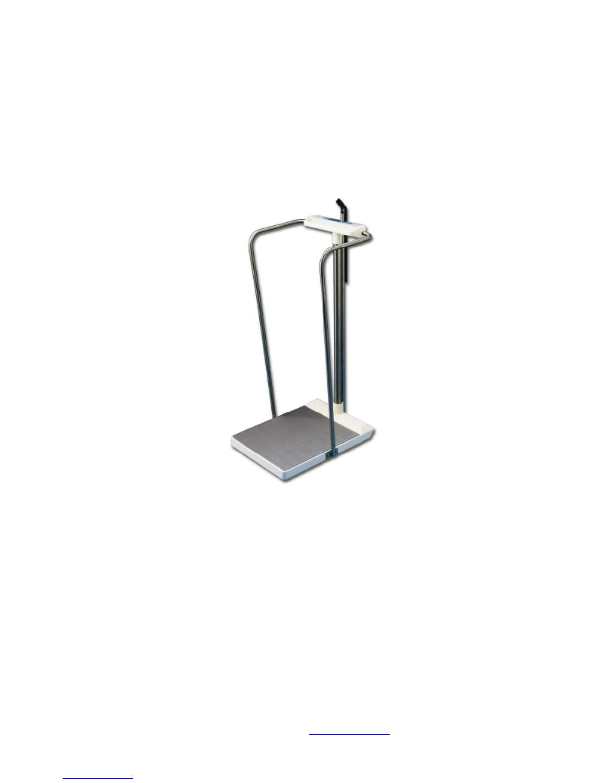
Model SR2555
Stand-On Scale
Operating Manual
Page 2

Model SR2555 Stand-On Scale Rev 991222
S
by SR Instruments, Inc.
Table of Contents
SECTION I
System Description 1.0
Intended Use 1.1
Specifications 1.2
Theory of Operation 1.3
Assembly 1.4
SECTION II
Button Functions & Basic System Operation 2.0
Special Features – Continuous Weigh/ Auto-Hold 2.1
SECTION III
Calibration 3.0
Periodic Calibration Check 3.1
ESD 3.2
Calibration Procedure 3.3
Calibration Tolerance Table 3.4
Maintenance, Care and Cleaning 3.5
Schematic Diagram 3.6
Parts List 3.7
Component Layout 3.8
Product Labeling 3.9
Page 3

Model SR2555 Stand-On Scale Rev 991222
SECTION I S S
MODEL SR2555
SYSTEM DESCRIPTION and SPECIFICATIONS
1.0 SYSTEM DESCRIPTION - The SR2555 Scale
System employs the latest in microprocessor
and load cell technology to provide accurate
and repeatable weight data. Four (4)
identically matched transducers are
strategically placed to ensure an accurate
representation of the patient's weight
regardless of weight distribution.
The low power microprocessor circuitry allows
the SR2555 to derive it’s power from six (6)
common “C” cell alkaline batteries which will
provide up to 10,000 weight readings before
needing replacement. This eliminates the
need for an external battery charger or the
danger of an A.C. power supply.
The patient’s weight is displayed on a large 2 x
24 character dot matrix L.C.D. capable of
displaying information in many different
languages. With the push of a button, weight
data may be viewed in both POUNDS and
KILOGRAMS with a displayed resolution of 0.1
LB or 100 grams.
1.1 INTENDED USE The SR2555 is designed for use
as a portable patient weighing system for
ambulatory patients only.
1.2 SPECIFICATIONS
1.2.01 Maximum Weight Capacity - The SR2555 has
a maximum weight capacity of 1000 Lbs. /
450 Kgs. This strength is due in part to the one
piece, solid aluminum cast base.
1.2.02 Platform Size –An generous standing area of
22” x 15” / 55 x 25 cm will accommodate
most all of your patients special needs.
1.2.03 Display Type - The display is a large 2 x 24
Character Dot Matrix L.C.D. with green L.E.D.
back lighting. Highly visible in all light
conditions, you may select one of 7 different
languages to view weight data : ENGLISH
FRANÇAIS ESPAÑOL DEUTSCH ITALIANO
DANSK NEDERLANDS
1.2.04 Display Resolution – The SR2555 will display
weight data in both POUNDS and KILOGRAMS
with a resolution of 0.1 Lb. or 0.1 Kg.
1.2.05 Accuracy - The accuracy of the displayed
weight is 0.1% +/- 1 digit of the displayed
resolution for calibrated range. Refer to the
Calibration Certificate supplied with the scale
for the calibrated range.
1.2.06 Zero - One button Auto-Zero
1.2.07 Memory / Recall - The feature Freezes display
and stores the data in memory. The button is
pressed once again to recall last stored
weight.
1.2.08 Auto Power Down – The system will
automatically power down in 30 seconds to
conserve battery life.
1.2.09 Averaging – An Automatic Digital Filter
samples the weight data to filter motion.
1.2.10 Power Supply - Six LR 14 (“C” cell )Alkaline
Batteries.
1.2.11 Warranty 2 YEAR LIMITED WARRANTY - Each
S scale system is manufactured
with high quality components. SR Instruments,
Inc. warrants that all new equipment will be
free from defects in material or workmanship,
under normal use and service, for a period of
two years from the date of purchase by the
original purchaser. Normal wear and tear,
injury by natural forces, user neglect and
purposeful destruction are not covered by this
warranty. Warranty service must be performed
by the factory or an authorized repair station.
Service provided on equipment returned to the
factory or authorized repair station includes
labor to replace defective parts. Goods
returned must be shipped with transportation
and/or broker charges prepaid. SR Instruments
obligation is limited to replacement of parts
which have been so returned and are
disclosed to SR Instruments satisfaction to be
defective. The provisions of this warranty clause
are in lieu of all other warranties, expressed or
implied, and of all other obligations or liabilities
on SR Instruments part and it neither assumes
or authorizes any other person to assume for SR
Instruments any other liabilities in connection
with the sale of said articles. In no event shall
SR Instruments be liable for any subsequent or
special damages. Any misuse, improper
installation or tampering, shall void this
warranty.
1.2.12 Calibration - Calibration is traceable to NIST
Standards.
1.2.13 Operating Conditions – Care has been taken
in the design of this product to provide
accurate and reliable information under
normal operating conditions. When proper
care is exercised, your scale will provide many
years of reliable service. Normal conditions for
this product would be : Temperature Range:
20oC to 30oC (68o to 85of) Humidity Range:
0%-95%. Avoid exposure to high pressure
water or steam.
1.2.14 Transport and Storage – To maintain proper
operation of this instrumentation transport and
storage conditions should not vary outside the
following conditions: Humidity: 0% to 99%,
Ambient Temp:-200C to +500C
1.2.15 Patient Applied Part Classification – TYPE B
1.2.16 Accessories – The SR2555 is available with
optional handrails for 3-Sided support (part no.
FG3070) and a Height Gauge (part no. 3086)
107 – 203 cm / 42” – 80”.
Page 1
Page 4
Model SR2555 Stand-On Scale Rev 991222
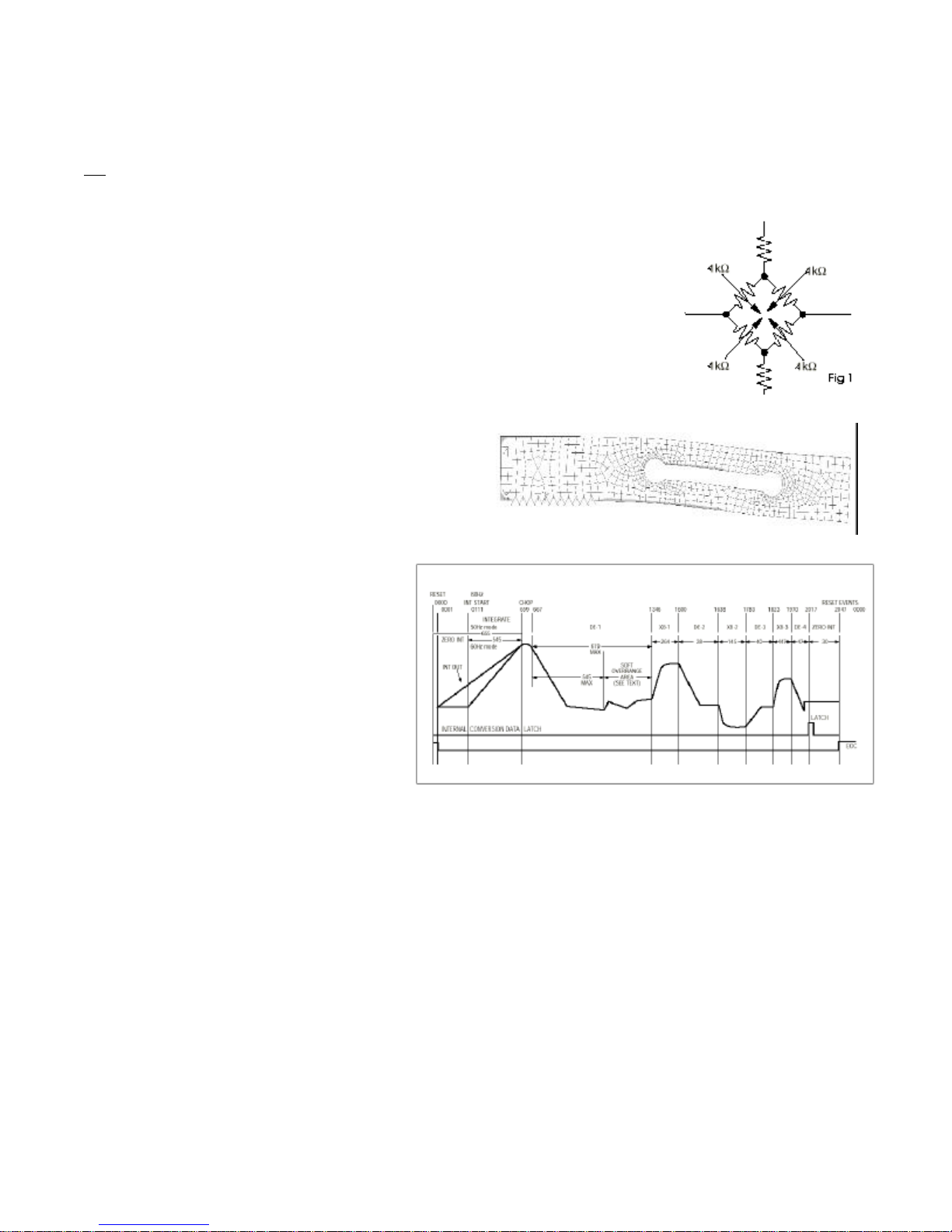
Figure 2. Force Cell bending with applied weight (displacement exaggerated for clarity)
SECTION I S S
SR2555 Theory of Operation
1.3 The SR2555 patient weighing system is a digital weigh scale. Four strain-gauge force cells convert the force of a patient’s
weight into an analog signal. This signal is amplified by a chopper-stabilized operational amplifier and converted to a digital signal
by a quad slope analog to digital converter. The digital signal is transferred to a micro-controller where it is filtered, converted to
appropriate units and displayed on a dot-matrix liquid crystal display.
The base of the SR2555 patient weighing system contains four strain gauge based
force cells (Analog board J1..4). Each cell contains four strain gauges mounted in a full
Whetstone-bridge configuration (Figure 1.) These bridges convert the physical bending of the
force cell (Figure 2.), due to the patient’s mass on the system, into minute changes in
electrical resistance. These changes in resistance produce a voltage difference across the
Whetstone Bridge, which is amplified by the chopper-stabilized operational amplifier (Analog
board U1). The amplifier is configured to current sum the output of each cell, with
potentiometers (Analog board R1, R2, R4, R5) serving to adjust the sensitivity (voltage out per
unit of weight applied) of each bridge. The offset potentiometer (Analog board R3) produces
a small current, which nulls the output of the amplifier for a n unloaded system.
The output of the operational amplifier is digitized by the quad
slope analog to digital converter (Analog board U5). The
converter integrates the analog signal onto the integrating
capacitor (Analog board C9) over a short interval. The
integrating capacitor is then discharged at a rate proportional
to the reference voltage applied to the converter
(Analog board C11 and C10). The residual voltage
on the integrating capacitor (Analog board C9) is
then multiplied by a factor of eight and again
discharged at a rate proportional to the reference
voltage (Figure 3.). The residual voltage from this
discharge is again multiplied by eight and again
discharged. The time taken to discharge the
capacitor is proportional to the voltage from the
operational amplifier, which is proportional to the
weight on the force cells. The time is stored as a
binary number in the analog to digital converter
and is transferred to the micro-controller when the
conversion is complete.
The micro-controller (Readout U1)
averages and filters the digital output of the
analog to digital converter, subtracts the value
saved during the system tare operation and scales
the filtered output to the appropriate units (Kg or
Lb.) then displays the result on the dot-matrix liquid crystal display. The micro-controller performs a rolling average of two seconds
of data for continuous weigh and, for AutoHold, the micro-controller averages two seconds of data, minimum, before locking in
on the reading. If the data variance is greater than 0.1% in the AutoHold mode, the micro-controller will reset the filter and start a
new averaging period.
The micro-controller can be placed in a calibration mode (Readout J5), where the system can be re-calibrated. In the
calibration mode, the result of the weigh operation is scaled to match the value entered by the decimal keypad. This new
calibration factor is then stored in the non-volatile memory (Analog board U4).
Figure 3. Analog to digital converter timing diagram (from Maxim MAX132 data sheet).
Page 2
Page 5

Model SR2555 Stand-On Scale Rev 991222
1.4 ASSEMBLY
IMPORTANT: All of the scale systems
are calibrated at our factory as a
complete system. Components should
not be interchanged with other
systems. To assure optimal accuracy
and reliability, make sure the serial
numbers on the readout (2) and the
base (1) match.
1. Insert mast(5) into base assembly
(1) as shown.
2. Remove the 4 set screws (10) from
the base collar and apply loctite
®
to all set screws
3. Make sure the mast is seated firmly
in the base assembly. Re-install the
set screws and tighten.
4. Slide the cable from the display
assembly (2) down the mast (5)
and out through the base.
5. Insert the mast (5) into the collar of
the display assembly (2) and seat
firmly. Turn the readout assembly
(2) so that it is aligned with the
base assembly.
6. Apply loctite® to all set screws and
tighten display assembly in place.
7. Plug the display assembly cable
into the base assembly as shown
and secure the cable in place with
the strain relief clamp provided at
the bottom of the collar in the
base assembly. Make sure the
excess cable is fed back into the
mast (5) before tightening the
strain relief clamp.
8. Remove the battery cover (8) and
install the 6 “LR14” (C cell) batteries
provided. Replace the cover.
OPTIONAL HANDRAILS –
Install the handrails with the hardware
provided. Be sure to use the lock
washers (12) and apply loctite® to all
screws.
1. Attach the LEFT and RIGHT handrails (3,4) to the bottom of the readout assembly (2) first and then to the base (1)
as shown.
OPTIONAL HEIGHT BAR –
1. Insert the Height Bar (6) from the top making sure it is seated firmly at the base.
2. Align the top extension perpendicular to the readout
3. Apply loctite® to all set screws and tighten in place
Page 3
Page 6

Model SR2555 Stand-On Scale Rev 991222
))
0.0
/
SECTION II S S
2.0 BUTTON FUNCTIONS and BASIC OPERATION
2.0.1 LANGUAGE SELECT
..
))
))
The language button allows you to select one of the following languages to display weight data
and system messages –
ENGLISH FRANÇAIS ESPAÑOL DEUTSCH ITALIANO DANSK NEDERLANDS
Procedure for Weighing Standing Patients
2.0.2 ZERO – Press the “0” button to set the system tare to ZERO. The displayed message will indicate
“PLEASE WAIT – HANDS OFF” / “ZEROING SCALE”. Make sure that nothing is in contact with the scale
system during this process. In a few seconds the display will indicate “WEIGHT = 0.0 POUNDS” (or
KILOGRAMS).
The Patient may now step up onto the scale platform to view the weight data.
NOTE: It is recommended that you press “0” before each weighing to assure optimal accuracy.
2.0.3 WEIGH - If the display shuts off before you are able to view the weight data, simply press the “WEIGH”
button to wake the display and view the patient’s weight. The display will indicate “CURRENT WEIGHT
= XXX.X POUNDS“ (or KILOGRAMS).
W
2.0.4 MEMORY/RECALL - Pressing the “MEMORY/RECALL” button will freeze the displayed weight data and
store it away in memory. To recall the stored weight data, wait until the system has automatically shut
off then press the “MEMORY/RECALL” button. The display will indicate “LAST WEIGHT = XXX.X
POUNDS” (or KILOGRAMS).
Pressing the “0.0” button will clear the last stored weight from memory.
2.0.5 POUNDS / KILOGRAMS -Weight data may be viewed in either POUNDS or KILOGRAMS. Pressing the
button allows you to switch between display modes quickly and easily.
LB
2.0.6 IMPORTANT – Be sure not to touch the patient or the scale during the weighing process. By design,
Both modes will display patient weight with 0.1 units of resolution. ( 0.1 Lb. or 0.1 Kg. )
the entire scale assembly is weight sensitive so that the patient may use the structure for support
should their condition dictate.
Page 4
Page 7

Model SR2555 Stand-On Scale Rev 991222
0.0
SECTION II S S
2.1 Special Features
CONTINUOUS WEIGH and AUTO-HOLD
The SR2555 has the capability of displaying patient weight in two different ways.
2.1.01 CONTINUOUS WEIGH - When the SR2555 is shipped it comes in the Continuous Weigh Mode. This means
that when the patient is being weighed, the weighing surface remains ACTIVE and the display may show
variations depending on the movement of the patient. To LOCK the displayed reading you must press
the "MEMORY/RECALL" button. This will also store the weight data in memory if you wish to recall it.
2.1.02 AUTO-HOLD - The Auto-Hold Mode will automatically LOCK the displayed weight data and store it in
memory as the last weight. The Auto-Hold Mode is activated as follows:
Press and Hold the "MEMORY/RECALL" button for approximately 5 sec. until the display indicates
"AUTO-HOLD ENABLED" then release the button.
To return to the Continuous Weigh Mode simply repeat the same procedure. The display will indicate
"CONTINUOUS WEIGH ENABLED".
2.1.03 Procedure for Weighing Patients in AUTO-HOLD mode
1. Press the "0" button to set the zero.
2. Position the patient on to the scale.
W
If the display turns off before you view the weigh data or if you wish to re-weigh the patient simply press the "WEIGH"
button once again while the patient is still on the scale.
IMPORTANT:
3. When the patient's motion has stabilized, press the "WEIGH" * button.
* Note: In the Auto-Hold mode you MUST press the "WEIGH" button to display the weight.
If after the display turns off you wish to recall the last stored weight you MUST press the
"MEMORY/RECALL" button FIRST. Otherwise the last stored weight will be reset.
Page 5
Page 8

Model SR2555 Stand-On Scale Rev 991222
1
2
3
6987045
SECTION III
SS
3.0 CALIBRATION
3.1 Periodic Calibration Check - IMPORTANT : The following calibration procedure should only be performed by
qualified service personnel. The SR2555 load cell, itself, has no user serviceable components and should not be
tampered with for any reason.Re-calibration is generally not required, but should be verified periodically to ensure
accuracy. Our recommendation for calibration check is at least once every 12 months or as your maintenance
policy requires.
3.2 ESD – The integrated circuits and semiconductors on the printed circuit boards may be damaged by electrostatic
discharge (ESD). Be sure to use proper handling precautions at all times.
3.3 CALIBRATION PROCEDURE - NOTE: Make sure that nothing is in contact with the scale system during this procedure.
Be sure to remove your hands from the system when noting the displayed calibration results.
1. The Calibration Slide Switch (J5) is located on the bottom side of the display
P.C. board. Expose the Calibration Jumper by removing the two (2) screws on
the bottom side of the display housing and lifting the face plate up and off.
2. Move the calibration switch to the CAL ON position. The display will read
"CALIBRATION MODE".
3. When in the Calibration Mode, press "T" button to zero the display.
4. Place known calibrated weights on to the weighing surface and compare it to
the displayed reading. Note: For best results use around 200 lbs / 90 kgs of
T
7. Press the “SAVE” button to save the calibration data. The display will indicate “SAVING CALIBRATION” – “HANDS OFF / PLEASE
WAIT”. DO NOT touch the scale system during this process. NOTE: If you make an error of wish to abort your changes, simply
move the calibration switch to the CAL OFF position. DO NOT PRESS “SAVE”
8. Move the calibration switch to the CAL OFF position.
9. Re-assemble the display electronics.
known calibrated weights.
5. Use the Key Pad to enter the proper weight. The displayed value should be
within 0.1% of the calibrated weight plus or minus 1 digit of reading.
6. Remove the weight and repeat steps 3 – 5 to be sure of consistent results.
3.4 CALIBRATION TOLERANCE TABLE
LOW APPLIED HIGH
LIMIT LOAD LIMIT
99.9 100.0 100.1
199.8 200.0 200.2
299.7 300.0 300.3
399.6 400.0 400.4
499.5 500.0 500.5
599.4 600.0 600.6
699.3 700.0 700.7
799.2 800.0 800.8
899.1 900.0 900.9
999.0 1000.0 1001.0
3.5 MAINTENANCE, CARE and CLEANING - The readout and transducer housing for the SR2555 Scale System is made of
an epoxy powder-coated aluminum casting with stainless steel riser posts. You need only exercise caution when
cleaning the display window of the electronics as this is made of clear polyester . We recommend mild soap and
water for general cleaning and disinfecting.
3.5.01 WARNING: DO NOT use pressurized water or steam. The scale system contains microprocessor circuitry and strain
gage sensors that may be adversely affected by exposure to such an environment.
3.5.02 STORAGE – If storing this equipment for periods longer than 3 months remove the batteries. Observe storage
conditions in section 1.2.14
3.5.03 BATTERY REPLACEMENT – When battery replacement is needed the display will indicate “CHANGE BATTERIES”. When
replacing batteries ALWAYS replace all six batteries at the same time. Use only LR 14 or “C” cell type alkaline
batteries.
Page 6
Page 9

Model SR2555 Stand-On Scale Rev 991222
SECTION III
SS
3.6 SCHEMATIC DIAGRAM
Page 7
Page 10

Model SR2555 Stand-On Scale Rev 991222
SECTION III
3.7 PARTS LIST
No_ Description Quantity per Position Position 2 Position 3
EPCB980811C PC BOARD 980811C 1
FCKMDL-8S-AS KYCON MINI-DIN 90DEG PCB 8PIN 1 J5
EV50K89PR 50K POTENTIOMETER 89PR50K 5 R1,R2,R3,R4 ,R5
ER21005QF 100 OHM 1/4 WATT 5% RESISTOR 2 R30,R31
ER31005QF 1K 1/4 WATT 5% RESISTOR 5 R22,R23,R24 ,R25,R26
ER51005QF 100K 1/4 WATT 5% RESISTOR 4 R16,R18,R19 ,R20
ER31001EJ 1K 1/8 WATT 1% J RESISTOR 8 R7,R8,R9,R1 0,R11,R12, R13,R17
ER51003EJ 100K 1/8 WATT 1% J RESISTOR 1 R21
ER54991EJ 499K 1/8 WATT 1% J RESISTOR 2 R6,R34
ER43921EJ 39.2K 1/8 WATT 1% J RESISTOR 2 R15, R14
ER46041EJ 60.4K 1/8 WATT 1% J RESISTOR 1 R33
ER43011EJ 30.1K 1/8 WATT 1% RESISTOR 2 R32,R35
ER41005QF 10K 1/4 WATT 5% RESISTOR 3 R27,R28,R29
EC710RE016 10MFD #UVX1C100MDA (NICHICON) 4 C1,C2,C3, C4
EC510RM050 .1MFD #R68104J63B (NISSEI) 4 C10,C11,C6, C5
EC210AP 100PF POY CAP.#09WX7747 1 C7
EC510RF 0.1MFD #SR205C104KAA (AVX) 1 C8
ECP3272 .0027MFD RADIAL, POLY 50V 1 C9
EC547J63 .47MFD #168474J63F (MALLORY) 1 C12
ETBSS110 TRANSISTOR (FAIRCHILD)MOS-FET 1 Q1
EITSC7652C IC #TC7652CPA 1 U1
ET55RP500 REGULATOR (TELCOM) 5V 1 U2
EIMAX660CP IC #MAX660CPA 1 U3
EINM24C02EN IC #NM24C02EN 1 U4
EIMAX132CN IC #MAX132CNG (MAXIM) 1 U5
EITLE2426C IC #TLE2426CLP (TEXAS INSTR.) 1 U6
EXSE3331 CRYSTAL 96.000KHz (DIGI-KEY) 1 X1
ED1N5817 DIODE 1N5817 1 D1
ESRUE090 SWITCH, POLY (RAYCHEM) #RUE090 1 F1
ED1N914 DIODE 1N914 0
EIDIP8 SOCKET 8 PIN (BURNDY) 4
No_ Description Quantity per Position Position 2 Position 3
EPCB980812C P.C.BOARD S/M (EUROPE) 1
ECV1H104KBW .1 MFD 50 V CERAMIC CHIP CAP 18 C1,THRU C18
ER1K18W5 1.0K 1/8W 5% RESISTOR-SURFACE 27 R31R33R35R36R32 R34R17R18R37R39,R10 R15R16R19R24R23R38R9
ER10018W5 100 OHM 1/8W 5% RESISTOR SURFA 2 R40,R41
ER1M18W5 1.0MEG 1/8W 5% RESISTOR-SURFAC 7 R45R44R43 R46R42R47 R48
ER10OHM18W5 10 OHM 1/8W 5% RESISTOR-SURFAC 1 R1
ER100K18W5 100K 1/8W 5% RESISTOR-SURFACE 14 R11R14,R8 R13R12R6R5 R7R4R3R49R50R51R52
ER770101 RESISTOR NETWORK 100K #770-101 1 R60
EC722SM016 22MFD #PCS3226CT SURFACE MT. 2 C19,C20
ETNDS9955 SM XITSOR NDS9955CT(FAIRCHILD 2 Q1A,Q1B
EICHD64F3437 HD64F3437FLH15 Hitatchi Micro 1 U1
EIMAX3320ACAP Maxim MAX3320ACAP 1 U2
EIMAX662ACSA Maxim MAX662ACSA 1 U3
EIADP3367AR IC - LOW DROPOUT LINEAR VOL. 1 U4
ELBRT1209 BUZZER #BRT1209-PF12 1 SPK1
TSW10913TSRE TSW109-13-TS-RE,13 PIN 90'HEAD 1
FCTSW11312 TERMINAL STRIP TSW113-12-T-S-R 1 J6
ESMMS12 SWITCH #MMS12 (ALCO) 2 SW-1,SW-2
ESP8060S SWITCH,PANASONIC #P8060S-ND 1 SW3
FCCLH108FD TERMINAL STRIP CLH-108-F-D-TE 1
EXPBRC4 #PBRC-4.00B CERAMIC RESONATOR 1 X1
EIDIP16 SOCKET,16 PIN DILB-16P-223T 1
SS
0 R27,R26,R28 R30R29R25 R21R20R22
Page 8
Page 11

Model SR2555 Stand-On Scale Rev 991222
SECTION III
SS
3.8 COMPONENT LAYOUT
Page 9
Page 12

Model SR2555 Stand-On Scale Rev 991222
3.9 PRODUCT LABELING
Page 13

Model SR2555 Stand-On Scale Rev 991222
Tel: 716.693.5977 Fax: 716.693.58 54 www.srscales.com email: sri@srinstruments.com
S
By SR Instruments, Inc.
600 Young Street, Tonawanda, NY 14150
 Loading...