

Page 1

Model SR755KG Series Wheelchair Scale
Operating and Service Manual - S/N 1913+
Part No.: MAN755KG_100929 Page 1 of 16
by S Instruments, Inc.
Model
SR755KG
Wheelchair Scale
Operating and Service
SInstruments, Inc.
Tel: 716-693-5977 Fax: 716-693-5854 URL: www.srscales.com
email: sri@srinstruments.com
Manual
Serial Numbers: 1913+
, 600 Young Street, Tonawanda, NY 14150
Copyright 2010 SInstruments, Inc.
Page 2

Model SR755KG Series Wheelchair Scale
Operating and Service Manual - S/N 1913+
Part No.: MAN755KG_100929 Page 2 of 16
TABLE OF CONTENTS
TABLE OF FIGURES ......................................................................................................................2
PACKING CHECKLIST – MODEL SR755KG ...........................................................................3
ASSEMBLY.......................................................................................................................................4
REPLACEMENT PARTS AND ACCESSORIES ........................................................................5
SYSTEM DESCRIPTION AND INTENDED USE .......................................................................5
MAINTENANCE AND CLEANING ..............................................................................................6
STORAGE AND TRANSPORTATION ........................................................................................6
SPECIFICATIONS...........................................................................................................................7
BUTTON FUNCTIONS ...................................................................................................................8
BASIC SYSTEM OPERATION ......................................................................................................8
BATTERY REPLACEMENT .........................................................................................................9
THEORY OF OPERATION .........................................................................................................10
CALIBRATION ..............................................................................................................................11
INITIALIZATION .........................................................................................................................12
TROUBLESHOOTING .................................................................................................................13
WARRANTY...................................................................................................................................14
NOTES .............................................................................................................................................15
TABLE OF FIGURES
Figure 1: Assembly Diagram ......................................................................................................... 4
Figure 2: Location of Mast Pipe Set Screws and Display Cable Connection ............................ 4
Figure 3: Leveling Feet Installation .............................................................................................. 5
Figure 4: Button Display ................................................................................................................ 8
Figure 5: Battery Compartment .................................................................................................... 9
Figure 6: Calibration Button Diagram ....................................................................................... 11
Figure 7: Location of Internal Initialization Buttons ................................................................ 12
SInstruments, Inc.
Tel: 716-693-5977 Fax: 716-693-5854 URL: www.srscales.com
email: sri@srinstruments.com
, 600 Young Street, Tonawanda, NY 14150
Copyright 2010 SInstruments, Inc.
Page 3

Model SR755KG Series Wheelchair Scale
Operating and Service Manual - S/N 1913+
Part No.: MAN755KG_100929 Page 3 of 16
PACKING CHECKLIST – Model SR755KG
Stand-On Scale
DESCRIPTION QUANTITY
√
BASE ASSEMBLY SR755KG: 61 cm x 71 cm (24 in x 28 in) * 1 ea
MAST PIPES 2 ea
DISPLAY UNIT* with CABLE 1 ea
PACKAGE OF FOUR (4) LEVELING FEET 1 ea
PACKAGE OF SIX (6) “D” CELL BATTERIES 1 ea
1/8” ALLEN WRENCH 1 ea
QC INSPECTION SHEET 1 ea
CALIBRATION CERTIFICATE 1 ea
WARRANTY CARD 1 ea
MANUAL 1 ea
LOCTITE®
1 ea
PACKING CHECKLIST – Model SR755LKG
DESCRIPTION QUANTITY
√
BASE ASSEMBLY SR755LKG: 71 cm x 71 cm (28 in x 28 in) * 1 ea
MAST PIPES 2 ea
DISPLAY UNIT* with CABLE 1 ea
PACKAGE OF FOUR (4) LEVELING FEET 1 ea
PACKAGE OF SIX (6) “D” CELL BATTERIES 1 ea
1/8” ALLEN WRENCH 1 ea
QC INSPECTION SHEET 1 ea
CALIBRATION CERTIFICATE 1 ea
WARRANTY CARD 1 ea
MANUAL 1 ea
LOCTITE®
*Note: All Set Screws are shipped in place on scale
SInstruments, Inc.
Tel: 716-693-5977 Fax: 716-693-5854 URL: www.srscales.com
email: sri@srinstruments.com
1 ea
, 600 Young Street, Tonawanda, NY 14150
Copyright 2010 SInstruments, Inc.
Page 4

Model SR755KG Series Wheelchair Scale
Operating and Service Manual - S/N 1913+
Part No.: MAN755KG_100929 Page 4 of 16
ASSEMBLY
STEP 1: Unpack the scale system and check parts
against the PACKING CHECKLIST. If there are any
missing or damaged parts, please call the Service Hotline:
1-800-654-6360.
STEP 2: (Figure 1) Verify that the serial number on the
Display Unit (1) matches that on the B ase Assem bly (3).
1
STEP 3: (Figure 1) Attach the Mast Pipes (2) to
the Display Unit (1), feeding the cable down
2
through the left pipe. Securely tighten the set
screws in the display casting collars using a small
Pipe for Cable
amount of Loctite
STEP 4: Position the Mast Pipes into the Base
Assembly as shown, while feeding the display
cable through the left hole.
# PART NAME
Display Unit
1
Mast Pipes
2
Base Assembly
3
Battery Compartment Cover
4
Mast Pipe Set Screws
5
Display Cable Connector
6
Leveling Feet
7
®.
3
Figure 1: Assembly Diagram
STEP 6: (Figure 2) Attach the Display
Cable Connector (6) to its mate in the Base
Assembly. Slide the extra cable back up into
the Mast Pipe
STEP 7: Install the six (6) “D” cell
batteries as indicated on the Battery
Compartment Cover label. Tightly close the
cover.
STEP 5: (Figure 2) Gently rest the scale on its
side and open the Battery Compartment Cover (4)
located in the Base Assembly between the wheels.
Make sure the Mast Pipes are seated against the
bottom stops and securely tighten the Mast Pipe Set
Screws (5) using a small amount of Loctite®.
6
5
Figure 2: Location of Mast Pipe Set Screws and Display
Cable Connection
4
SInstruments, Inc.
Tel: 716-693-5977 Fax: 716-693-5854 URL: www.srscales.com
email: sri@srinstruments.com
Continued next page
, 600 Young Street, Tonawanda, NY 14150
Copyright 2010 SInstruments, Inc.
Page 5

Model SR755KG Series Wheelchair Scale
Operating and Service Manual - S/N 1913+
Part No.: MAN755KG_100929 Page 5 of 16
ASSEMBLY cont’d
STEP 8: (Figure 3) Attach Leveling Feet (7) (separate package
provided) to each of the four (4) corners of the Base Assembly.
Screw the leveling feet approximately 1/2 inch into the hole of each
of the four (4) transducer cells. Note: Leveling feet must be in
place to operate the scale properly.
STEP 9: Return the scale to the upright position. Adjust
Leveling Feet to ensure scale will sit level on the floor.
7
Figure 3: Leveling Feet Installation
REPLACEMENT PARTS and ACCESSORIES
Part # Description
CA4886 Display Label
MF2284T52 Leveling Foot
SYSTEM DESCRIPTION and INTENDED USE
SYSTEM DESCRIPTION
The SR755KG Wheelchair Scale System employs the latest in microprocessor and load cell
technology to provide accurate and repeatable weight data. Four (4) identically matched
transducers are strategically placed to ensure an accurate representation of the patient’s weight.
The low power microprocessor circuitry allows the SR755KG to derive its power from six (6)
common “D” cell batteries that will provide up to 10,000 weight readings before needing
replacement. This eliminates the need for an external battery charger or the danger of an AC
power supply cord on a portable scale.
The patient’s weight is displayed on a 16-character dot matrix LCD. With a push of a button,
weight data may be viewed, in either pounds or kilograms, with a displayed resolution of 0.1 for
each.
SInstruments, Inc.
Tel: 716-693-5977 Fax: 716-693-5854 URL: www.srscales.com
email: sri@srinstruments.com
Continued next page
, 600 Young Street, Tonawanda, NY 14150
Copyright 2010 SInstruments, Inc.
Page 6

Model SR755KG Series Wheelchair Scale
Operating and Service Manual - S/N 1913+
Part No.: MAN755KG_100929 Page 6 of 16
SYSTEM DESCRIPTION AND INTENDED USE cont’d
INTENDED USE
The SR755KG Wheelchair Scale System is specifically
designed for use as a portable patient weighing system
for ambulatory and non-ambulatory wheelchair bound
patients or those that need to be supported by a chair or
walker. Maximum weight capacity must not exceed
454 kilograms, gross weight.
MAINTENANCE and CLEANING
The SR755KG Wheelchair Scale System is
made of powder-coated aluminum casting with
stainless steel pipes. Exercise caution when
cleaning the display window as it is made of
clear polyester and can be scratched by
abrasive cleaners. Mild soap and water is
recommended for general cleaning and
disinfecting.
DO NOT use pressurized water or steam.
The scale system contains microprocessor
circuitry and strain gauge sensors that may
be adversely affected by exposure to such an
environment.
WARNING
DO NOT EXCEED
MAXIMUM WEIGHT LIMIT OF
454 KG
WARNING
STORAGE and TRANSPORTATION
STORAGE
If storing this equipment for periods longer than three (3) months, remove the batteries. To
maintain proper operation of this instrumentation, storage and transport conditions should not vary
outside the following conditions: Relative Humidity 0% to 85%, Ambient Temperature -10°C to
+50°C (14°F to 122°F).
TRANSPORTATION
To transport the SR755KG, tilt the scale back and wheel to the new location. Lower the platform
back down to the floor being careful not to shock the scale.
SInstruments, Inc.
Tel: 716-693-5977 Fax: 716-693-5854 URL: www.srscales.com
email: sri@srinstruments.com
, 600 Young Street, Tonawanda, NY 14150
Copyright 2010 SInstruments, Inc.
Page 7

Model SR755KG Series Wheelchair Scale
Operating and Service Manual - S/N 1913+
Part No.: MAN755KG_100929 Page 7 of 16
SPECIFICATIONS
MAXIMUM WEIGHT CAPACITY
PLATFORM SIZE
DISPLAY TYPE
DISPLAY RESOLUTION
ACCURACY
AUTO ZERO
AUTO POWER DOWN
HOLD
LAST WEIGHT RECALL
AVERAGING
454 kg
SR755KG: 24 in x 28 in (61 cm x 71 cm)
SR755LKG: 28 in x 28 in (71 cm x 71 cm)
16-Character dot-matrix LCD
0.1 kg
0.1% +/- 1 digit of displayed resolution for calibrated
range
One button operation
After 35 seconds
Stores displayed reading in memory
Hold button recalls last stored displayed reading
Automatic digital filter
POWER SUPPLY
CALIBRATION
OPERATING CONDITIONS
TRANSPORT and STORAGE
Six (6) “D” cell batteries
Low battery indicator on Display
Calibration is traceable to NIST standards.
Normal operating conditions for this product:
Ambient Temperature Range: 20°C to 30°C (68°F to
85°F), Relative Humidity Range: 0%-85%. Avoid
exposure to high-pressure water or steam.
Storage and transport conditions should not vary
outside the following conditions: Relative Humidity
0% to 85%, Ambient Temperature -10°C to +50°C
(14°F to 122°F). Remove batteries if storing longer
than three (3) months.
SInstruments, Inc.
Tel: 716-693-5977 Fax: 716-693-5854 URL: www.srscales.com
email: sri@srinstruments.com
, 600 Young Street, Tonawanda, NY 14150
Copyright 2010 SInstruments, Inc.
Page 8
Model SR755KG Series Wheelchair Scale
Operating and Service Manual - S/N 1913+
Part No.: MAN755KG_100929 Page 8 of 16
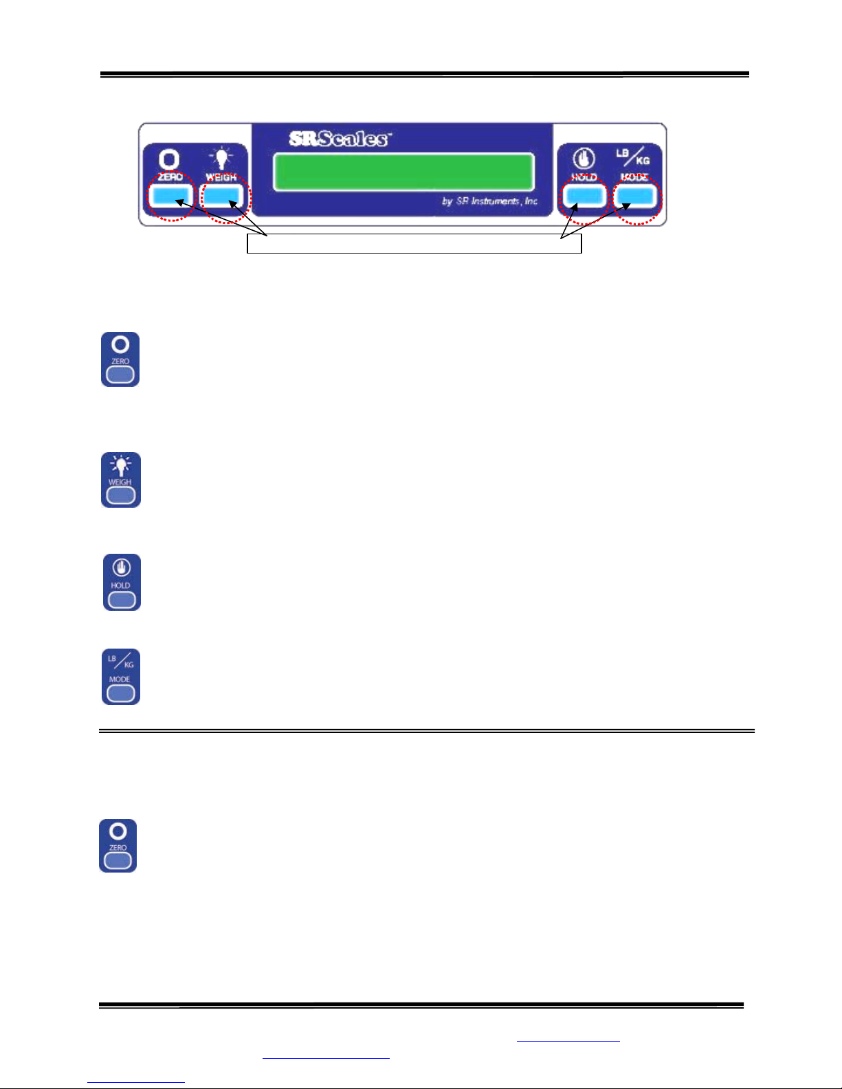
BUTTON FUNCTIONS
ERO
Z
KG).
ZERO” button is used to zero the system before placing a patient onto the scale
The “
system
WAIT
. When pressed, the display message will indicate “ZEROING” “PLEASE
” “HANDS OFF” “PLEASE WAIT”. Ensure that nothing is in contact with the
weighing su
Press box under each icon to activate command
Figure 4: Button Display
rface during this procedure. The display will read “WEIGHT 0.0 LB” (or
WEIGH
The “WEIGH” button wakes up the display and shows the patient’s weight if it should
Auto Power Down before the weighing process is done.
HOLD
The “HOLD” button freezes the displayed weight and
“HOLD
” to store the weight into memory. To recall last weight reading, press “HOLD”.
stores it away in memory. Press
LB/KG
MODE
Button is inactive.
BASIC SYSTEM OPERATION
SETTING SYSTEM ZERO / DETERMINING WHEELCHAIR WEIGHT
Make sure the sca and press the “ZERO”
button. The displa ASE WAIT” “HANDS
OFF” “PLEASE WAIT”. Ensure nothing is in contact with the sc
zeroing. In a few seconds, the display will read “WEIGHT 0.0 KG”.
le system is free and clear of any obstructions
yed message will indicate “ZEROING” “PLE
ale system while
SInstruments, Inc.
Tel: 716-693-5977 Fax: 716-693-5854 URL: www.srscales.com
email: sri@srinstruments.com
Continued next page
, 600 Young Street, Tonawanda, NY 14150
Copyright 2010 SInstruments, Inc.
Page 9
Model SR755KG Series Wheelchair Scale
Model SR755KG Series Wheelchair Scale
Operating and Service Manual - S/N 1913+
Operating and Service Manual - S/N 1913+
Part No.: MAN755KG_100929 Page 9 of 16
Part No.: MAN755KG_100929 Page 9 of 16
BASIC SYSTEM OPERATION cont’d
STEP 1: Place the empty wheelchair (with any blankets or pillows that the patient may have
with them) on the scale platform. Then press the zero button.
NOTE: The display will shut off after 35 seconds. The zero (TARE) will still be stored
in memory.
STEP 2: Remove the wheelchair from the platform. Place the patient in the wheelchair.
STEP 3: Wheel the patient with wheelchair onto the platform. Lock the patient’s wheelchair
brake to prevent movement. Press the weigh button. The display will show the patient’s weight
only.
Do not leave patient unattended on the scale platform.
CONTINUOUS WEIGH
CAUTION
In this default mode, the weighing surface remains active. Press the “HOLD” button once to lock
the displayed reading and store it in memory as the “last weight” for recall later if needed.
AUTO-HOLD
This mode is for patients unable to remain still for the weighing procedure. It locks, stores, and
displays the patient’s weight as soon as the “WEIGH” button is pressed once. Note: No weight
will be displayed until the button is pressed.
To enable this mode, BEFORE zeroing the system, press and hold the “HOLD” button for
approximately five (5) seconds until the display reads “AUTO-HOLD ENABLED”.
To return to CONTINUOUS WEIGH mode when finished, press and hold the “HOLD” button for
approximately five (5) seconds until the display reads “CONTINUOUS WEIGH”.
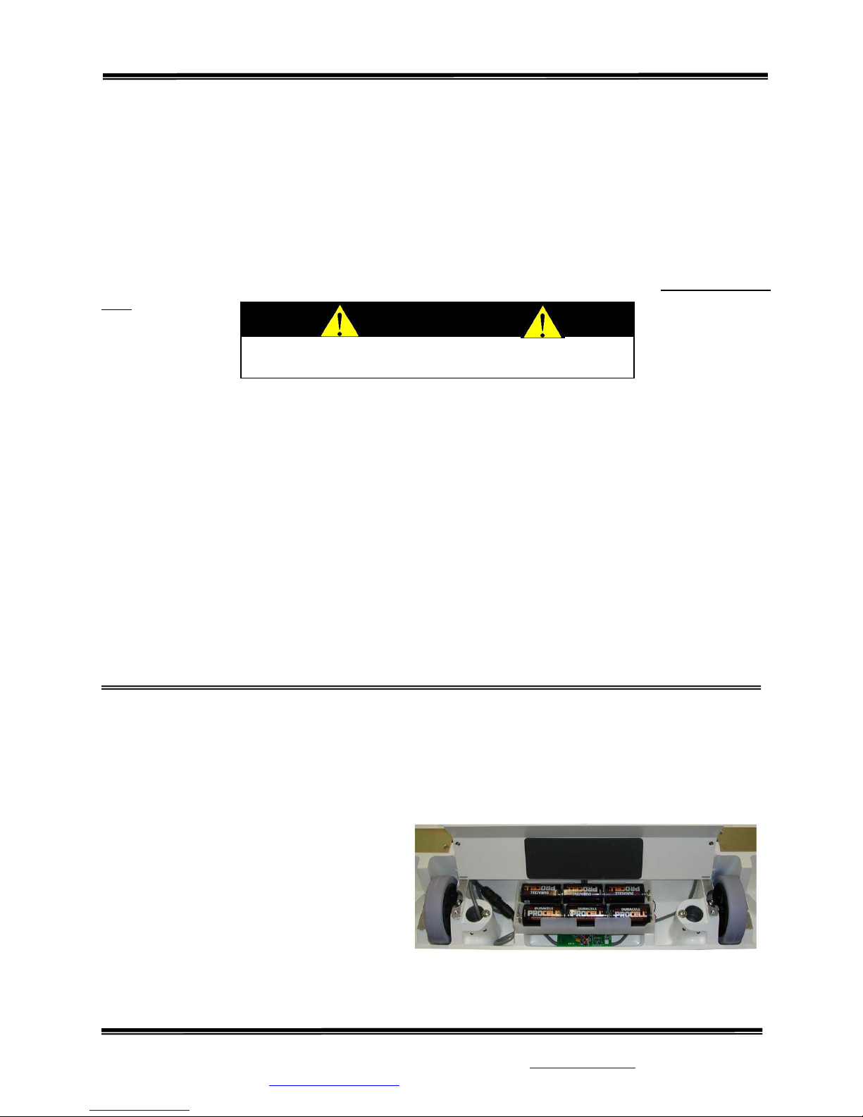
BATTERY REPLACEMENT
STEP 1: The display will read “REPLACE BATTERY”.
STEP 2: (Figure 5) Place the scale on its side and open the Battery Compartment cover located
in the bottom of the scale between the wheels.
STEP 3: Remove and replace ALL six
(6) “D” cell batteries. Refer to diagram on
the Battery Compartment cover for
placement.
STEP 4: Press the “WEIGH” button to
confirm display is working.
STEP 5: Tightly close the cover.
STEP 6: Zero the system.
SInstruments, Inc.
SInstruments, Inc.
Tel: 716-693-5977 Fax: 716-693-5854 URL: www.srscales.com
Tel: 716-693-5977 Fax: 716-693-5854 URL: www.srscales.com
email: sri@srinstruments.com
email: sri@srinstruments.com
Figure 5: Battery Compartment
, 600 Young Street, Tonawanda, NY 14150
, 600 Young Street, Tonawanda, NY 14150
Copyright 2010 SInstruments, Inc.
Copyright 2010 SInstruments, Inc.
Page 10

Model SR755KG Series Wheelchair Scale
Operating and Service Manual - S/N 1913+
Part No.: MAN755KG_100929 Page 10 of 16
THEORY OF OPERATION
SR Instruments patient weighing systems are digital scales. Strain
of an a ig
convert signal by an analog to digital converter. The digital signal is transferred to a
micro-con oller where it is filtered, converted to appropriate units, and displayed on a liquid
pplied we ht into an analog signal. This signal is amplified by an operational amplifier and
ed to a digital
tr crystal
display.
Strain-gauge force cells each contain four strain gauges mounted in a full Wheatstone-bridge
configu ysical moveme
v ss the Wheatstone-bridge, which is amplified by the opera
se
small current, which nulls the ou
ration. These bridges convert the ph nt of the force cell, due to the applied mass
n the system, into m ute changes in elec . These changes in resistance produce a
trical resistanceo in
oltage difference acro tional amplifier. The
mplifier is configured s serving to adjust the
to current sum the output of each cell, with potentiometera
nsitivity (voltage out per unit of weight applied) of each bridg e. The offset potentiometer produces a
tput of the amplifier for an unloaded sys tem.
The output of the operational amplifier is digitized by the analog to digital converter. The converter
integrates the analog signal onto the integrating capacitor over a short interval. The int
capacitor is then
The residual volta
discharged at a rate proportional to the reference voltage applied to the converter.
ge on the integrating capacitor is then multiplied by a factor and again discharged at
a rate proportional to the reference voltage. The residual voltage from this discharge is again
multiplied by a factor and again discharged. The time taken to disc harge the capacitor is proportional
to the voltage from the operational amplifier, w
hich is proportional to the applied load on the force
cells. The time is stored as a binary number in the analog to digital converter and is transferred to the
micro-controller when the conversion is complete.
The micro-controller averages and filters the digital output of the analog to digital converter, subtracts
the value saved during the system zero operation and scales the filtered output, then displays the result
on the liquid crystal display. The micro-controller perfor ms a rolling average of data for
eigh and, for AutoHold, the micro-controller averages the data before locking in on the reading. If
w
e data variance is greater t ontroller will reset the filter
th han 0.1% in the AutoHold mode, the micro-c
and start a new averaging pe
riod.
The micro controller can be placed in a calibration mode, wher
the calibra ion mode, the result of the weigh operation is scaled to match the value by adjusting the
“up” and “down” calibration buttons. This new
- e the system can be re-calibrated. In
t
calibration factor is then stored in the non-volatile
memory.
-gauge force cells convert the force
egrating
continuous
SInstruments, Inc.
Tel: 716-693-5977 Fax: 716-693-5854 URL: www.srscales.com
email: sri@srinstruments.com
, 600 Young Street, Tonawanda, NY 14150
Copyright 2010 SInstruments, Inc.
Page 11

Model SR755KG Series Wheelchair Scale
Operating and Service Manual - S/N 1913+
Part No.: MAN755KG_100929 Page 11 of 16
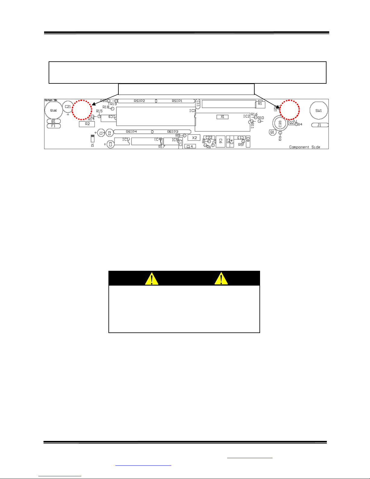
CALIBRATION
IMPORTANT
CALIBRATION CHECK Qualified service personnel only should perform this
procedure. Load cells have no user serviceable components and should not be tampered
with for any reason. Re-calibration is generally not required, but should be verified
periodically to ensure accuracy. The recommendation for calibration check is at least
once every 12 months, or as individual maintenance policy requires.
“-” “+”
Figure 6: Calibration Button Diagram
NOTE: Ensure that nothing is in contact with the scale system during this procedure. Remove
hands from the system when noting the displayed calibration results.
STEP 1: (Figure 1) Remove the two (2) screws on the bottom of the display housing. Lift the
display panel. The calibration buttons are located on the PC Board.
STEP 2: (Figure 6) Press and hold both butto
ns simultaneously
(SW5 and SW6).
STEP 3: The display will read “HOLD TO CAL” as the right hand digit
counts down to enter the CAL mode.
STEP 4: When in the CAL mode, press the “ZERO” button to zero the
display.
TEP 5: Place a known calibrated weight, traceable to NIST, onto the
S
weighing surface and compare it to the displayed reading. Note: DO
NOT USE barbell weights or calibrate to a mechanical scale.
STEP 6: Use the “-” or “+” button to make corrections to the
displayed
weight. The displayed value should be within 0.1% of the
CALIBRATIO N
TOLERANCE TABLE
LOW
LIMIT
99.9 100.0 100.
199.8 200.0 200.
299.7 300.0 300.3
399.6 400.0 400.
499.5 500.0 500.5
599.4 600.0 600.6
699.3 700.0 700.7
799.2 800.0 800.8
899.1 900.0 900.9
999.0 1000.0 1001.0
APPLIED
LOAD
HIGH
LIMIT
calibrated weight, plus or minus 1 digit of reading.
1
2
4
STEP 7: When settings are completed:
Press the “HOLD” button to SAVE the
settings or press the “WEIGH” button to
CANCEL. Both choices will EXIT the CAL
mode.
SInstruments, Inc.
Tel: 716-693-5977 Fax: 716-693-5854 URL: www.srscales.com
email: sri@srinstruments.com
CAUTION
The integrated circuits and semiconductors on
the printed circuit boards may be damaged
by electrostatic discharge (ESD). Be sure to
use proper handling precautions at all times.
, 600 Young Street, Tonawanda, NY 14150
Copyright 2010 SInstruments, Inc.
Page 12
Model SR755KG Series Wheelchair Scale
Operating and Service Manual - S/N 1913+
Part No.: MAN755KG_100929 Page 12 of 16
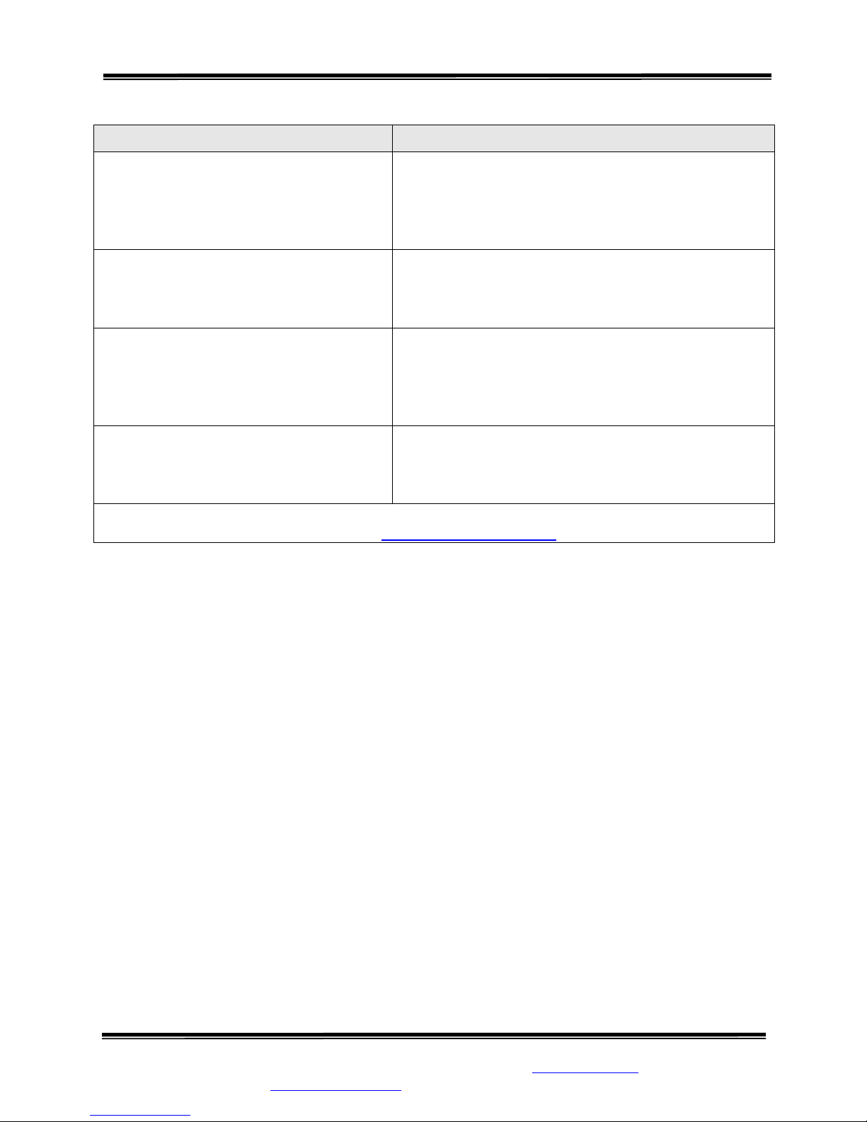
INITIALIZATION
INITIAL EDURE IZATION PROC
To be used ONLY IF REPLACING IC5 or if DISPLAY READS DOUBLE
Internal Initialization Buttons
SW5
Figure 7: Location of Internal Initialization Buttons
SW2
STEP 1: (Figure 7) Remove the two (2) screws on the bottom of the display housing. The
initialization buttons are located internally on the PC Board. Refer to PC BOARD LAYOUT
(SW2 and SW5).
STEP 2: Simultaneously press buttons indicated to initialize the system. The display will read,
“HOLD TO INIT”, and count down from 9 to 0. When the initializing is complete, the display
ill read, “INITIALIZING” and then return to the WEIGH mode. w
STEP 3: Follow the CALIBRATION procedure.
The integrated circuits and semiconductors on
the printed circuit boards may be damaged
by electrostatic discharge (ESD). Be sure to
use proper handling precautions at all times.
CAUTION
SInstruments, Inc.
Tel: 716-693-5977 Fax: 716-693-5854 URL: www.srscales.com
email: sri@srinstruments.com
, 600 Young Street, Tonawanda, NY 14150
Copyright 2010 SInstruments, Inc.
Page 13
Model SR755KG Series Wheelchair Scale
Operating and Service Manual - S/N 1913+
Part No.: MAN755KG_100929 Page 13 of 16
TROUBLESHOOTING
SYMPTOM REASON/CORRECTIVE ACTION
Inaccurate w heelchair
eight readings Scale system MUST be zeroed with empty w
BEFORE patient is positioned in the wheelc
hair and
onto the scale (see directions for BASIC SYSTEM
OPERATION).
The characters only appear on half of the
display.
Press the “WEIGH” button or remove battery.
one
Wait five seconds, then re-install the battery and try the
“WEIGH” button again.
The display lights appear to work but do
ot respond to button activa
n tion. pressed. Remove the faceplate
Button may not have “bounced” back up after being
and inspect buttons.
Make sure the rubber “boot” is not sitting too high. Reattach plate.
The display shows no reading at all. Check to make sure batteries are installed correctly (see
directions for BATTERY REPLACEMENT).
Check display cable to ensure it is connected securely.
For additional information or assistance, telephone the Service Hotline: 1-800-654-6360
or e-mail: sri@srinstruments.com
SInstruments, Inc.
Tel: 716-693-5977 Fax: 716-693-5854 URL: www.srscales.com
email: sri@srinstruments.com
, 600 Young Street, Tonawanda, NY 14150
Copyright 2010 SInstruments, Inc.
Page 14

Model SR755KG Series Wheelchair Scale
Operating and Service Manual - S/N 1913+
Part No.: MAN755KG_100929 Page 14 of 16
WARRANTY
FOUR YEAR
Each S system is ith high quality components. SR Instruments, Inc.
warrants that all new equipment will be
normal use and service, for a period of fo
purchaser. Normal wear and tear, inju ces, user neglect, and purposeful
destruction are not covered by this warranty. Wa
or an authorized repair station. Servic
authorize
with transportation and/or broker charges p ’s obligation is limited to
replacement of parts that have been so returned
satisfaction to be defective. The provi
warranties, expressed or implied
Inc.’s part, and it neither assumes nor auth ,
Inc. any other liabilities in connection w f said articles. In no event shall SR
Instruments, Inc. be liable for any subsequent
installation, or tampering, shall void t
LIMITED WARRANTY
manufactured w
free from defects in material or workmanship, under
ur (4) years from the date of purchase by the original
ry by natural for
rranty service must be performed by the factory
e
provided on equipment returned to the factory or
d repair station includes labor to re
place defective parts. Goods returned must be shipped
repaid. SR Instruments, Inc.
and are disclosed to SR Instruments, Inc.’s
si
ons of this warranty clause are in lieu of all other
, and of
all other obligations or liabilities on SR Instruments,
orizes any other person to assume for SR Instruments
ith the sale o
or special damages. Any misuse, improper
his wa
rranty.
DAMAGED SHIPMENTS
Title p age or
damage should be filed with th
asses to purchaser upon delivery to Transportation Company. Any claims for short
e delivery carrier by purchaser.
RETURN POLICY
All products being returned to SR Instruments, Inc. require a Return Goods Authorization number
(RGA). To receive an RGA, call our Technical Service Team at 716-693-5977 or toll-free in the
USA and Canada at 800-654-6360.
When inquiry is made, please supply model and serial numbers, purchase order, if the scale was
bought on contract, and reason for return.
Generally, deleted, damaged, and outdated merchandise will not be accepted for credit. A
minimum restocking charge of 15% will be assessed on return of current merchandise.
All returns are to be shipped FREIGHT PREPAID to: SR Instruments, Inc., 600 Young Street,
Tonawanda, NY 14150.
RESTOCKING FEE
• 15% fee for any scale that has been opened and used
• 10% fee for any scale returned that has been ordered incorrectly or refused delivery with
no model change
• 5% fee if an error in ordering has been made and a different model exchanged
• No fees will be charged if the scale is returned because of an error on the part of SR
Instruments, Inc.
• No returns accepted after 60 days.
SInstruments, Inc.
Tel: 716-693-5977 Fax: 716-693-5854 URL: www.srscales.com
email: sri@srinstruments.com
, 600 Young Street, Tonawanda, NY 14150
Copyright 2010 SInstruments, Inc.
Page 15

Model SR755KG Series Wheelchair Scale
Operating and Service Manual - S/N 1913+
Part No.: MAN755KG_100929 Page 15 of 16
NOTES
SInstruments, Inc.
Tel: 716-693-5977 Fax: 716-693-5854 URL: www.srscales.com
email: sri@srinstruments.com
, 600 Young Street, Tonawanda, NY 14150
Copyright 2010 SInstruments, Inc.
Page 16

Model SR755KG Series Wheelchair Scale
Operating and Service Manual - S/N 1913+
Part No.: MAN755KG_100929 Page 16 of 16
By SInstruments, Inc.
Precision & Technology in
SInstruments, Inc.
Tel: 716-693-5977 Fax: 716-693-5854 URL: www.srscales.com
email: sri@srinstruments.com
Perfect Balance
, 600 Young Street, Tonawanda, NY 14150
Copyright 2010 SInstruments, Inc.
®
 Loading...