

Model SR725 Series Wheelchair Scale System
Operating and Service Manual - S/N 4068+
Part No. MAN725_100928 Page 1 of 16
by S Instruments, Inc.
Model
SR725 / SR725L
Wheelchair Scale System
Operating and Service
Manual
Serial Numbers: 4068+
SInstruments, Inc.
Tel: 716-693-5977 Fax: 716-693-5854 URL: www.srscales.com
email: sri@srinstruments.com
, 600 Young Street, Tonawanda, NY 14150
Copyright 2010 SInstruments, Inc.

Model SR725 Series Wheelchair Scale System
Operating and Service Manual - S/N 4068+
Part No. MAN725_100928 Page 2 of 16
TABLE OF CONTENTS
TABLE OF FIGURES ......................................................................................................................2
PACKING CHECKLIST SR725 .....................................................................................................3
PACKING CHECKLIST SR725L ..................................................................................................3
ASSEMBLY.......................................................................................................................................4
REPLACEMENT PARTS AND ACCESSORIES ........................................................................5
SYSTEM DESCRIPTION AND INTENDED USE .......................................................................6
MAINTENANCE AND CLEANING ..............................................................................................7
STORAGE AND TRANSPORTATION ........................................................................................7
SPECIFICATIONS...........................................................................................................................8
BUTTON FUNCTIONS ...................................................................................................................9
BASIC SYSTEM OPERATION ......................................................................................................9
BATTERY REPLACEMENT .......................................................................................................10
THEORY OF OPERATION .........................................................................................................11
CALIBRATION ..............................................................................................................................12
INITIALIZATION .........................................................................................................................13
TROUBLESHOOTING .................................................................................................................14
WARRANTY...................................................................................................................................15
TABLE OF FIGURES
Figure 1: Assembly Diagram ....................................................................................................... 4
Figure 2: Display Unit Cable Connection ................................................................................... 4
Figure 3: Display Unit .................................................................................................................... 5
Figure 4: Battery Cover Display Unit ......................................................................................... 5
Figure 5: Ramp Locking Pin ........................................................................................................ 5
Figure 6: Mast Wing Nut ............................................................................................................. 7
Figure 7: Button Display .............................................................................................................. 9
Figure 8: Battery Compartment Cover Panel Screw .............................................................. 10
Figure 9: Calibration Button Diagram ..................................................................................... 12
Figure 10: Location of Internal Initialization Button ................................................................ 13
SInstruments, Inc.
Tel: 716-693-5977 Fax: 716-693-5854 URL: www.srscales.com
email: sri@srinstruments.com
, 600 Young Street, Tonawanda, NY 14150
Copyright 2010 SInstruments, Inc.
Model SR725 Series Wheelchair Scale System
Y
Y
Operating and Service Manual - S/N 4068+
Part No. MAN725_100928 Page 3 of 16
PACKING CHECKLIST SR725
Wheelchair Scale System
DESCRIPTION QUANTIT
√
BASE ASSEMBLY: 32 in x 32 in (81 cm x 81 cm)
WITH ATTACHED MAST PIPE AND RAMP
DISPLAY UNIT 1 ea
PACKAGE OF SIX (6) “D” CELL BATTERIES 1 ea
CALIBRATION CERTIFICATE 1 ea
WARRANTY CARD 1 ea
MANUAL 1 ea
1 ea
PACKING CHECKLIST SR725L
Wheelchair Scale System
DESCRIPTION QUANTIT
√
BASE ASSEMBLY: 32 in x 36 in (81 cm x 91 cm)
WITH ATTACHED MAST PIPE AND RAMP
DISPLAY UNIT 1 ea
PACKAGE OF SIX (6) “D” CELL BATTERIES 1 ea
CALIBRATION CERTIFICATE 1 ea
WARRANTY CARD 1 ea
MANUAL 1 ea
1 ea
SInstruments, Inc.
Tel: 716-693-5977 Fax: 716-693-5854 URL: www.srscales.com
email: sri@srinstruments.com
, 600 Young Street, Tonawanda, NY 14150
Copyright 2010 SInstruments, Inc.
Model SR725 Series Wheelchair Scale System
Operating and Service Manual - S/N 4068+
Part No. MAN725_100928 Page 4 of 16
ASSEMBLY
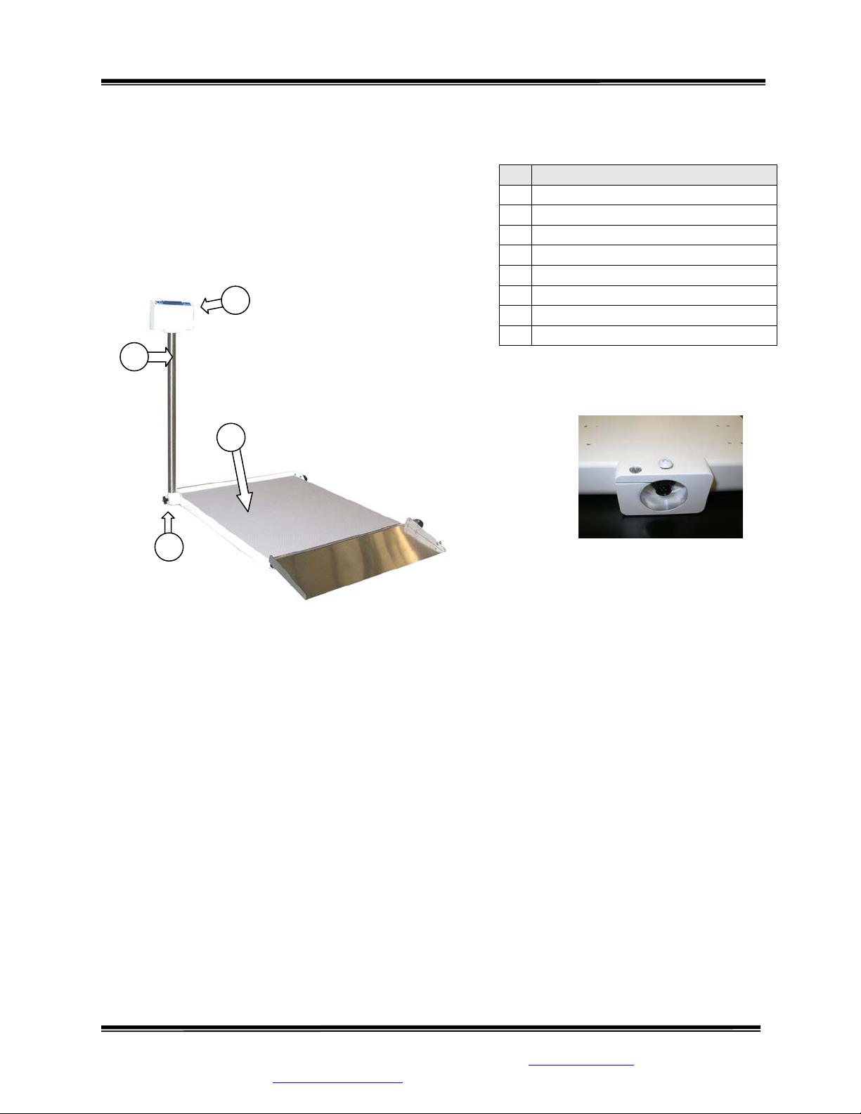
STEP 1: Unpack the scale system and check parts against
the PACKING CHECKLIST. If there are any missing or
damaged parts, please call the Service Hotline at: 1-800654-6360.
STEP 2: Verify that the serial number on the Display
Unit (1) matches that on the Base A ssembly (3 ).
1
2
Figure 1: Assembly Diagram
# PART NAME
Display Unit
1
Mast Pipe
2
Base Assembly
3
Mast Wing Nut
4
Battery Compartment Cover
5
Ramp
6
Ramp Locking Pin
7
Transport Wheels
8
3
4
Figure 2: Display Unit
Cable Connection
STEP 3: (Figure 1) Lay the Base Assembly (3) with the attached Mast Pipe (2) on the floor.
STEP 4: Loosen the Mast Wing Nut (4) to unlock the Mast Pipe. Pull the Mast Pipe out and away
from the scale to free it from the internal locking pin and swing it up until the Mast Pipe is
perpendicular to the platform. Gently push the Mast Pipe against the Base Assembly, engaging it
in the lock position.
STEP 5: Tighten the Mast Wing Nut to secure the Mast Pipe in place.
STEP 6: (Figure 2) Connect the display cable (pre-installed in Mast Pipe) into its mate located
in the base of the Display Unit. Secure the connection by giving the attached lock ring a 1/4 turn
to the right.
Continued next page
SInstruments, Inc.
Tel: 716-693-5977 Fax: 716-693-5854 URL: www.srscales.com
email: sri@srinstruments.com
, 600 Young Street, Tonawanda, NY 14150
Copyright 2010 SInstruments, Inc.
Model SR725 Series Wheelchair Scale System
Operating and Service Manual - S/N 4068+
Part No. MAN725_100928 Page 5 of 16
ASSEMBLY Cont’d
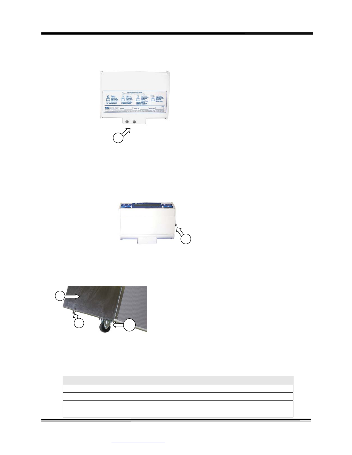
Figure 3: Display Unit
5
STEP 7: (Figure 3) Insert the mast pipe into the display post mount assem bly. Tighten the 10-32 x 3/8”
Phillips screw(s) and ¼” x 20 x 3/8” Phillips screw (5).
STEP 8: Unscrew and remove the Battery Compartment Cover (6). Install the six (6) “D” cell batteries
as indicated on the plastic battery cradle. Replace the cover (Figure 4).
Figure 4: Battery Cover Display Unit
6
STEP 9: Adjust leveling feet, located in each of the four corners of the underside of the Base
Assembly, to ensure that the scale will sit level on the floor. Note: Leveling feet m ust be in plac e to
operate the scale properly.
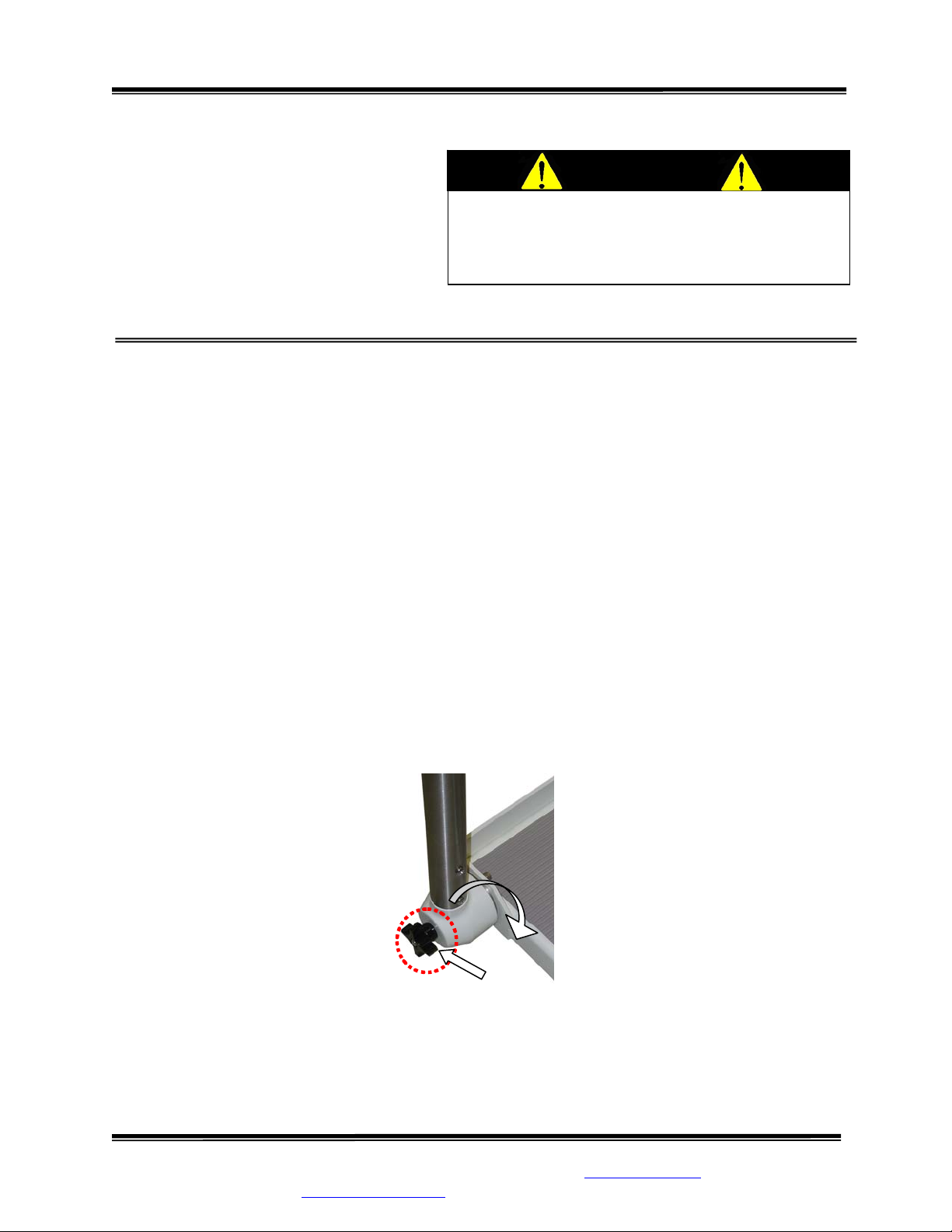
STEP 10: (Figure 5) Open Ramp (7) by releasing the Ramp
Locking Pin (8) located on the right side of the Ramp near
7
Transport Wheel (9).
8
9
Figure 5: Ramp Locking Pin
REPLACEMENT PARTS and ACCESSORIES
Part # Description
CA3066 Display Label
FKDK57
Mast Wing Nut
MF1956 Leveling Foot Spacer
FK2284T52 Leveling Foot
SInstruments, Inc.
Tel: 716-693-5977 Fax: 716-693-5854 URL: www.srscales.com
email: sri@srinstruments.com
, 600 Young Street, Tonawanda, NY 14150
Copyright 2010 SInstruments, Inc.

Model SR725 Series Wheelchair Scale System
Operating and Service Manual - S/N 4068+
Part No. MAN725_100928 Page 6 of 16
SYSTEM DESCRIPTION and INTENDED USE
SYSTEM DESCRIPTION
The SR725 Wheelchair Scale System employs the latest in microprocessor and load cell technology to
provide accurate and repeatable weight data. Four (4) identically matched transducers are strategically
placed to ensure an accurate representation of the patient’s weight.
The low power microprocessor circuitry allows the SR725 Wheelchair Scale System to derive its power
from six (6) common “D” cell batteries that will provide up to 10,000 weight readings before needing
replacement. This eliminates the need for an external battery charger or the danger of an AC power
supply cord on a portable scale.
The patient’s weight is displayed on a 16-character dot matrix LCD. With a push of a button, weight
data may be viewed, in either pounds or kilograms, with a displayed resolution of 0.1 for each.
INTENDED USE
The SR725 Wheelchair Scale System is designed for
use as a weighing system for non-ambulatory wheelchair bound patients. Maximum weight capacity must
not exceed 1000 pounds or 454 kilograms, combined
patient/wheelchair gross weight.
WARNING
DO NOT EXCEED
MAXIMUM WEIGHT LIMIT OF
1000 LB / 454 KG
SInstruments, Inc.
Tel: 716-693-5977 Fax: 716-693-5854 URL: www.srscales.com
email: sri@srinstruments.com
, 600 Young Street, Tonawanda, NY 14150
Copyright 2010 SInstruments, Inc.
Model SR725 Series Wheelchair Scale System
Operating and Service Manual - S/N 4068+
Part No. MAN725_100928 Page 7 of 16
MAINTENANCE and CLEANING
The Display Unit for the SR725 Wheelchair
Scale System is made of a powder-coated
aluminum. Exercise caution when cleaning
the display window as it is made of clear
polyester and can be scratched by abrasive
cleaners. Mild soap and water is
DO NOT use pressurized water or steam. The
scale system contains microprocessor circuitry
and strain gauge sensors that may be adversely
affected by exposure to such an environment.
WARNING
recommended for general cleaning and
disinfecting.
STORAGE and TRANSPORTATION
STORAGE
If storing this equipment for periods longer than three (3) months, remove the batteries. To maintain
proper operation of this instrumentation, storage and transport conditions should not vary outside the
following conditions: Relative Humidity 0% to 85%, Ambient Temperature 14°F to 122°F (-10°C to
+50°C).
TRANSPORTATION
To transport the scale, fold Ramp (see Figure 4) in to the closed position and lo ck with the Ra mp Locking
Pin. Loosen the Mast Wing Nut (Figure 5). Lift the Mast Pipe Assembly away from the scale to free it
from the internal locking pin, and swing into position, para llel with th e platf orm . Ensure that th e internal
locking pin engages into the lock position. Tighten the Mast Wing Nut to secure the Mast Pipe
Assembly in position. Hold the Mast Pipe Assem bly close to the Mast Wing Nut and roll the scale to th e
new location.
See ASSEMBLY for detailed instructions to re-assemble the scale system. When placing the
scale system in the new location, care should be taken not to shock the unit. Lift the scale up and
onto the Transport Wheels.
Figure 6: Mast Wing Nut
SInstruments, Inc.
Tel: 716-693-5977 Fax: 716-693-5854 URL: www.srscales.com
email: sri@srinstruments.com
, 600 Young Street, Tonawanda, NY 14150
Copyright 2010 SInstruments, Inc.

Model SR725 Series Wheelchair Scale System
Operating and Service Manual - S/N 4068+
Part No. MAN725_100928 Page 8 of 16
SPECIFICATIONS
MAXIMUM WEIGHT CAPACITY
PLATFORM SIZE
DISPLAY TYPE
DISPLAY RESOLUTION
ACCURACY
AUTO ZERO
AUTO POWER DOWN
HOLD
LAST WEIGHT RECALL
AVERAGING
POWER SUPPLY
1000 lb or 454 kg
SR725: 32 in x 32 in (81 cm x 81 cm)
SR725L: 32 in x 36 in (81 cm x 91 cm)
16-Character dot matrix LCD
0.1 lb/0.1 kg
0.1% +/- 1 digit of displayed resolution for calibrated range
One button operation
Approximately 35 seconds
Stores displayed reading in memory
Press “HOLD” button to recall last stored displayed weight
Automatic digital filter
Six (6) “D” cell batteries
CALIBRATION
OPERATING CONDITIONS
TRANSPORT and STORAGE
Calibration is traceable to NIST standards
Normal operating conditions for this product:
Ambient Temperature Range: 68°F to 85°F (20°C to 30°C)
Relative Humidity Range: 0% to 85%
A void exposure to high-pressure water or steam .
Storage and transport conditions should not vary outside the
following conditions: Relative Humidity 0% to 85%,
Ambient Temperature 14°F to 122°F (-10°C to +50°C).
Remove batteries if storing longer than three (3) months.
SInstruments, Inc.
Tel: 716-693-5977 Fax: 716-693-5854 URL: www.srscales.com
email: sri@srinstruments.com
, 600 Young Street, Tonawanda, NY 14150
Copyright 2010 SInstruments, Inc.

Model SR725 Series Wheelchair Scale System
Operating and Service Manual - S/N 4068+
Part No. MAN725_100928 Page 9 of 16
BUTTON FUNCTIONS
ZERO
The “ZERO” button is used to zero the system before placing a patient onto the scale system.
When pressed, the display message will indicate “ZEROING” “PLEASE WAIT” “HANDS
OFF” “PLEASE WAIT”. Ensure that nothing is in contact with the weighing surface during
this procedure. The display will read “WEIGHT 0.0 LB” (or KG).
Press box under each icon to activate command
Figure 7: Button Display
WEIGH
The “WEIGH” button wakes up the display and shows the patient’s weight if it should Auto
Power Down before the weighing process is done.
HOLD
The “HOLD” button freezes the displayed weight and stores it away in memory. Press
“HOLD” to store the weight into memory. To recall last weight reading, press “HOLD”.
LB/KG MODE
Weight data may be viewed in either pounds or kilograms. Pressing the “LB/KG MODE”
button allows the operator to toggle between the two readings. Both pounds and kilograms are
displayed in a resolution of 0.1.
BASIC SYSTEM OPERATION
SETTING SYSTEM ZERO / DETERMINING WHEELCHAIR WEIGHT
Make sure the scale system is free and clear of any obstructions and press the “ZERO” button. The
displayed message will indicate “ZEROING” “PLEASE WAIT” “HANDS OFF” “PLEASE
WAIT”. Ensure nothing is in contact with the scale system while zeroing. In a few seconds, the display
will read “WEIGHT 0.0 LB” (or KG).
Continued next page
SInstruments, Inc.
Tel: 716-693-5977 Fax: 716-693-5854 URL: www.srscales.com
email: sri@srinstruments.com
, 600 Young Street, Tonawanda, NY 14150
Copyright 2010 SInstruments, Inc.

Model SR725 Series Wheelchair Scale System
Operating and Service Manual - S/N 4068+
Part No. MAN725_100928 Page 10 of 16
BASIC SYSTEM OPERATION cont’d
STEP 1: Place the empty wheelchair (with any blankets or pillows that the patient may have with
them) on the scale platform. Then press the zero button.
NOTE: The display will shut off after 35 seconds. The zero (TARE) will still be stored in
memory.
STEP 2: Remove the wheelchair from the platform. Place the patient in the wheelchair.
STEP 3: Wheel the patient with wheelchair onto the platform. Lock the patient’s wheelchair brake to
prevent movement. Press the weigh button. The display will show the patient’s weight only.
Do not leave patient unattended on the scale platform.
CONTINUOUS WEIGH MODE
In this default mode, the weighing surface remains active. Press the “HOLD” button once to lock the
displayed reading and store it in memory as the “last weight” for recall later if needed.
CAUTION
AUTO-HOLD MODE
This mode is for patients unable to remain still for the weighing procedure. It locks, stores, and displays
the patient’s weight as soon as the “WEIGH” button is pressed once. Note: No weight will be
displayed until the button is pressed.
To enable this mode before zeroing the system, press and hold the “HOLD” button for approximately
five (5) seconds until the display reads “AUTO-HOLD ENABLED”.
To return to CONTINUOUS WEIGH mode when finished, press and hold the “HOLD” button for
approximately five (5) seconds until the display reads “CONTINUOUS WEIGH”.
BATTERY REPLACEMENT
STEP 1: The display will read “REPLACE BATTERY”.
STEP 2: (Figure 8) Unscrew the panel screw on the Battery Compartment Cover (8) and remove the
battery compartment cover.
STEP 3: Remove and replace ALL six (6) “D” cell batteries. Refer to diagram in the battery
compartment for placement.
STEP 4: Press the “WEIGH” button to confirm display is working.
STEP 5: Secure the battery cover using the panel screw.
STEP 6: Zero the system.
8
Figure 8: Battery Compartment Cover Panel Screw
SInstruments, Inc.
Tel: 716-693-5977 Fax: 716-693-5854 URL: www.srscales.com
email: sri@srinstruments.com
, 600 Young Street, Tonawanda, NY 14150
Copyright 2010 SInstruments, Inc.

Model SR725 Series Wheelchair Scale System
Operating and Service Manual - S/N 4068+
Part No. MAN725_100928 Page 11 of 16
THEORY OF OPERATION
SR Instruments patient weighing systems are digital scales. Strain-gauge force cells convert the force
of an applied weight into an analog signal. This signal is amplified by an operational amplifier and
converted to a digital signal by an analog to digital converter. The digital signal is transferred to a
micro-controller where it is filtered, converted to appropriate units, and displayed on a liquid crystal
display.
Strain-gauge force cells each contain four strain gauges mounted in a full Wheatstone-bridge
configuration. These bridges convert the physical movement of the force cell, due to the applied mass
on the system, into minute changes in electrical resistance. These changes in resistance produce a
voltage difference across the Wheatstone-bridge, which is amplified by the operational amplifier. The
amplifier is configured to current sum the output of each cell, with potentiometers se rvin g to ad jus t the
sensitivity (voltage out per unit of weight applied) of each bridg e. The offset potentiometer produces a
small current, which nulls the output of the amplif ier for an unloaded sy stem .
The output of the operational amplifier is digitized by the analog to digital converter. The converter
integrates the analog signal onto the integrating capacitor over a short interval. The integrating
capacitor is then discharged at a rate proportional to the reference voltage applied to the converter.
The residual voltage on the integrating capacitor is then multiplied by a factor and again discharged at
a rate proportional to the reference voltage. The residual voltage from this discharge is again
multiplied by a factor and again discharged. The time taken to disc harge the capacitor is proportional
to the voltage from the operational amplifier, which is proportional to the applied load on the force
cells. The time is stored as a binary number in the analog to digital converter and is transferred to the
micro-controller when the conversion is complete.
The micro-controller averages and filters the digital output of the analog to digital converter, subtracts
the value saved during the system zero operation and scales the filtered output, then displays the result
on the liquid crystal display. The micro-controller perfor ms a rolling average of data for continuous
weigh and, for AutoHold, the micro-controller averages the data before locking in on the reading. If
the data variance is greater than 0.1% in the AutoHold mode, the micro-controller will reset the filter
and start a new averaging period.
The micro-controller can be placed in a calibration mode, where the system can be re-calibrated. In
the calibration mode, the result of the weigh operation is scaled to match the value by adjusting the
“up” and “down” calibration buttons. This new calibration factor is then stored in the non-volatile
memory.
SInstruments, Inc.
Tel: 716-693-5977 Fax: 716-693-5854 URL: www.srscales.com
email: sri@srinstruments.com
, 600 Young Street, Tonawanda, NY 14150
Copyright 2010 SInstruments, Inc.

Model SR725 Series Wheelchair Scale System
Operating and Service Manual - S/N 4068+
Part No. MAN725_100928 Page 12 of 16
CALIBRATION
IMPORTANT
CALIBRATION CHECK Qualified service personnel only should perform this procedure.
Load cells have no user serviceable components and should not be tampered with for any
reason. Re-calibration is generally not required, but should be verified periodically to ensure
accuracy. The recommendation for calibration check is at least once every 12 months, or as
individual maintenance policy requires.
“-” “+”
Figure 9: Calibration Button Diagram
NOTE: Ensure that nothing is in contact with the scale system during this procedure. Remove hands
from the system when noting the displayed calibration results.
STEP 1: Remove the right-hand end-cap to access the PC Board. The calibration buttons are located
on the right side of the PC Board.
STEP 2: (Figure 9) Press and hold both buttons simultaneously
(SW5 and SW6).
STEP 3: The display will read “HOLD TO CAL” as the right hand
digit counts down to enter the CAL mode.
STEP 4: When in the CAL mode, press the “ZERO” button to zero
the display.
STEP 5: Place a known calibrated weight, traceable to NIST, onto the
weighing surface and compare it to the displayed reading. Note: DO
NOT USE barbell weights or calibrate to a mechanical scale.
STEP 6: Use the “-” or “+” button to make corrections to the
displayed weight. The displayed value should be within 0.1% of the
calibrated weight, plus or minus 1 digit of reading.
CALIBRATION
TOLERANCE TABLE
LOW
LIMIT
99.9 100.0 100.1
199.8 200.0 200.2
299.7 300.0 300.3
399.6 400.0 400.4
499.5 500.0 500.5
599.4 600.0 600.6
699.3 700.0 700.7
799.2 800.0 800.8
899.1 900.0 900.9
999.0 1000.0 1001.0
APPLIED
LOAD
HIGH
LIMIT
STEP 7: When settings are completed:
Press the “HOLD” button to SAVE the
settings or press the “WEIGH” button to
CANCEL. Both choices will EXIT the CAL
mode.
The integrated circuits and semiconductors on
the printed circuit boards may be damaged by
electrostatic discharge (ESD). Be sure to use
proper handling precautions at all times.
CAUTION
SInstruments, Inc.
Tel: 716-693-5977 Fax: 716-693-5854 URL: www.srscales.com
email: sri@srinstruments.com
, 600 Young Street, Tonawanda, NY 14150
Copyright 2010 SInstruments, Inc.

Model SR725 Series Wheelchair Scale System
Operating and Service Manual - S/N 4068+
Part No. MAN725_100928 Page 13 of 16
INITIALIZATION
INITIALIZATION PROCEDURE
To be used ONLY IF REPLACING IC5 or if DISPLAY READS DOUBLE
Internal Initialization Buttons
SW5
Figure 10: Location of Internal Initialization Button
SW2
STEP 1: Remove both end-caps to access the PC Board. The initialization buttons (SW2 and SW5)
are located internally on the PC Board (Figure 10).
STEP 2: Simultaneously press buttons indicated to initialize the system. The display will read,
“HOLD TO INIT”, and count down from 9 to 0. When the initializing is complete, the display will
read, “INITIALIZING” and then return to the WEIGH mode.
STEP 3: Follow the CALIBRATION procedure.
The integrated circuits and semiconductors on
the printed circuit boards may be damaged by
electrostatic discharge (ESD). Be sure to use
proper handling precautions at all times.
CAUTION
SInstruments, Inc.
Tel: 716-693-5977 Fax: 716-693-5854 URL: www.srscales.com
email: sri@srinstruments.com
, 600 Young Street, Tonawanda, NY 14150
Copyright 2010 SInstruments, Inc.

Model SR725 Series Wheelchair Scale System
Operating and Service Manual - S/N 4068+
Part No. MAN725_100928 Page 14 of 16
TROUBLESHOOTING
SYMPTOM REASON/CORRECTIVE ACTION
The characters only appear on half of the
display.
Press the “WEIGH” button or remove one battery.
Wait five seconds, then re-install the battery, and try
the “WEIGH” button again.
The display lights appear to work, but do
not respond to button activation.
Button may not have “bounced” back up after being
pressed. Remove the faceplate and inspect buttons.
Make sure the rubber “boot” is not sitting too high.
Re-attach the plate.
The display shows no reading at all.
Check to ensure batteries are installed correctly (see
directions for BATTERY REPLACEMENT).
Check display cable to make sure it is connected
securely.
For additional information or assistance, telephone our Service Hotline: 1-800-654-6360
or e-mail: sri@srinstruments.com
SInstruments, Inc.
Tel: 716-693-5977 Fax: 716-693-5854 URL: www.srscales.com
email: sri@srinstruments.com
, 600 Young Street, Tonawanda, NY 14150
Copyright 2010 SInstruments, Inc.

Model SR725 Series Wheelchair Scale System
Operating and Service Manual - S/N 4068+
Part No. MAN725_100928 Page 15 of 16
WARRANTY
FOUR YEAR LIMITED WARRANTY
Each S system is manufactured with high quality components. SR Instruments, Inc.
warrants that all new equipment will be free from defects in material or workmanship, under
normal use and service, for a period of four (4) years from the date of purchase by the original
purchaser. Normal wear and tear, injury by natural forces, user neglect, and purposeful
destruction are not covered by this warranty. Warranty service must be performed by the factory
or an authorized repair station. Service provided on equipment returned to the factory or
authorized repair station includes labor to replace defective parts. Goods returned must be shipped
with transportation and/or broker charges prepaid. SR Instruments, Inc.’s obligation is limited to
replacement of parts that have been so returned and are disclosed to SR Instruments, Inc.’s
satisfaction to be defective. The provisions of this warranty clause are in lieu of all other
warranties, expressed or implied, and of all other obligations or liabilities on SR Instruments,
Inc.’s part, and it neither assumes nor authorizes any other person to assume for SR Instruments,
Inc. any other liabilities in connection with the sale of said articles. In no event shall SR
Instruments, Inc. be liable for any subsequent or special damages. Any misuse, improper
installation, or tampering, shall void this warranty.
DAMAGED SHIPMENTS
Title passes to purchaser upon delivery to Transportation Company. Any claims for shortage or
damage should be filed with the delivery carrier by purchaser.
RETURN POLICY
All products being returned to SR Instruments, Inc. require a Return Goods Authorization number
(RGA). To receive an RGA, call our Technical Service Team at 716-693-5977 or toll-free in the
USA and Canada at 800-654-6360.
When inquiry is made, please supply model and serial numbers, purchase order, if the scale was
bought on contract, and reason for return.
Generally, deleted, damaged, and outdated merchandise will not be accepted for credit. A
minimum restocking charge of 15% will be assessed on return of current merchandise.
All returns are to be shipped FREIGHT PREPAID to: SR Instruments, Inc., 600 Young Street,
Tonawanda, NY 14150.
RESTOCKING FEE
• 15% fee for any scale that has been opened and used
• 10% fee for any scale returned that has been ordered incorrectly or refused delivery with
no model change
• 5% fee if an error in ordering has been made and a different model exchanged
• No fees will be charged if the scale is returned because of an error on the part of SR
Instruments, Inc.
• No returns accepted after 60 days.
SInstruments, Inc.
Tel: 716-693-5977 Fax: 716-693-5854 URL: www.srscales.com
email: sri@srinstruments.com
, 600 Young Street, Tonawanda, NY 14150
Copyright 2010 SInstruments, Inc.

Model SR725 Series Wheelchair Scale System
Operating and Service Manual - S/N 4068+
Part No. MAN725_100928 Page 16 of 16
By SInstruments, Inc.
Precision & Technology in
Perfect Balance
®
SInstruments, Inc.
Tel: 716-693-5977 Fax: 716-693-5854 URL: www.srscales.com
email: sri@srinstruments.com
, 600 Young Street, Tonawanda, NY 14150
Copyright 2010 SInstruments, Inc.
 Loading...