

SR Instruments SR725, SR725L Operating And Service Manual
Model SR725 Series Wheelchair Scale System
Operating and Service Manual - S/N 4068+
Part No. MAN725_100928 Page 1 of 16
by S Instruments, Inc.
Model
SR725 / SR725L
Wheelchair Scale System
Operating and Service
Manual
Serial Numbers: 4068+
SInstruments, Inc.
Tel: 716-693-5977 Fax: 716-693-5854 URL: www.srscales.com
email: sri@srinstruments.com
, 600 Young Street, Tonawanda, NY 14150
Copyright 2010 SInstruments, Inc.

Model SR725 Series Wheelchair Scale System
Operating and Service Manual - S/N 4068+
Part No. MAN725_100928 Page 2 of 16
TABLE OF CONTENTS
TABLE OF FIGURES ......................................................................................................................2
PACKING CHECKLIST SR725 .....................................................................................................3
PACKING CHECKLIST SR725L ..................................................................................................3
ASSEMBLY.......................................................................................................................................4
REPLACEMENT PARTS AND ACCESSORIES ........................................................................5
SYSTEM DESCRIPTION AND INTENDED USE .......................................................................6
MAINTENANCE AND CLEANING ..............................................................................................7
STORAGE AND TRANSPORTATION ........................................................................................7
SPECIFICATIONS...........................................................................................................................8
BUTTON FUNCTIONS ...................................................................................................................9
BASIC SYSTEM OPERATION ......................................................................................................9
BATTERY REPLACEMENT .......................................................................................................10
THEORY OF OPERATION .........................................................................................................11
CALIBRATION ..............................................................................................................................12
INITIALIZATION .........................................................................................................................13
TROUBLESHOOTING .................................................................................................................14
WARRANTY...................................................................................................................................15
TABLE OF FIGURES
Figure 1: Assembly Diagram ....................................................................................................... 4
Figure 2: Display Unit Cable Connection ................................................................................... 4
Figure 3: Display Unit .................................................................................................................... 5
Figure 4: Battery Cover Display Unit ......................................................................................... 5
Figure 5: Ramp Locking Pin ........................................................................................................ 5
Figure 6: Mast Wing Nut ............................................................................................................. 7
Figure 7: Button Display .............................................................................................................. 9
Figure 8: Battery Compartment Cover Panel Screw .............................................................. 10
Figure 9: Calibration Button Diagram ..................................................................................... 12
Figure 10: Location of Internal Initialization Button ................................................................ 13
SInstruments, Inc.
Tel: 716-693-5977 Fax: 716-693-5854 URL: www.srscales.com
email: sri@srinstruments.com
, 600 Young Street, Tonawanda, NY 14150
Copyright 2010 SInstruments, Inc.
Model SR725 Series Wheelchair Scale System
Y
Y
Operating and Service Manual - S/N 4068+
Part No. MAN725_100928 Page 3 of 16
PACKING CHECKLIST SR725
Wheelchair Scale System
DESCRIPTION QUANTIT
√
BASE ASSEMBLY: 32 in x 32 in (81 cm x 81 cm)
WITH ATTACHED MAST PIPE AND RAMP
DISPLAY UNIT 1 ea
PACKAGE OF SIX (6) “D” CELL BATTERIES 1 ea
CALIBRATION CERTIFICATE 1 ea
WARRANTY CARD 1 ea
MANUAL 1 ea
1 ea
PACKING CHECKLIST SR725L
Wheelchair Scale System
DESCRIPTION QUANTIT
√
BASE ASSEMBLY: 32 in x 36 in (81 cm x 91 cm)
WITH ATTACHED MAST PIPE AND RAMP
DISPLAY UNIT 1 ea
PACKAGE OF SIX (6) “D” CELL BATTERIES 1 ea
CALIBRATION CERTIFICATE 1 ea
WARRANTY CARD 1 ea
MANUAL 1 ea
1 ea
SInstruments, Inc.
Tel: 716-693-5977 Fax: 716-693-5854 URL: www.srscales.com
email: sri@srinstruments.com
, 600 Young Street, Tonawanda, NY 14150
Copyright 2010 SInstruments, Inc.
Model SR725 Series Wheelchair Scale System
Operating and Service Manual - S/N 4068+
Part No. MAN725_100928 Page 4 of 16
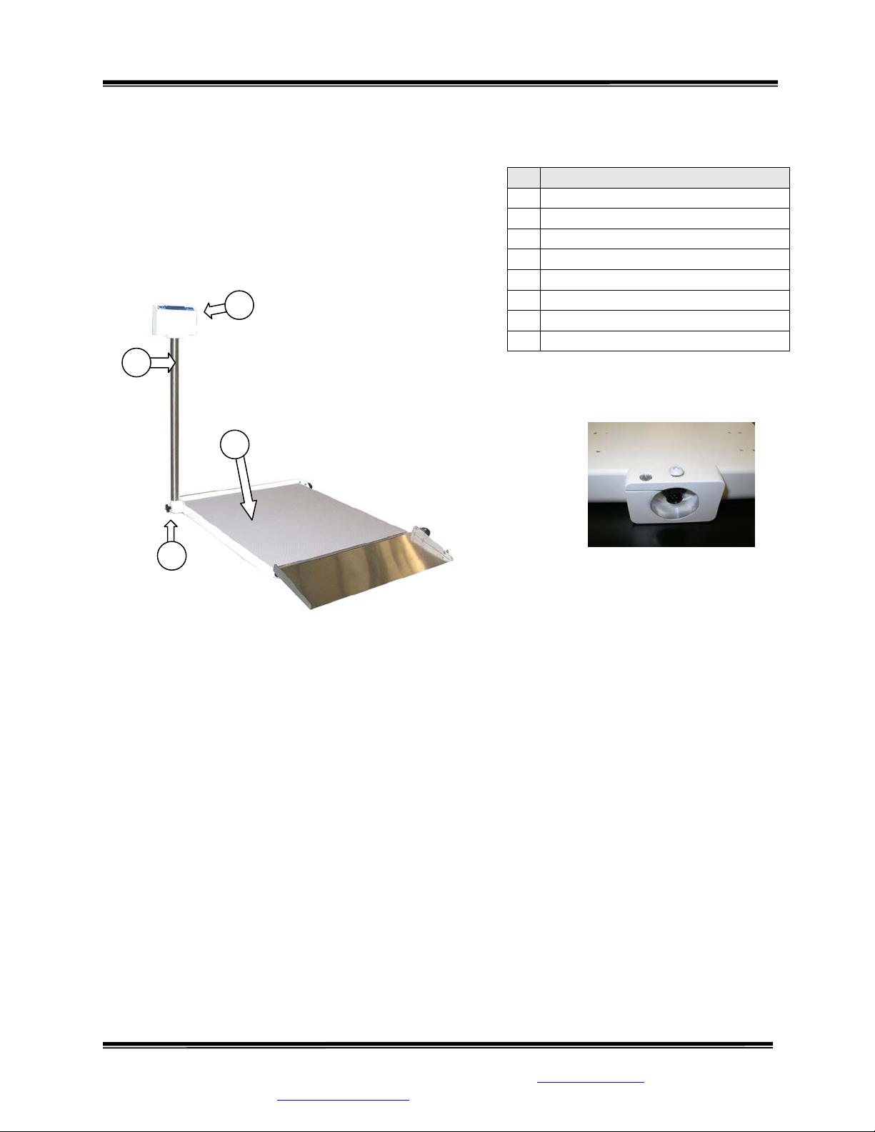
ASSEMBLY
STEP 1: Unpack the scale system and check parts against
the PACKING CHECKLIST. If there are any missing or
damaged parts, please call the Service Hotline at: 1-800654-6360.
STEP 2: Verify that the serial number on the Display
Unit (1) matches that on the Base A ssembly (3 ).
1
2
Figure 1: Assembly Diagram
# PART NAME
Display Unit
1
Mast Pipe
2
Base Assembly
3
Mast Wing Nut
4
Battery Compartment Cover
5
Ramp
6
Ramp Locking Pin
7
Transport Wheels
8
3
4
Figure 2: Display Unit
Cable Connection
STEP 3: (Figure 1) Lay the Base Assembly (3) with the attached Mast Pipe (2) on the floor.
STEP 4: Loosen the Mast Wing Nut (4) to unlock the Mast Pipe. Pull the Mast Pipe out and away
from the scale to free it from the internal locking pin and swing it up until the Mast Pipe is
perpendicular to the platform. Gently push the Mast Pipe against the Base Assembly, engaging it
in the lock position.
STEP 5: Tighten the Mast Wing Nut to secure the Mast Pipe in place.
STEP 6: (Figure 2) Connect the display cable (pre-installed in Mast Pipe) into its mate located
in the base of the Display Unit. Secure the connection by giving the attached lock ring a 1/4 turn
to the right.
Continued next page
SInstruments, Inc.
Tel: 716-693-5977 Fax: 716-693-5854 URL: www.srscales.com
email: sri@srinstruments.com
, 600 Young Street, Tonawanda, NY 14150
Copyright 2010 SInstruments, Inc.
Model SR725 Series Wheelchair Scale System
Operating and Service Manual - S/N 4068+
Part No. MAN725_100928 Page 5 of 16
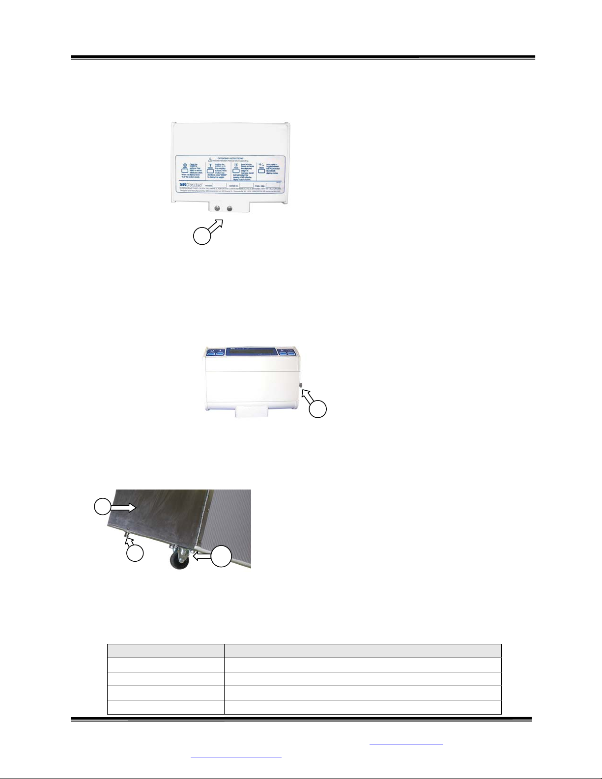
ASSEMBLY Cont’d
Figure 3: Display Unit
5
STEP 7: (Figure 3) Insert the mast pipe into the display post mount assem bly. Tighten the 10-32 x 3/8”
Phillips screw(s) and ¼” x 20 x 3/8” Phillips screw (5).
STEP 8: Unscrew and remove the Battery Compartment Cover (6). Install the six (6) “D” cell batteries
as indicated on the plastic battery cradle. Replace the cover (Figure 4).
Figure 4: Battery Cover Display Unit
6
STEP 9: Adjust leveling feet, located in each of the four corners of the underside of the Base
Assembly, to ensure that the scale will sit level on the floor. Note: Leveling feet m ust be in plac e to
operate the scale properly.
STEP 10: (Figure 5) Open Ramp (7) by releasing the Ramp
Locking Pin (8) located on the right side of the Ramp near
7
Transport Wheel (9).
8
9
Figure 5: Ramp Locking Pin
REPLACEMENT PARTS and ACCESSORIES
Part # Description
CA3066 Display Label
FKDK57
Mast Wing Nut
MF1956 Leveling Foot Spacer
FK2284T52 Leveling Foot
SInstruments, Inc.
Tel: 716-693-5977 Fax: 716-693-5854 URL: www.srscales.com
email: sri@srinstruments.com
, 600 Young Street, Tonawanda, NY 14150
Copyright 2010 SInstruments, Inc.
 Loading...