

Page 1

PMX User Guide Rev. B
May 15, 2008
Portable Mesh Exchange
User’s Guide
SRI International 1
Page 2

PMX User Guide Rev. B
May 15, 2008
Table of Contents
INTRODUCTION........................................................................................................................................ 3
PMX OVERVIEW ........................................................................................................................................ 3
FCC COMPLIANCE AND SAFETY ................................................................................................................. 3
GETTING STARTED ..................................................................................................................................... 4
PMX INVENTORY, INSPECTION AND ASSEMBLY ........................................................................................ 4
INSTALLATION AND SET-UP................................................................................................................. 6
INSTALLATION............................................................................................................................................ 6
PMX ACCESS VIA WEB INTERFACE............................................................................................................ 7
SRI International 2
Page 3

PMX User Guide Rev. B
May 15, 2008
Introduction
PMX Overview
The Portable Mesh Exchange (PMX), is an embedded device that provides enhanced
connectivity for public safety, transportation and other markets. In one unit, SRI delivers
the capability to form a 4.9, 5 or 2.4 GHz mesh network with a backhaul data link or
connection to a Wi-Fi access points via a second radio link.
As a separate node and access point to a mesh, the PMX provides the user with the ability
to expand mesh coverage with the versatility to access the existing networks or attached
cameras. The PMX has two primary configurations; Gateway or Camera. In Gateway
mode, the PMX serves as an interface between wireless mesh networks and existing IP
network via an Ethernet connection. This provides remote drive-up access via wireless
mesh to network attached devices such as cameras, etc. In Camera mode, the PMX can
support one dedicated camera for wireless transmission on the mesh.
The PMX can be installed internally or externally to buildings, poles or structures using
standard mounting hardware. Power is provided over Ethernet or direct DC power if
necessary.
FCC compliance and Safety
The PMX utilizes components which meet FCC regulations and as a unit has been tested
and found FCC compliant.
FCC Compliance Statement
This equipment has been tested and found to comply with the limits for a Class A digital
device, pursuant to Part 15 of the FCC Rules. These limits are designed to provide
reasonable protection against harmful interference when the equipment is operated in a
commercial environment. This equipment generates, uses, and can radiate radio
frequency energy and, if not installed and used in accordance with the instruction manual,
may cause harmful interference to radio communications. Operation of this equipment in
a residential area is likely to cause harmful interference in which case the user will be
required to correct the interference at own expense.
Changes or modifications not expressly approved by the party responsible for compliance
could void the user’s authority to operate the equipment.
SRI International 3
Page 4

PMX User Guide Rev. B
May 15, 2008
FCC PMX Label Statement
The following FCC compliance statement will be visible on the front of a PMX:
This device complies with Part 15 of the FCC Rules. Operation is subject to the following
two conditions: (1) This device may not cause harmful interference, and (2) This device
must accept any interference received, including interference that may cause undesired
operation.
Installation Safety Requirements
Installation of the PMX by certified personnel is recommended in order to comply with
local safety regulations. In addition, the antenna(s) used for this transmitter must be with
a separation distance of at least 45 cm (18 inches) from all persons during normal
operation.
Getting Started
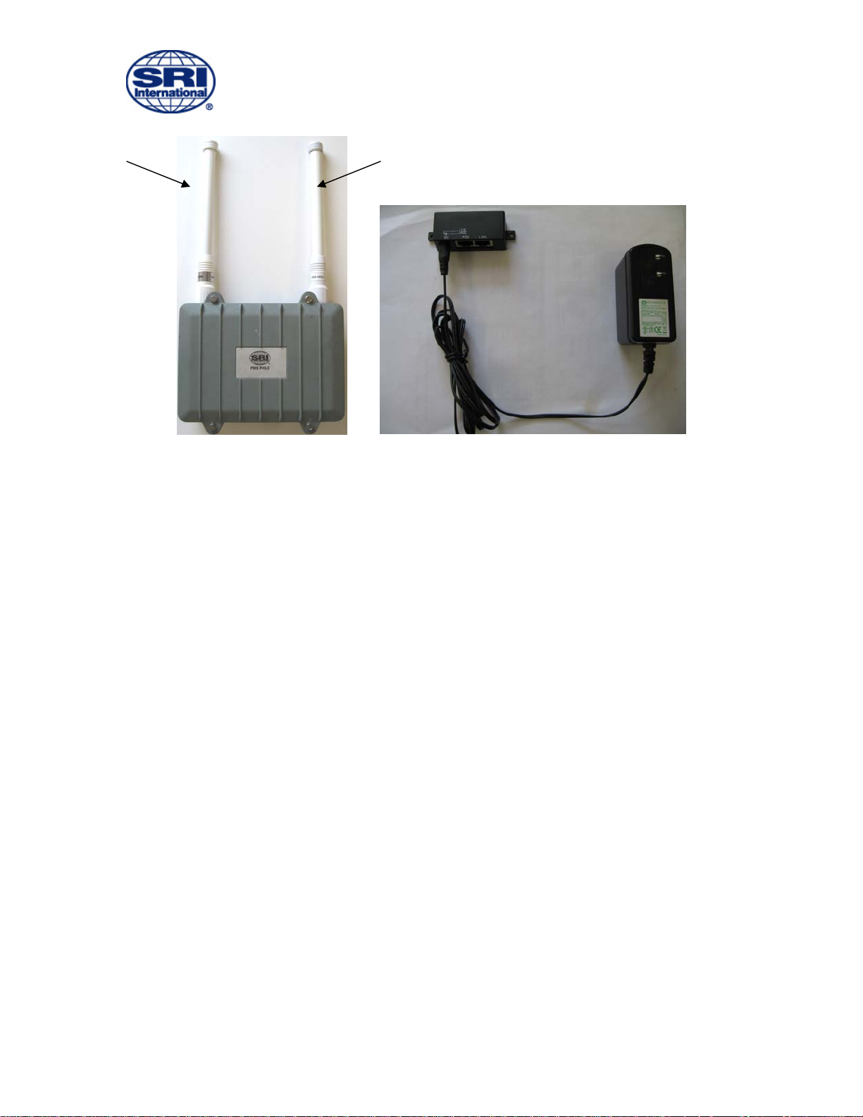
Each PMX unit is packed individually for shipment. The following assembly instructions
are provided for mounting the antennas.
PMX Inventory, Inspection and Assembly
1) Inventory PMX shipping box and inspect for any damage
a. PMX unit
b. POE block and AC/DC power supply (if provided)
c. Installation bracket and mounting hardware
d. 4.9GHz and 5 GHz antenna
2) Install 5 GHz antenna (left side facing front of PMX )
3) Install 4.9 GHz antenna (right side facing front of PMX)
4) Verify antennas tight, be careful not to cross-thread
5) Visually inspect PMX case is tight
6) Screw threads of cover should be flush to 2 threads visible
7) If required for installation, install mounting brackets
SRI International 4
Page 5
PMX User Guide Rev. B
May 15, 2008
Figure #1: PMX Figure #2: POE with AC/DC Power supply
Support Items for Installation
Prior to PMX installation gather the required CAT 5 cabling required and any mounting
equipment necessary for installation.
SRI International 5
Page 6
PMX User Guide Rev. B
May 15, 2008
Installation and Set-Up
Installation
Installation of the PMX is to be performed by the customer using personnel properly
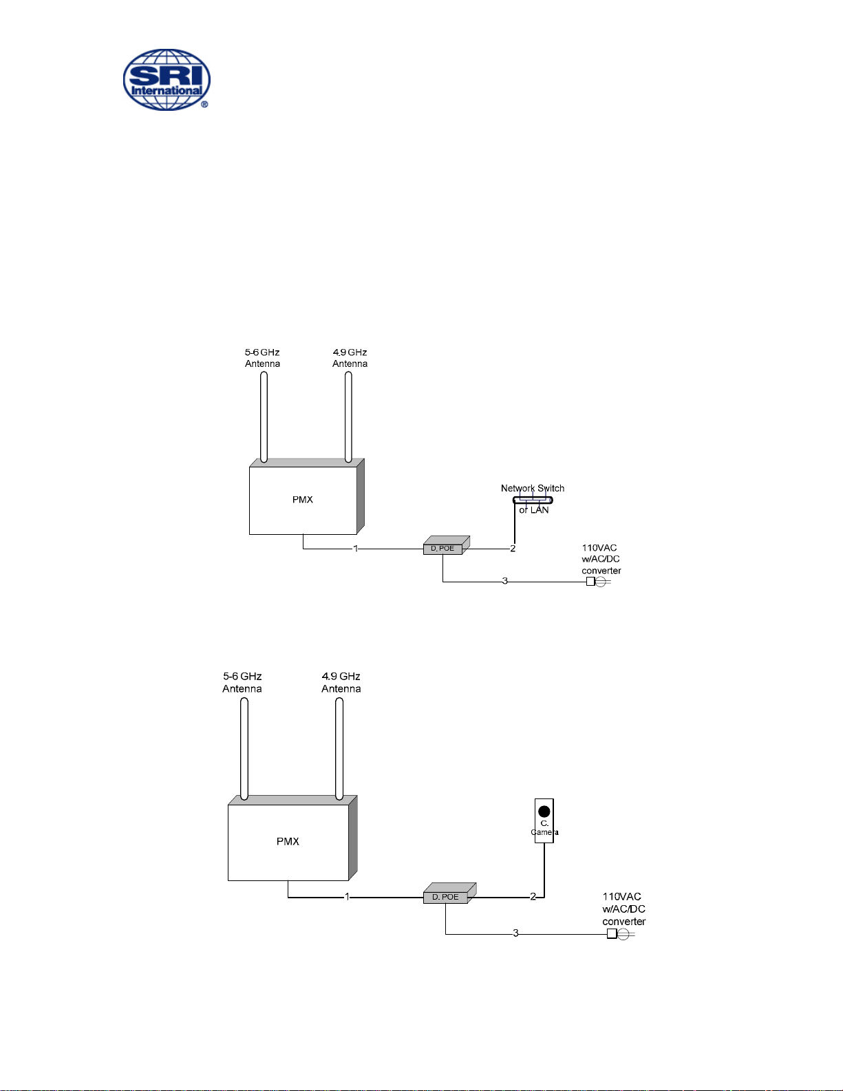
certified for installation of equipment. Once installed in desired location, power is
provided via Ethernet connection. Installation configuration for both Camera and
Gateway mode is provided in the following diagram.
Figure #3: PMX Installation Configuration Gateway Mode
Figure #4: PMX Installation Configuration Camera Mode
SRI International 6
Page 7
PMX User Guide Rev. B
May 15, 2008
PMX Access via Web Interface
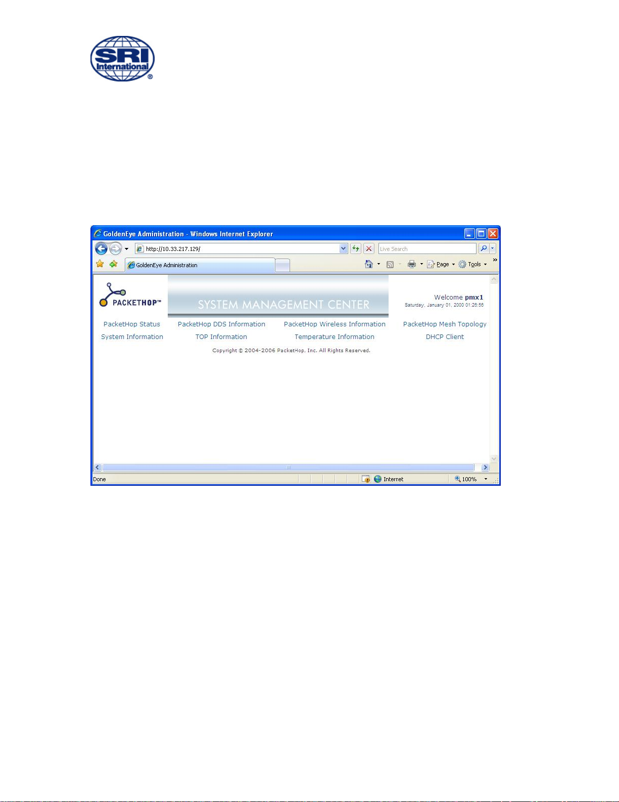
The PMX can be accessed through a web interface using a web browser. Using a test
laptop configured with Mobile Mesh software, the IP address of the unit can be
determined and the unit can be accessed.
Figure #5: PMX Web Interface
Once logged into the PMX, details of unit operation and status are available for
diagnostics and obtaining operational status of the unit.
SRI International 7
 Loading...