

Page 1
Model 302
Six Channel USB PeakSimple Data System
The Model 302 may be used with any brand or model of GC or HPLC offering an analog detector
output signal ranging from -5V to +5V. It includes three independent, programmable controls (0V to +5V
analog output) for temperature & pressure or HPLC gradient formation. The Model 302 has six channels,
which can be randomly assigned to one of four time bases, which allows independent start and stop times for
four separate instruments. Four remote start inputs compatible with 2-wire switch closures (typically output by
GCs and HPLCs as a remote start signal) are also included for your use. T wo pulse stretchers are provided to
accommodate intstruments with remote start signals shorter than one second (such as Hewlett Packard GCs).
The computer to which you connect the Model 302 must support USB (it must have at least one USB
TM
port—rev 2.0 or higher—and use Windows
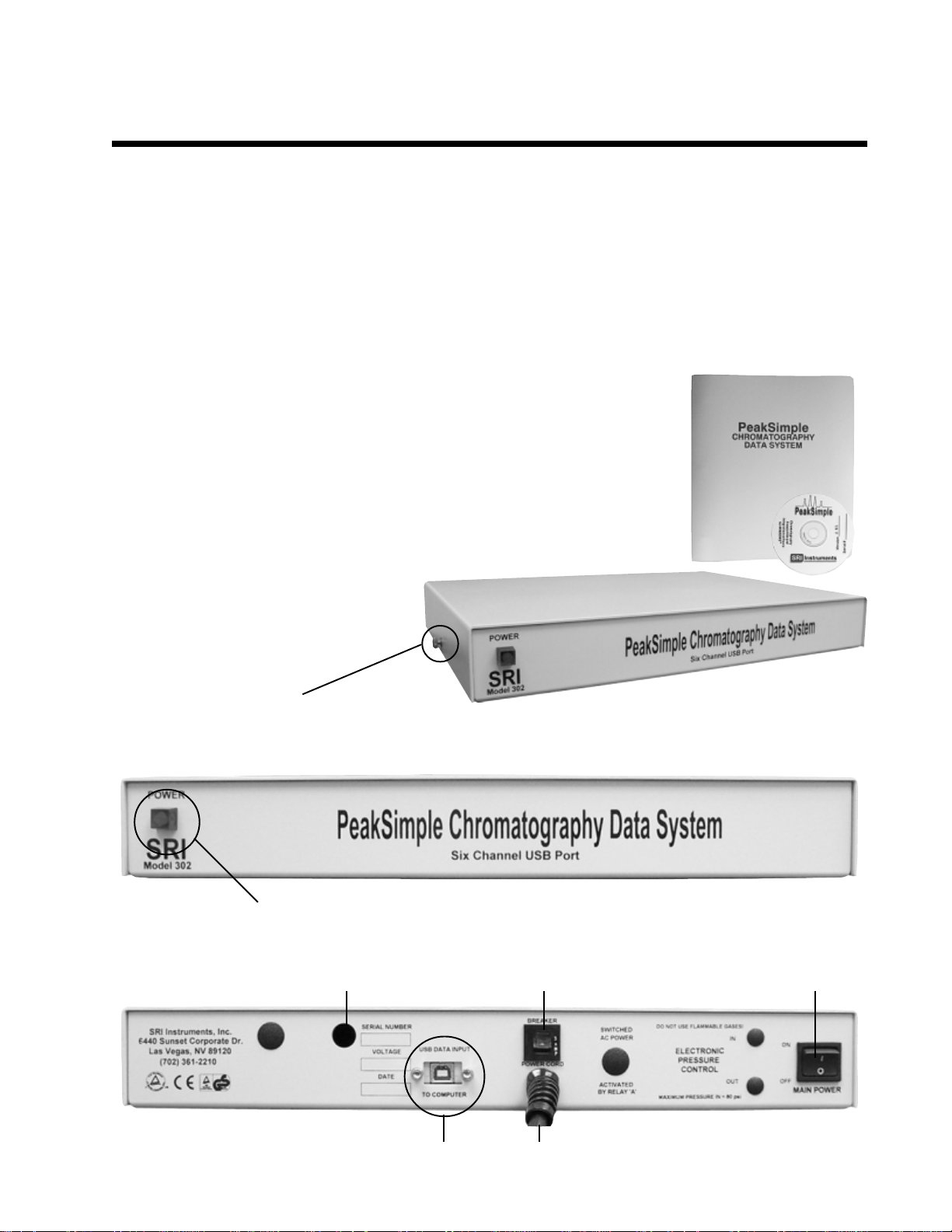
With your purchase of the Model 302, you should receive the following items:
1 - Model 302 Data System box (front and rear views shown below)
2 - USB cable for connection to your computer’s USB port
3 - Manual (either the PeakSimple Chromatography Data Systems or
the SRI general product manual)
4 - PeakSimple for Windows
TM
98, 98SE, ME, 2000, XP or newer).
software (inside the manual cover)
The Model 302 comes in a sturdy
aluminum box consisting of top and bottom
halves, secured together with two brass
thumbscrews for easy interior access.
The brass thumbscrews are on the left- and
right-hand panels of the Model 302 box.
POWER Indicator LED
Opening for analog signal cable(s)
and remote start device connections POWER switch
Front View
Rear View
Breaker
USB connector Power cord
Page 2
Model 302
Six Channel USB PeakSimple Data System
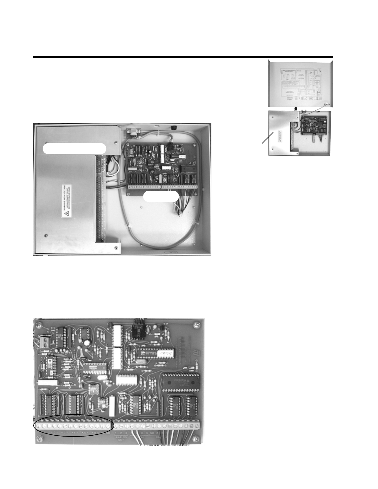
1. Open the Model 302
V erify that the Model 302 is powered OFF and unplugged. Remove the thumbscrews
on both sides of the Model 302 box and slide the top cover up and off. It is
connected to the bottom of the box by a ground wire, so just set it next to the
bottom half of the box.
High voltage
aluminum
Power Supply board
A/D board
safety cover
The Model 302 box contains two circuit
boards. The board on the right-hand side
is the A/D board. The board on the lefthand side under the removable high voltage
aluminum safety cover is the Power Supply
board. If you need to remove the high
voltage aluminum safety cover,
ALWAYS unplug the Model 302 fr om
the wall power outlet first (you do not
need to remove it for the wiring
connections described here).
2. Connect the Analog Signal Cable(s)
NOTE: The analog output from some GCs and LCs can have a range of up to 10 volts DC. The Model 302
can tolerate this voltage input, but signals above 6 volts will generate unwanted noise and signals above 5 volts
will be “clipped” (the tops of the waveforms will be cut off). Use the 1 volt output typically available on the
back of your instrument.
2-1. Route the analog signal cables from your instrument through the open hole in the back of the Model 302.
2-2. Strip 1/4” of insulation from the
“signal+” and “signal-” wires of your
instrument’ s signal cables.
2-3. Remove any jumpers placed in the
Channels 1-6 screw terminals at the factory .
Insert the “signal+” wire into the A/D board
screw terminal marked “1 +” and secure the
connection with a small flat-blade
screwdriver.
2-4. Insert the “signal-” wire into the A/D
board screw terminal marked “1 -” and
secure the connection.
2-5. Repeat the connection of signal cables
for channels 2, 3, 4, 5, and 6. Any unused
channels MUST have both inputs jumpered
Channels 1-6 and GD (ground) screw terminals
to ground.
Page 3
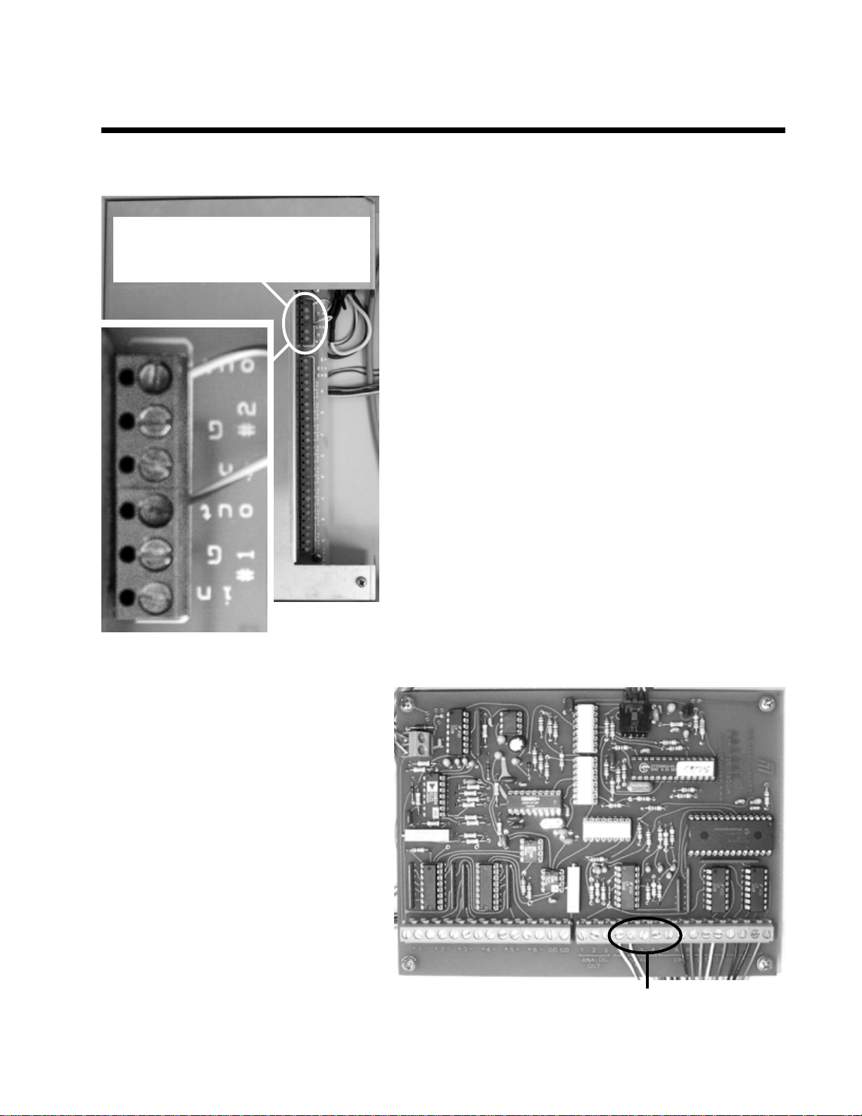
The remote start wires for the first two
instruments are inserted into these screw
terminals on the Power Supply board.
Model 302
Six Channel USB PeakSimple Data System
3. Connect the Remote Start Cables (OPTIONAL)
The Model 302 remote start capability allows you to start the
data system by means of a switch closure. Four separate remote
start circuits permit the user to individually start TIMEBASE 1,
2, 3, and 4 of the data system. In some applications, the
chromatograph being used with the Model 302 may offer a
remote start signal output or switch closure output that permits
starting an integrator or other device when the ST AR T button
is pressed on the chromatograph’s on-board control panel.
Typically, this signal can be used to start the Model 302.
TIMBASES 1 and 2 are equipped with pulse stretchers.
3-1. Route the remote start cable from your instrument through
the open hole in the back of the Model 302.
3-2. Strip 1/4” of insulation from the “+” and “-” wires of your
remote start cable(s).
3-3. Insert the “+” wire into the Power Supply board screw
terminal marked “#1 IN” and secure the connection.
3-4. Insert the “-” wire into the Power Supply board screw
terminal marked “#1 G” and secure the connection.
3-5. For a second instrument, insert the “+” wire into the “#2
IN” terminal, and the “-” wire into the “#2 G” terminal.
3-6. The screw terminals for the third and
fourth instruments’ remote starts are on the
A/D board. The bank of screw terminals is
labeled “DIGITAL IN” under “1 2 3 4.”
Connect the “+” wires for the third and fourth
instruments to screw terminals 3 and 4,
respectively . Connect both “-” wires to the
“GD” screw terminal next to the “4” screw
terminal (on the right-hand side).
NOTE: TIMBASES 3 and 4 require a
remote start signal that persists longer for than
one second. Check your instruments’
specifications (for example, Hewlett Packard
GCs produce a very short remote start pulse,
so you should connect one of these to
TIMEBASE 1 or 2, which are equipped with
pulse stretchers).
1234GD
Connect the remote start “+” cables to screw terminals “3” & “4,”
and the “-” cables to “GD”.
Page 4
Model 302
Six Channel USB PeakSimple Data System
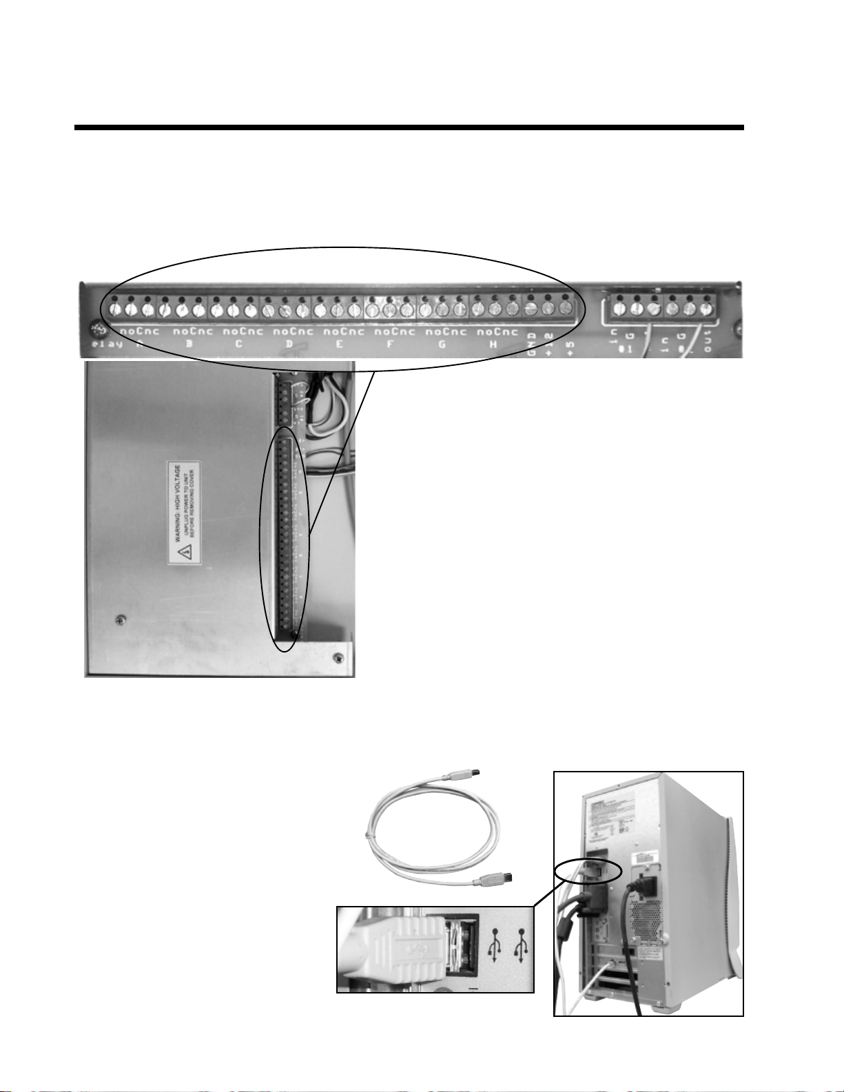
4. Connect the External Event Relay Wires (OPTIONAL)
The Model 302 has eight 0-5 volt TTL level outputs that are wired to a bank of mechanical relays with screw
terminals for easy connection to any device which may be operated from a contact closure (normally open
[NO] and normally closed [NC] contact closures). These relays may be turned ON and OFF individually and
automatically through a PeakSimple timed event table. Manual control is also available via the computer
keyboard.
Connect your devices to the A-H Relay screw terminals
4-1. Route the external event wires from your instrument
through the open hole in the back of the model 302.
4-2. Strip 1/4” of insulation off of each wire.
4-3. Select which device should be connected to each
event (“A” through “H”), then insert the wire into the
appropriate screw terminal on the Power Supply board,
and secure the connection. Make and keep a list of each
device you connect and the Relay it is connected to for
your reference (you will need this information to activate
the devices automatically with an event table or manually
with the mouse).
5. Replace the cover on the Model 302 and secure it with the thumbscrews.
6. Connect the USB Cable to Your Computer
The Model 302 is equipped with a
USB connector. A USB cable
(provided) connects the Model 302
to your WindowsTM computer’s USB
port. This plug and play interface
permits the Model 302 to be loaded
onto and operated from a desktop or
laptop computer that supports USB
(rev . 2.0 or higher).
6-1. Secure one end of the USB cable
to an available USB port on your PC.
6-2. Secure the other end to the USB
connector on the back of the Model
302.
USB cable
USB port
Page 5
Six Channel USB PeakSimple Data System
7. Connect Power to the Model 302
The Model 302 is provided with a power cord which
plugs into a standard 110 (or 220) volt outlet. Plug the
Model 302 into the wall outlet. Turn ON the power switch
and verify that the POWER LED on the front of the Model
302 is lit.
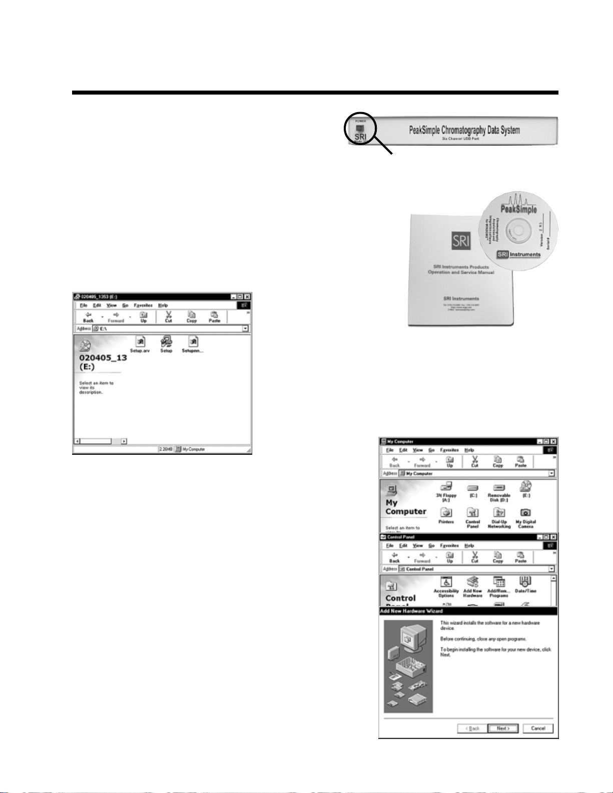
8. Install PeakSimple Chromatography Software
8-1. Locate your copy of PeakSimple, which is shipped inside the front
cover of your manual. Insert the CD or floppy disk(s) into your computer’s
appropriate drive.
8-2. Open the appropriate drive through My Computer, then double
click on “Setup.exe” and follow the instructions. By default, the
setup program places the PeakSimple application directory on the
hard drive: c:\peak2000. If you put the application directory
elsewhere, take note of the path as you may have to enter it in a
dialog box during the USB driver installation procedure.
The power LED is lit when the Model 302 is
connected to a power source & switched ON.
Model 302
9. Install the USB Drivers
There are three important files saved to the PeakSimple application
directory at the conclusion of the software installation: LL_USB.inf,
LL_USB.sys, and LL_USB2K.sys. These files are required for
Windows to recognize the A/D board connected to the computer’ s
USB port.
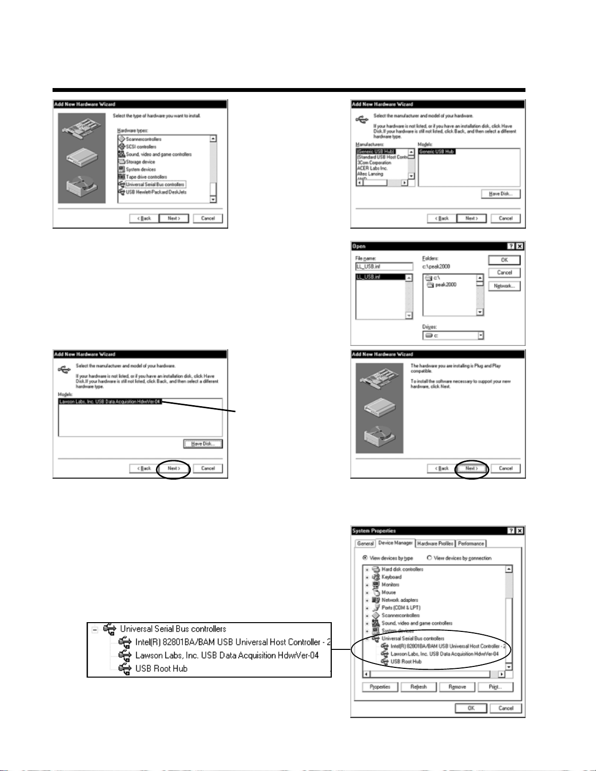
9-1. Double-click on the My Computer icon on your desktop, then
on Control Panel, then on Add New Hardware, which should open
the Add New Hardware Wizard.
9-2. Click the Next button twice, until you get to the screen that
gives you a choice between letting Windows find the new hardware,
or selecting it yourself from a list. Click the radio button to choose
the hardware from a list and click the Next button.
Page 6
Model 302
Six Channel USB PeakSimple Data System
9-3. Scroll down the
hardware list, click on
Universal Serial Bus
controllers, then click
Next. From the
following screen click
the Have Disk button.
9-4. Click Browse and navigate to the PeakSimple application
directory , or type in the path (“c:\peak2000” or the name you
have chosen). The Wizard should find the LL_USB.inf file. When
you click OK, the Wizard will verify that you want to copy files
from the PeakSimple directory (“Copy manufacturer’s files from:
c:\peak2000”).
9-5. When you click
OK again, the Wizard
will confirm that the
drivers are for Lawson
Labs. Click Next on
this screen and the
following screen, and
Windows will finish
installing the software
for the Model 302.
Click Finish.
9-6. Restart your computer (you MUST restart your computer
before the drivers will work). Open the Control Panel again, then
System, then click on the Device Manager tab. If the USB drivers
have been successfully installed, the Universal Serial Bus controllers
section will list “Lawson Labs, Inc. USB Data Acquisition
HdwrVer-04.”
Page 7
Six Channel USB PeakSimple Data System
10. Launch PeakSimple
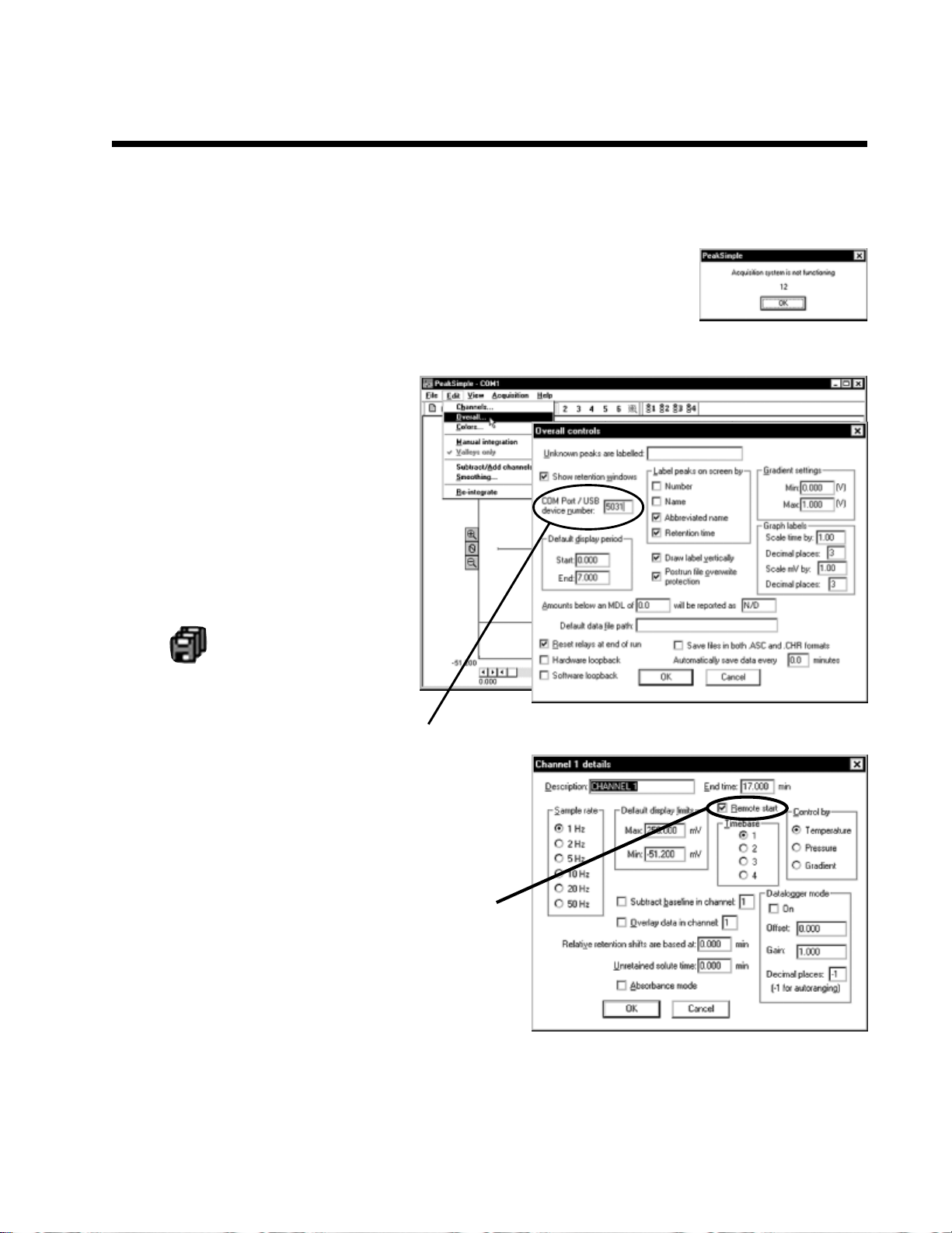
10-1. Double-click on the PeakSimple icon to launch the program. V erify that
communication has been established between your computer and the Model 302.
An error message will appear if communication is not established. This is normal
until you complete the following step.
10-2. Each SRI USB data system has a
unique 4-digit USB device number
beginning with “5” (5031, 5032, etc.).
This I.D. number is printed on the back
of your Model 302, and on your
PeakSimple disk. Open the PeakSimple
Edit menu and choose Overall. Enter
your Model 302 I.D. number in the box
labeled “Com port / USB device number.”
Click OK, and PeakSimple will attempt
to “wake-up” the data system. Click the
Model 302
Save All icon so you don’t have to
re-enter the USB device number.
Enter the 4-digit USB device number here
10-3. For the remote start option:
Open the Edit menu and choose Channels. Click on
the Details button for channel 1. Verify that Remote
start is enabled (the box should be checked). Repeat
this step for channels 2-6 if necessary .
10-4. For information about using Event tables, manual Relay activation, etc., see the “PeakSimple Tutorials”
and the “PeakSimple Software” sections in the manual (and online at www .srigc.com—click on the “Download
Our Documents” button on the homepage).
Page 8
Model 302
Six Channel USB PeakSimple Data System
1 1. Starting an Analysis
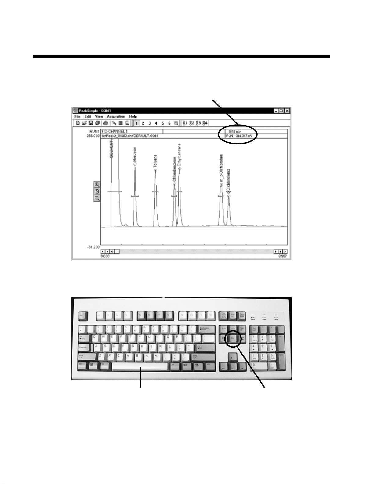
10-1. The upper right corner of the PeakSimple chromatogram window contains real-time information pertinent
to your analysis in progress. The status of the run (ST AND BY , RUN) is displayed in capital letters next to the
millivolt (mV) reading, underneath the amount of time into the run.
11-2. Hit your computer keyboard spacebar to begin the run, and the data is plotted onscreen in the
chromatogram window .
Press the spacebar to begin the run
11-3. Hit the End key on your computer keyboard to stop the run.
Technical Support:
If you have questions or problems, call SRI for free technical support at 310-214-5092, 8am - 5pm California
time.
Press the End key
to stop the run
 Loading...