

Page 1
HPLC
Model 210D
1. Overview
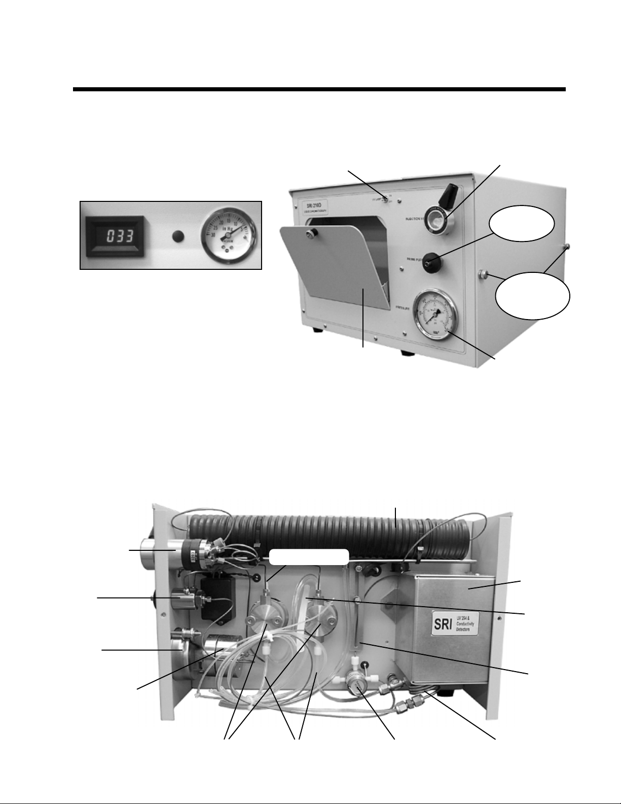
The Model 210D front panel houses the UV detector lamp switch, Rheodyne injection valve, prime/purge
valve, pressure gauge, and the storage
compartment. In the storage compartment
are the LED display for the column
temperature, and the vacuum degas pressure
UV detector
lamp switch
Rheodyne 7725i injection valve
Prime/purge
valve
gauge (shown above). An accessories kit is
included with your 210D. In the kit are two
Column
compartment
thumbscrews
PEEK finger tight nuts (Alltech part # 32233)
for column connection, a spare 1/16”
stainless steel fitting (Valco part ZN1) and
ferrule (Valco part ZF1S6), a flange fitting
Storage
compartment
Pressure gauge
(Upchurch part 203X) and ferrule
(Upchurch part 240X) for the solvent recycle valve, a 20mL priming syringe (Sigma Aldrich part Z248037),
and a 100µL glass injection syringe (SGE part 005300).
On the right hand side of the 210D is the column compartment, which gives you access to the column heater,
pump head(s), solvent recycle valve, and the detector housing. Open the column compartment by loosening
the two captive thumbscrews and lifting off the cover. Use the picture below to familiarize yourself with the
interior of the column compartment.
Column heater
Rheodyne 7725i
injection valve
with a 20µL
sample loop
Prime/purge
valve
Pump outlet line
UV and
Conductivity
detectors
Pressure
gauge
Pulse damper
Vacuum
de-gas
outlet
Vertical
slide
Pump inlet linesPump heads
Solvent recycle valve
Vacuum de-gas coil
Page 2
HPLC
Model 210D
2. Installing a Column
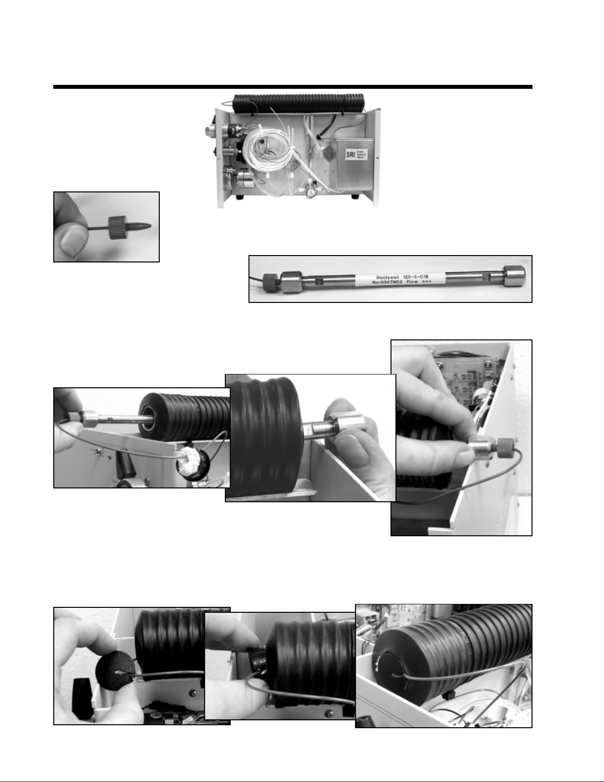
Slide the column heater up.
Install the column of your choice using the included PEEK finger tight nuts. Slide the
nuts onto the PEEK tubing, letting about 1mm of PEEK tubing protrude.
Secure one nut to the column.
Slide the column through the column heater so you can reach the other end,
and attach the second nut. Roughly center the column in the column heater.
Slide the column heater up
on its aluminum slider.
Replace the black column heater end caps, which have notches in them for the PEEK tubing. Pack in any
loose insulation. When you have replaced both end caps as shown below, slide the column heater back down
into the operating position.
Page 3
3. Solvent Set-up
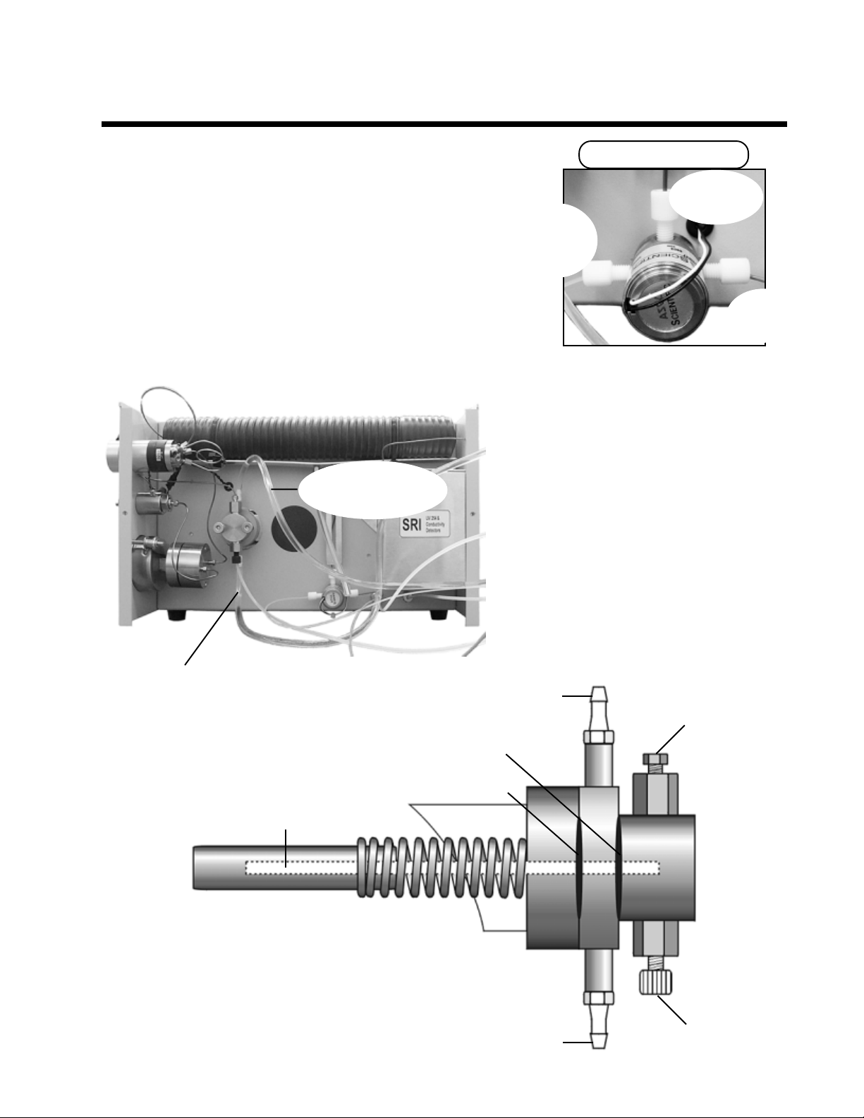
The pump heads each have an 1/8” Teflon solvent inlet line. Place
the ends of these lines in your solvent bottle. The solvent recycle
valve has two outlet lines. The 1/16” clear line is recycled solvent.
Put it into the solvent bottle, or into its own container if you wish
to keep it separate from your fresh solvent. Place the end of the
1/16” green line into a waste bottle. A simplified way to remember:
all the clear lines go to the solvent bottle. In default mode, the
solvent recycling valve sends the effluent out the clear tube; when
activated, it directs the effluent out the green waste tube.
1/4” tygon tubing
piston flush inlet line
HPLC
Model 210D
Solvent recycle valve
Blue = in
from column
Clear =
recycled
solvent out
Green =
to waste
The 1/4” Tygon tubing attached to the pump
head(s) is the piston flush line. Piston flushing
helps keep the high pressure seal(s) clean,
minimizing wear and tear from crystallized and
abrasive buffer deposits that leak through the
seal, and would otherwise dry on the piston.
There are inlet and outlet lines for piston
flushing. Place the ends of both into a bottle
containing at least 50% organic solvent (usually
diluted with deionized water). Binary gradient
pump head piston flush lines are daisy chained,
and share the same in and out lines.
Piston flush
outlet line
210D pump, side view:
It is possible for solvent to leak past
the high pressure seal with the back
and forth thrusting of the piston.
Piston
Piston flush IN
High pressure seal
Low pressure seal
Piston flush OUT
Pump outlet
Pump inlet
Page 4
HPLC
Model 210D
4. Vacuum De-gas
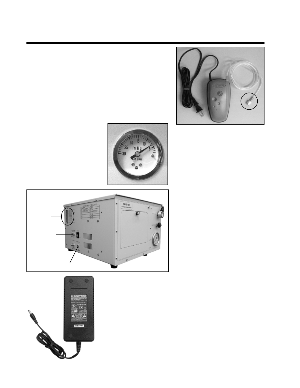
While not all HPLC users degas their solvent, it is a good idea to
do so. The 210D is equipped with an air pump for vacuum
degassing. A length of tygon tubing is provided to connect the
pump to the degas fitting on the left-hand side of the HPLC. The
tubing is equipped with a nut for easy connection to the degas fitting.
With the 210D power ON, connect the pump tubing to the degas
fitting, then plug the pump into a wall outlet. Open the storage
comparment to see the vacuum degas gauge, which should read
7psi with the pump ON and solvent lines attached.
The vacuum degas gauge should
read 7psi during operation.
Simply screw this nut onto the degas fitting
to connect the vacuum pump to the 210D.
Power switch
Access
terminals
Serial or USB
cable to PC
Power supply jack
5. Computer Connection
Connect your 210D to your Windows
TM
computer with the provided serial or USB
cable. The cable connection port is located
on the left-hand side of the 210D.
6. Power Supply
Your 210D comes with a universal (115V or 230V) benchtop 12 volt power
supply (shown at right). Plug the small power source cord into the jack on
the left hand side of the LC. Plug the larger power cord into a wall outlet.
Turn the power ON with the power switch, located above the power supply
jack. The 210D can be powered with any regulated or unregulated voltage
in the range of 11-15 volts at 80 watts (approximately 7 amps), including a
car battery via the cigarette lighter.
Page 5
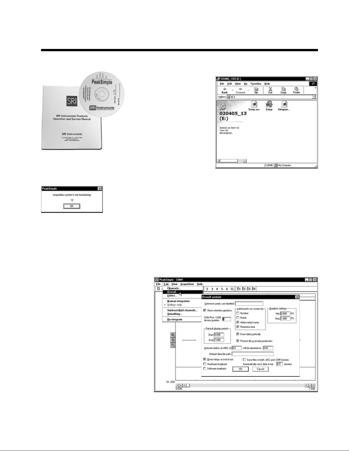
7. Installing PeakSimple software
You will find your PeakSimple
installation disk just inside the
front cover of your manual.
Install the PeakSimple
software by inserting the
PeakSimple CD into the CD-
ROM drive of your Windows
computer. Double-click on My
Computer, then open the CD-ROM
drive. Double-click on the “setup.exe”
program icon and follow the
instructions.
8. Double-click on the PeakSimple icon to launch the program. Verify that
communication is established between the computer and the pump. An error
message (shown at left) will appear if communication is not established.
HPLC
Model 210D
TM
9. Load the LC.CON control file from your PeakSimple program folder. This control file contains all the
necessary information to configure PeakSimple for HPLC.
10. Verify that the correct I/O port is
specified in the Edit/Overall screen. By
default, COM 1 is entered in the Edit/Overall
screen because many Windows
TM
computers have COM 1 designated as the
serial port. Other computers may use COM
2, COM 3, or COM 4. You may have to
examine the My Computer/System screen
to determine what serial port numbers
Windows has assigned to the hardware in
your particular computer. If you upgraded
to the 6 channel USB data system, enter
the USB device ID number in the box
instead.USB device ID numbers are unique
to each instrument, and the number for your
210D is printed on the HPLC under the cable port, and also on your PeakSimple disk. Once you have
successfully gotten the data system to sign on, click Save All so you don’t have to repeat this step the next time
you open PeakSimple.
Page 6
HPLC
Model 210D
11. UV Detector
The UV detector signal is connected to channel 1. The detector uses
Both detectors are housed in the
cell in the middle of this board.
a low volume flow-through cell. The cell temperature is factory set to
o
40
C, which is suitable for a wide range of common applications.
Note for those who have the 4 or 6 channel data system upgrade:
Unless you have connected an external detector to the 210D, the
column temperature will display on channel 3, and the detector cell
temperature will display on channel 4.
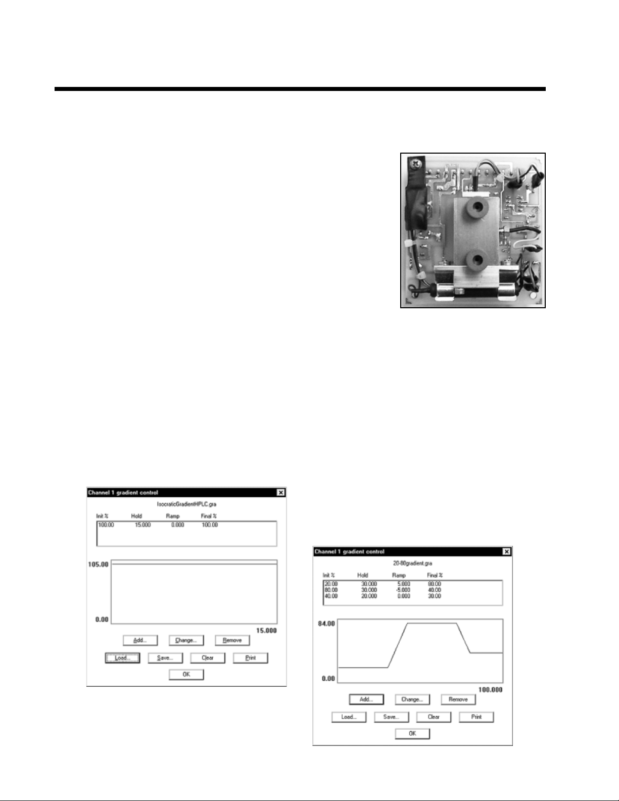
12. Setting a Gradient Program
Click on the Gradient button for channel 1. If your system is isocratic, the Inital and Final percentages are
100%. The only variable is the Hold time period, which is determined by the length of your analytical run.
Setting a gradient program automatically starts the pump at a very low speed. For binary gradient systems,
load a gradient program from your PeakSimple program folder (version 3.19 and later) by clicking on the Load
button in the Channel 1 gradient control window. Use the Add button to create a new gradient.
Isocratic gradient
Binary gradient
Page 7
HPLC
Model 210D
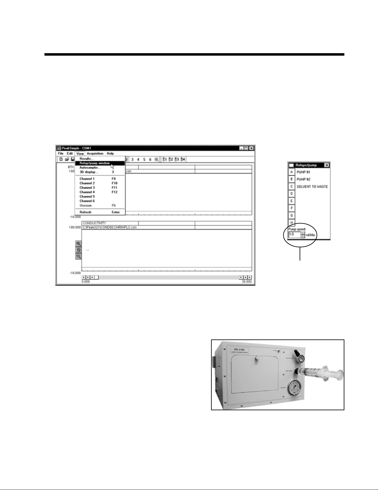
13. Click View and choose Relay/pump window. In the Relays/pump window, click on Relay A to turn the
pump OFF, since you haven’t primed it yet. The flow rate of the pump (pump A in a binary gradient system)
can be adjusted from 0.1 to 5.0mL/minute, in increments of 0.1mL/minute, using the dialog box at the bottom
of the Relays/pump window. In a binary gradient system, the gradient program determines how the flow is split
between the two pumps.
Pump speed
14. Priming the Pump
Note: Do not open the prime/purge valve until pressure is
at zero, or very close. Otherwise, system pressure could
damage the pulse damper or cause the column adsorbent
bed to shift.
Open the prime/purge valve by turning it to the left, then
start the pump by clicking on Relay A in the pump window.
Insert the priming syringe into the prime/purge valve, then
slowly and gently pull back the plunger. When you can pull
a bubble-less stream out of the prime/purge valve, close
the valve by turning it back to the right. The pressure should begin building to operating range, which is
dependent upon the flow rate, solvent viscosity, and the back pressure of the column selected. When the
system stabilizes at the operating pressure range, you may inject your sample. It is normal for the pressure
gauge needle to fluctuate with the pump stroke.
Page 8
HPLC
Model 210D
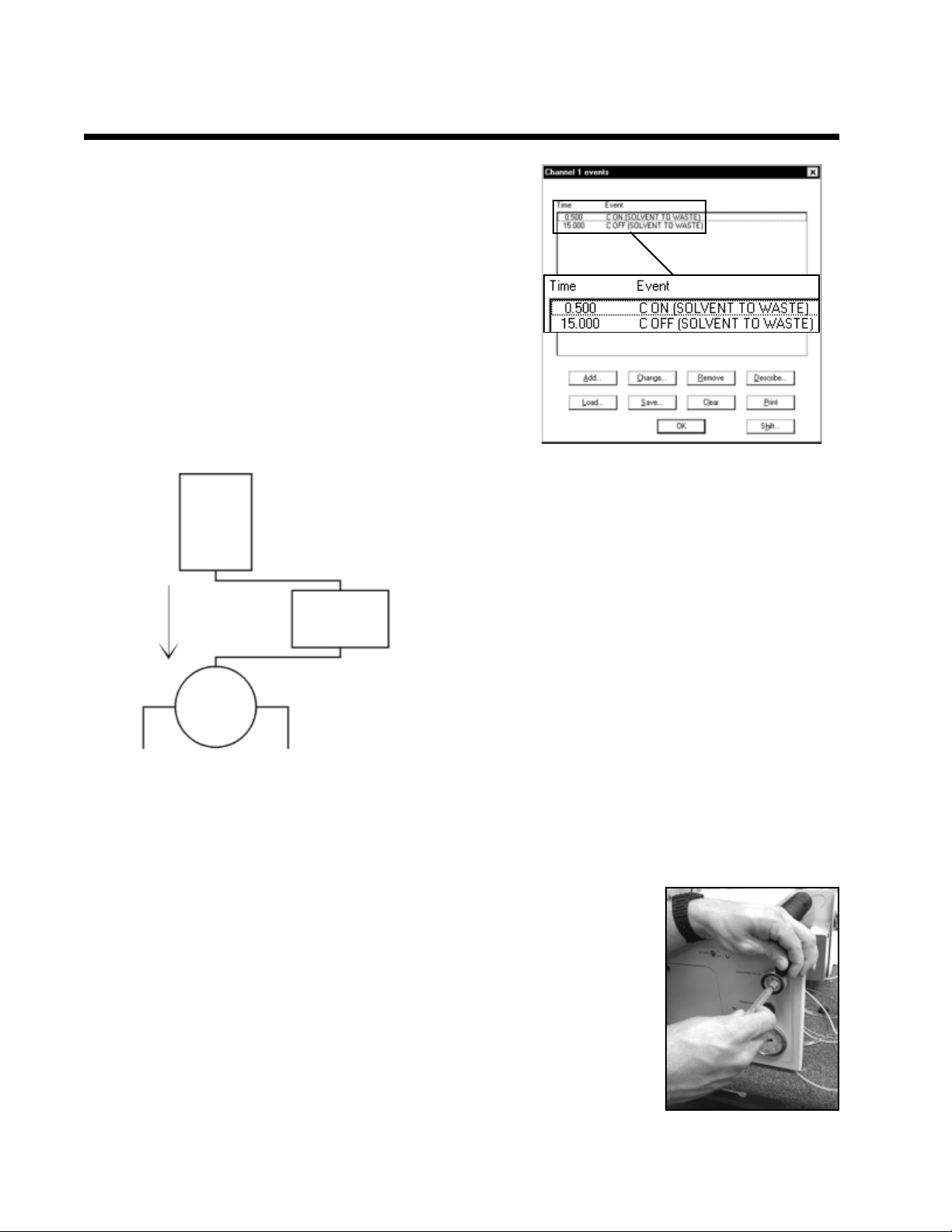
15. Solvent Recycle Control
Relay C controls the solvent recycle valve. When Relay C
is ON, the solvent is directed to waste (green exit tube).
Turn Relay C ON before any peaks appear onscreen, and
turn it OFF at the end of the run. Click on Relay C in the
Relays/pump window to turn it ON and OFF, or use an
event table to do it automatically. The solvent recycle valve
may also be used as a single peak fraction collector by
turning it ON/OFF at specific times during the run.
210D
detector
cell
Example event table for the
solvent recycle valve
The detector exit tube that connects to the top of the
solvent recycle valve may be disconnected, and
External
detector(s)
connected to external detectors, like refractive index or
fluoresence detectors. The external detector’s exit tubes
are then connected back to the solvent recycle valve.
Solvent
recycle
valve
WasteSolvent
16. Injecting a Sample and Starting the Run
The Rheodyne injection valve comes with its own blunt-tipped flushing needle,
which is shipped inserted into the valve under the protective red cap. Remove the
protective cap and tape, then pull out the needle. The provided 100µL glass
injection syringe should suit most injection applications. For the best results, prepare
your sample in the same solvent you are using for your mobile phase. Fill the
syringe with sample, and eliminate any air bubbles. Insert the syringe into the
Rheodyne injection valve, pushing gently until the needle hits the stop. Depress the
syringe plunger to fill the 20µL sample loop. Leave the syringe in the while you turn
the Rheodyne injection valve knob to the INJECT position. The run will
automatically start. See the Rheodyne documentation in your SRI manual under
HPLC Injectors for more information about operating the injection valve.
Page 9
Expected Performance
HPLC
Model 210D
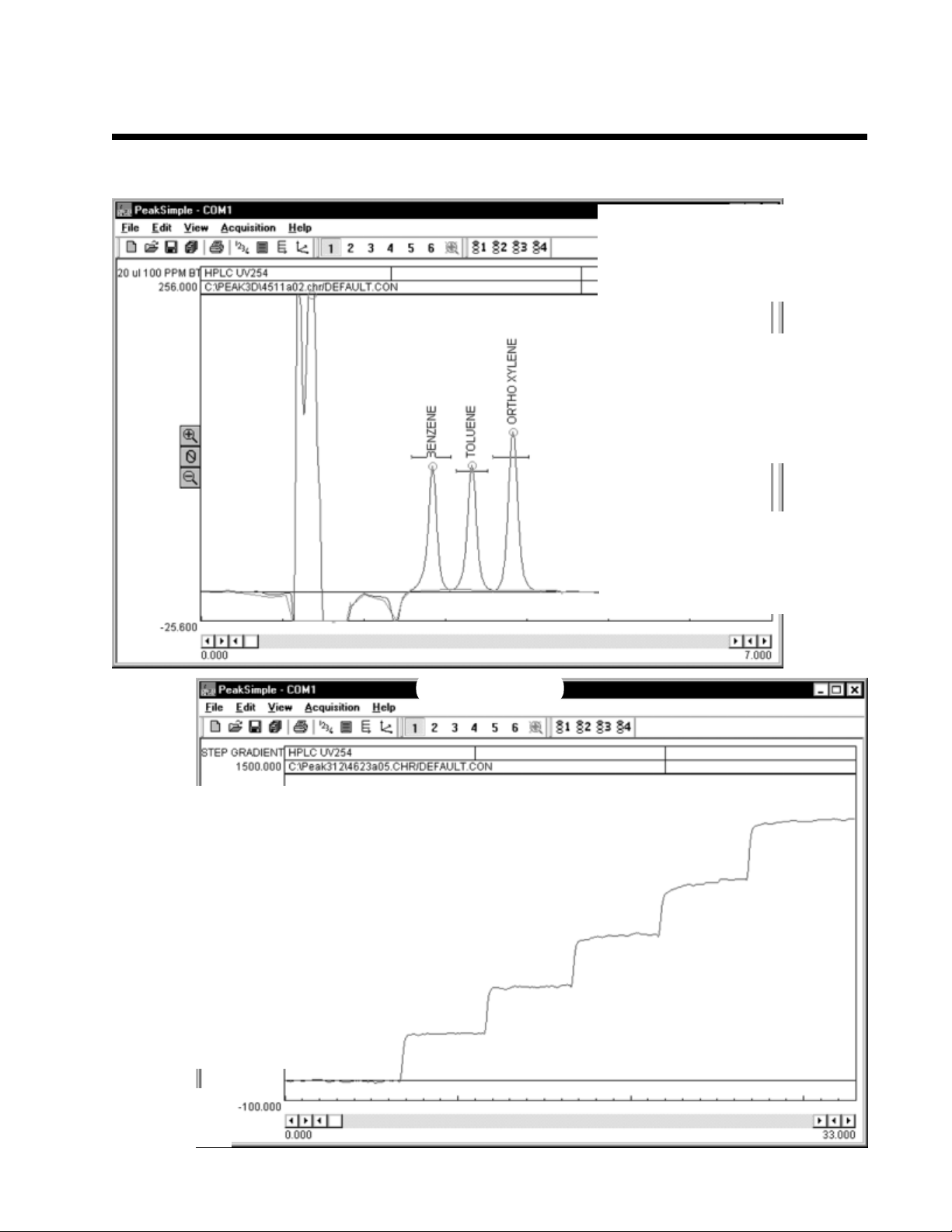
This chromatogram shows the
210D UV detector response to a
BTX sample (benzene, toluene,
and ortho xylene).
Description: UV 254
Sample: 20µL 100ppm BTX
Column: 15cm C18 5µ
Mobile phase: 70% Isopropyl Alcohol,
30% water at 1.0mL/minute
Detector cell temperature: 40oC
Column temperature: 40oC
Pressure: 1300psi
Results:
Component Retention Area
Benzene 2.833 851.1640
Toluene 3.316 912.9170
Ortho Xylene 3.816 1207.1795
Total 2971.2605
Gradient program:
%pumpA Hold Ramp
%pumpB
100.00 5.00 0.00 0.00
80.00 5.00 0.00 20.00
60.00 5.00 0.00 40.00
40.00 5.00 0.00 60.00
20.00 5.00 0.00 80.00
0.00 5.00 0.00 100.00
Description: UV 254
Column: 15cm C18 5µ
Mobile phase: methanol at 2.0mL/minute
Pump A: 100% methanol
Pump B: 99.75% methanol with 0.25%
acetone
Events:
Time Event
0.00 Zero 100
Step Gradient
This chromatogram shows a step gradient
beginning with pump A at 100% and ending
with pump B at 100%. Each of the five
20% steps is held for five minutes.
Page 10
HPLC
Model 210D
Expected Performance
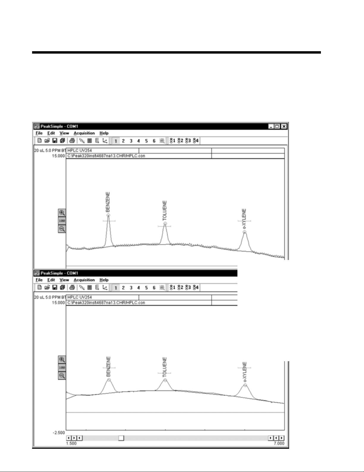
The first chromatogram is a UV separation of 5ppm BTX with an isocratic 210D system. The second
chromatogram shows the same run after using PeakSimple’s data smoothing function. Short term up/down
noise is a function of pump refill. Binary systems are therefore noisier than isocratic systems. PeakSimple’s
smoothing feature can reduce the pump noise for a clearer picture of your data. The data in any channel can be
smoothed automatically using Post-run actions for that channel. See the “PeakSimple Software” section of
your manual for more information.
Description: UV 254
Sample: 20µL 5ppm BTX
Column: 15cm C18 5µ
Mobile phase: 70% Methanol,
30% water at 1.0mL/minute
Detector cell temperature: 40oC
Column temperature: 40oC
Results:
Component Retention Area
Benzene 2.550 26.01
Toluene 3.983 22.69
Xylene 5.983 29.90
Total 78.60
Page 11
HPLC
Model 210D
Expected Performance
UV Detector Noise
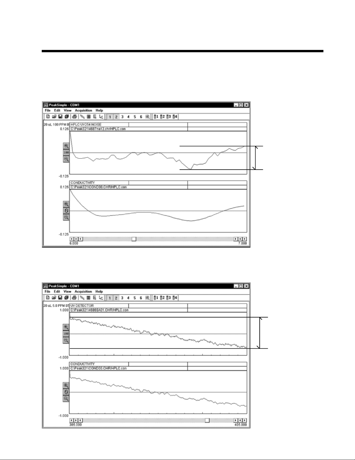
This pair of chromatograms shows a short-term, one minute UV detector noise run on an isocratic 210D
system. The first chromatogram is the raw data, and the second shows it after smoothing.
UV detector noise
averages
approximately
100µV from peak to
peak, or 10
(absorbance units).
-4
a.u.
This pair of raw and smoothed chromatograms shows 20 minutes of a UV detector noise run on an isocratic
210D system. In the longer time segment, the signal drift is visible.
This UV detector
signal drift
averages
approximately
1.3mV in 20
minutes, or
0.0013 a.u.
Page 12
HPLC
Model 210D
General Information
Smoothing: Why Use It?
Short term up/down noise is a function of pump refill. Most other manufacturers smooth data inside detector.
SRI does not, so pump noise is visible. Binary systems are therefore noisier than isocratic systems. PeakSimple’s
smoothing feature can reduce the pump noise so you can more clearly picture your data. Pump noise peaks
are much narrower than data peaks, and do not obscure, esp after smoothing is applied.
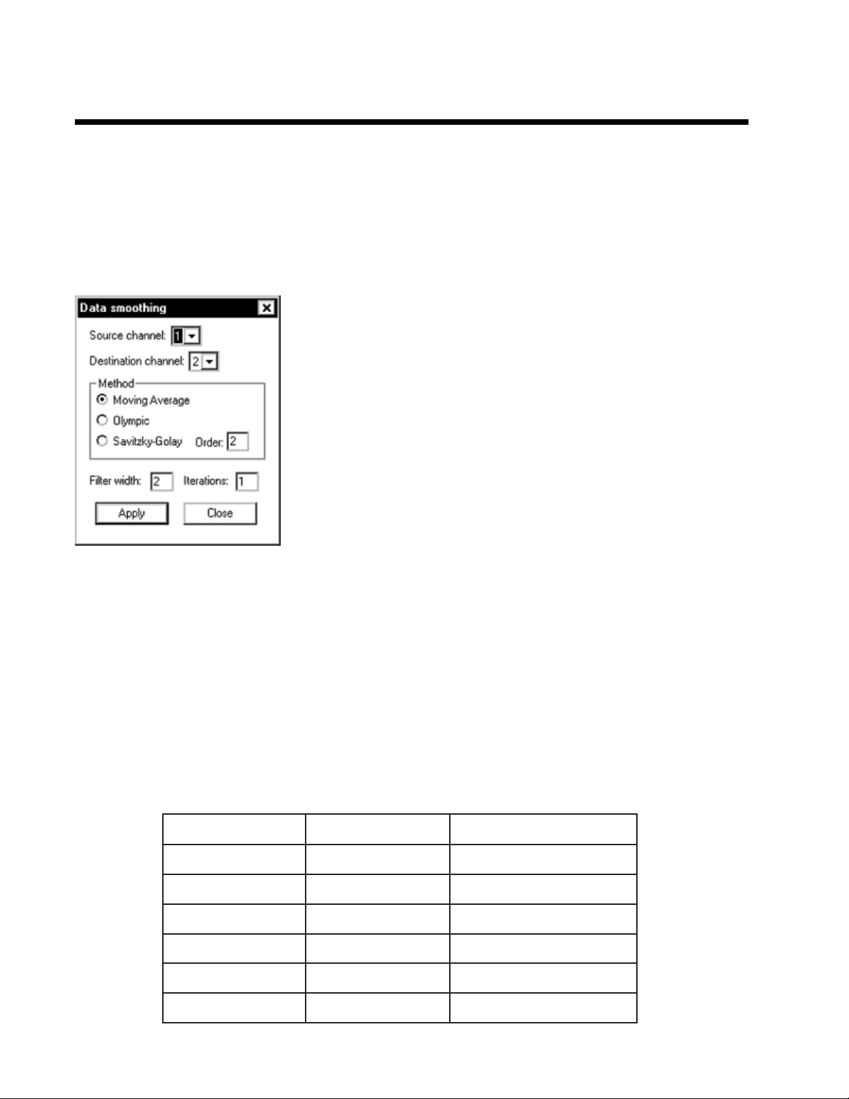
To smooth data, open the chromatogram of your choice in channel 1.
Any channel will work, this is just an example. Open the Data smoothing
window by clicking on the Edit pull-down menu, and choosing
Smoothing... Specify the source channel (the channel in which your
chromatogram is open), then specify the channel in which you want the
smoothed chromatogram to display. Even if you have a single channel
data system, PeakSimple gives you 6 channel screens in which you can
open, compare, and edit your chromatograms. Next, choose one of the
three available smoothing methods by clicking in the radio button beside
it. If you choose Savitzky-Golay, enter the order. Type in the desired
filter width and iterations (you may need to experiment to find the best
combination for your data). Click the Apply button, and your smoothed
chromatogram will appear in the destination channel you designated.
Absorbance VS Transmittance
Other maufacturers make the conversion from transmittance to absorbance in the hardware. To help keep
products affordable and portable, SRI does the conversion through PeakSimple software. With the UV
detector lamp OFF, the data system signal should be at or very close to zero. Click on the Auto Zero button on
the channel 1 chromatogram window to zero the signal at 0% transmittance (0%T). Turn ON the UV lamp
switch. The signal should jump to 3-6mV. This signal is 100% transmittance, or 0 absorbance units. Click on
the Zero 100 button to zero the signal with just the solvent flowing (this is 100% transmission). Keep in mind
that light absorbance is exponential. For example, twice as much toluene does not equal twice as much
absorbance. See the conversion chart below:
ecnattimsnarT%stinuecnabrosbAsgnidaerlangistlovilliM
%0010 Vm0
%011 Vm0001
%12 Vm0002
%1.03 Vm0003
%10.04 Vm0004
%100.05 Vm0005
 Loading...