

Page 1

GEN.0000000005105 Rev B
© 2017 SRAM, LLC
Reverb™ Stealth & Reverb
Hydraulic Hose Replacement
Remote System Bleed
bleed
manual
Page 2

SRAM® LLC WARRANTY
EXTENT OF LIMITED WARRANTY
Except as otherwise set forth herein, SRAM warrants its products to be free from defects in materials or workmanship for a period of two years after
original purchase. This warranty only applies to the original owner and is not transferable. Claims under this warranty must be made through the
retailer where the bicycle or the SRAM component was purchased. Original proof of purchase is required. Except as described herein, SRAM makes
no other warranties, guaranties, or representations of any type (express or implied), and all warranties (including any implied warranties of
reasonable care, merchantibility, or fitness for a particular purpose) are hereby disclaimed.
LOCAL LAW
This warranty statement gives the customer specific legal rights. The customer may also have other rights which vary from state to state (USA), from
province to province (Canada), and from country to country elsewhere in the world.
To the extent that this warranty statement is inconsistent with the local law, this warranty shall be deemed modified to be consistent with such law,
under such local law, certain disclaimers and limitations of this warranty statement may apply to the customer. For example, some states in the United
States of America, as well as some governments outside of the United States (including provinces in Canada) may:
a. Preclude the disclaimers and limitations of this warranty statement from limiting the statutory rights of the consumer
(e.g. United Kingdom).
b. Otherwise restrict the ability of a manufacturer to enforce such disclaimers or limitations.
For Australian customers:
This SRAM limited warranty is provided in Australia by SRAM LLC, 1000 W. Fulton Market, 4th Floor, Chicago, IL, 60607, USA. To make a warranty claim
please contact the retailer from whom you purchased this SRAM product. Alternatively, you may make a claim by contacting SRAM Australia, 6 Marco
Court, Rowville 3178, Australia. For valid claims SRAM will, at its option, either repair or replace your SRAM product. Any expenses incurred in making
the warranty claim are your responsibility. The benefits given by this warranty are additional to other rights and remedies that you may have under
laws relating to our products. Our goods come with guarantees that cannot be excluded under the Australian Consumer Law. You are entitled to a
replacement or refund for a major failure and for compensation for any other reasonably foreseeable loss or damage. You are also entitled to have
the goods repaired or replaced if the goods fail to be of acceptable quality and the failure does not amount to a major failure.
LIMITATIONS OF LIABILITY
To the extent allowed by local law, except for the obligations specifically set forth in this warranty statement, in no event shall SRAM or its third party
suppliers be liable for direct, indirect, special, incidental, or consequential damages.
LIMITATIONS OF WARRANTY
This warranty does not apply to products that have been incorrectly installed and/or adjusted according to the respective SRAM user manual. The
SRAM user manuals can be found online at www.sram.com, rockshox.com, avidbike.com, truvativ.com, or zipp.com.
This warranty does not apply to damage to the product caused by a crash, impact, abuse of the product, non-compliance with manufacturers
specifications of usage or any other circumstances in which the product has been subjected to forces or loads beyond its design.
This warranty does not apply when the product has been modified, including, but not limited to any attempt to open or repair any electronic and
electronic related components, including the motor, controller, battery packs, wiring harnesses, switches, and chargers.
This warranty does not apply when the serial number or production code has been deliberately altered, defaced or removed.
This warranty does not apply to normal wear and tear. Wear and tear parts are subject to damage as a result of normal use, failure to service
according to SRAM recommendations and/or riding or installation in conditions or applications other than recommended.
Wear and tear parts are identified as:
• Dust seals
• Bushings
• Air sealing o-rings
• Glide rings
• Rubber moving parts
• Foam rings
• Rear shock mounting hardware
and main seals
• Upper tubes (stanchions)
• Stripped threads/bolts
(aluminium, titanium, magnesium
or steel)
• Brake sleeves
• Brake pads
• Chains
• Sprockets
• Cassettes
• Shifter and brake cables (inner
and outer)
• Handlebar grips
• Shifter grips
• Jockey wheels
• Disc brake rotors
• Wheel braking surfaces
• Bottomout pads
• Bearings
• Bearing races
• Pawls
• Transmission gears
• Spokes
• Free hubs
• Aero bar pads
• Corrosion
• Tools
• Motors
• Batteries
Notwithstanding anything else set forth herein, the battery pack and charger warranty does not include damage from power surges, use of improper
charger, improper maintenance, or such other misuse.
This warranty shall not cover damages caused by the use of parts of dierent manufacturers.
This warranty shall not cover damages caused by the use of parts that are not compatible, suitable and/or authorised by SRAM for use with SRAM
components.
This warranty shall not cover damages resulting from commercial (rental) use.
Page 3

SAFETY FIRST!
We care about YOU. Please, always wear your safety glasses and
protective gloves when servicing RockShox® products.
Protect yourself! Wear your safety gear!
Page 4

TABLE OF CONTENTS
REVERB™ STEALTH EXPLODED VIEW ...........................................................................................................................................................5
REVERB EXPLODED VIEW ...............................................................................................................................................................................6
ROCKSHOX® SERVICE ........................................................................................................................................................................................7
RECOMMENDED SERVICE INTERVALS .................................................................................................................................................................................................... 7
SERVICE HISTORY ........................................................................................................................................................................................................................................... 7
TORQUE VALUES ............................................................................................................................................................................................................................................. 7
PARTS, TOOLS, AND SUPPLIES ..................................................................................................................................................................................................................8
BICYCLE PREPARATION .....................................................................................................................................................................................9
HYDRAULIC HOSE REPLACEMENT ................................................................................................................................................................11
HYDRAULIC HOSE AND HOSE BARB PREPARATION ........................................................................................................................................................................ 11
REVERB STEALTH HOSE REMOVAL AND INSTALLATION ............................................................................................................................................................... 12
REVERB HOSE REMOVAL AND INSTALLATION ..................................................................................................................................................................................18
HOSE SIZING AND REMOTE INSTALLATION ....................................................................................................................................................................................... 20
REMOTE SYSTEM BLEED ................................................................................................................................................................................ 22
200 Hour Service
REVERB STEALTH REMOVAL ....................................................................................................................................................................................................................22
50/200 Hour Service
REMOTE PREPARATION..............................................................................................................................................................................................................................24
REMOTE SYRINGE PREPARATION .......................................................................................................................................................................................................... 25
200 Hour Service
SEATPOST SYRINGE PREPARATION ...................................................................................................................................................................................................... 26
REMOTE AND SEATPOST BLEED ............................................................................................................................................................................................................ 27
50/200 Hour Service
REMOTE BLEED STANDARD REMOTE.................................................................................................................................................................................................29
REMOTE BLEED REVERB 1X™ REMOTE ...............................................................................................................................................................................................30
200 Hour Service
REVERB STEALTH INSTALLATION .......................................................................................................................................................................................................... 34
50/200 Hour Service
SADDLE, REMOTE, AND BRAKE INSTALLATION ................................................................................................................................................................................ 35
TEST FUNCTION ............................................................................................................................................................................................... 36
Page 5
5Reverb™ Stealth - Exploded View
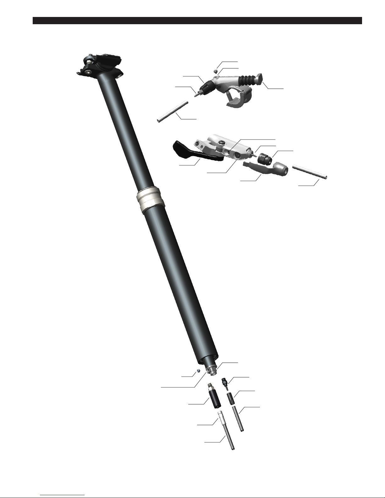
Reverb™ Stealth - Exploded View
Remote Bleed Port
Remote Actuator
Remote Bleed Screw
Speed Adjuster
Remote Hose Barb
Reverb Stealth Bleed Port
Bleed Screw
Connectamajig™ Coupler
Connectamajig Hose Coupler
Reverb Hydraulic Hose
Hose Barb
Poppet Valve Cover
Hose Barb Sleeve
Reverb Hydraulic Hose
Reverb Hydraulic Hose
Reverb Hydraulic Hose
Boot
Remote Hose Barb
Remote Bleed Port
Remote Lever
*REVERB 1X™ REMOTE
STANDARD REMOTE
*Compatible with Reverb Stealth and Reverb
Compression Nut
Speed Adjuster
Page 6
6Reverb™ - Exploded View
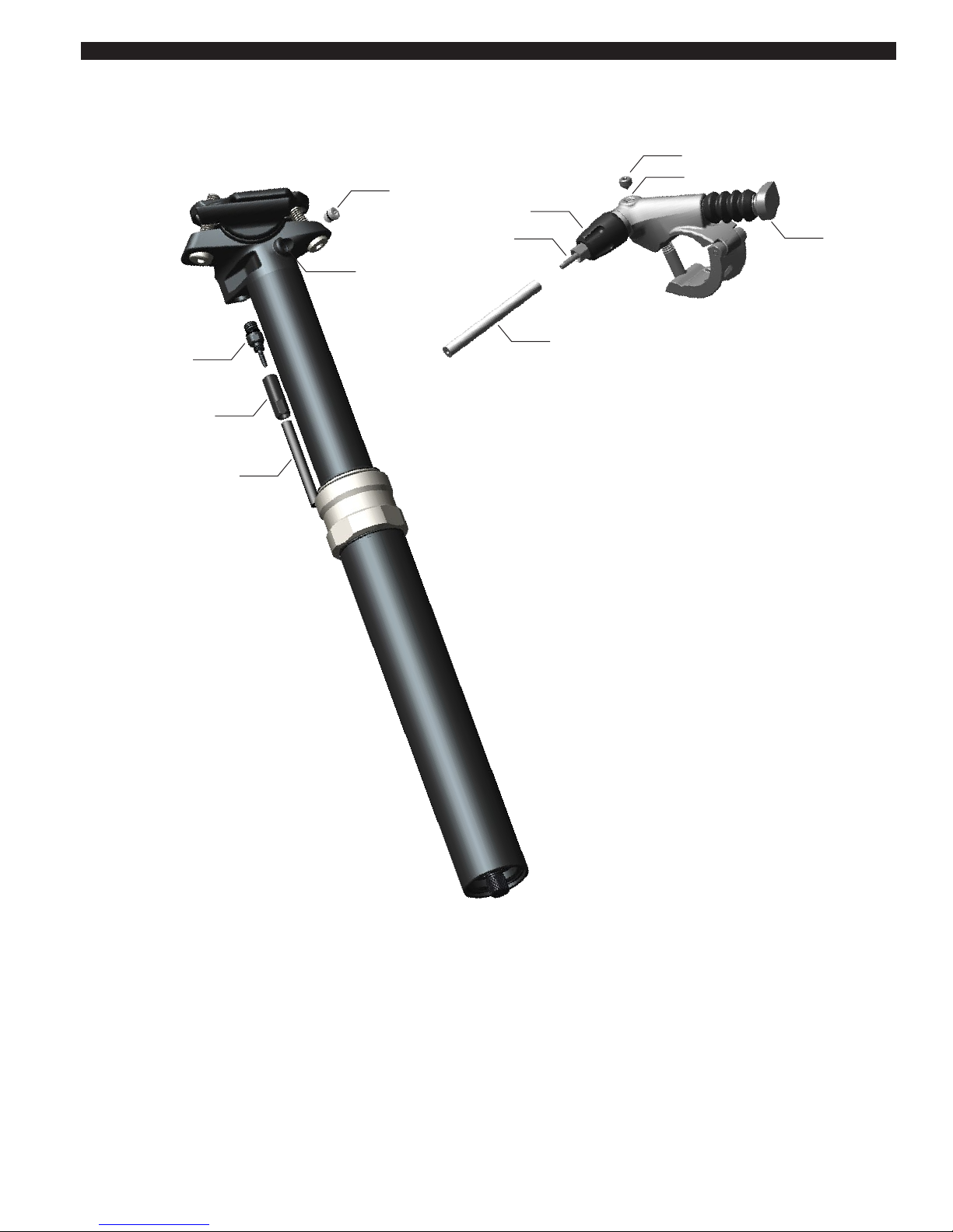
Reverb™ - Exploded View
Hose Barb
Hose Barb Sleeve
Reverb Hydraulic Hose
Remote Bleed Port
Remote
Actuator
Remote Bleed Screw
Speed Adjuster
Remote Hose Barb
Reverb Hydraulic Hose
Post Bleed Screw
Reverb Bleed Port
Page 7
7RockShox® Service
RockShox® Service
We recommend that you have your RockShox suspension serviced by a qualified bicycle mechanic. Servicing RockShox suspension requires
knowledge of suspension components, as well as the use of specialized tools and lubricants.
Visit www.sram.com/service for the latest RockShox Spare Parts catalg and technical information. For order information, please contact your local
SRAM® distributor or dealer.
For recycling and environmental compliance information, please visit www.sram.com.
Information contained in this publication is subject to change at any time without prior notice. Your product's appearance may dier from the pictures
contained in this publication.
Recommended Service Intervals
Service Hours Interval Maintenance
Every ride Clean dirt and debris from seatpost.
Every ride Check remote hydraulic pressure: Standard Remote; Reverb™ 1x™ Remote
As needed Replace the hydraulic hose.
Every 50 Hours Perform remote bleed.
Every 200 Hours Perform remote and seatpost bleed.
Service History
Record each date of service to track service intervals.
Service Hours Interval
50 100 150 200 250 300 350 400
Date of Service
Torque Values
Part Tool Torque
Hose barb / Hose barb sleeve
7 mm open end wrench / Adjustable wrench
3.4-4.5 N•m (30-40 in-lb)
Reverb Stealth poppet cover / Hose barb
10 mm and 7 mm open end wrenches
3.4-4.5 N•m (30-40 in-lb)
Connectamajig™ coupler collar / Hose coupler
9 mm and 6 mm open end wrenches
1.1-2.9 N•m (10-26 in-lb)
Post bleed screw
T10 TORX® wrench
1.1-2.2 N•m (10-20 in-lb)
Remote bleed screw (standard)
T10 TORX wrench
1.1-2.2 N•m (10-20 in-lb)
Remote clamp
T25 TORX wrench
2.8-3.4 N•m (25-30 in-lb)
Seatpost collar
Various
Do not exceed 6.7 N•m (59 in-lb)
Page 8

8
Parts, Tools, and Supplies
Parts
• Reverb™ hydraulic hose kit (Barb or Connectamajig™)
• Reverb Remote Hose Barb kit (optional)
Safety and Protection Supplies
• Apron
• Clean, lint-free rags
• Nitrile gloves
• Oil Pan
• Safety glasses
Lubricants and Fluids
• Friction paste
• Isopropyl alcohol
• RockShox® Reverb hydraulic fluid (included with RockShox Bleed kit)
RockShox Tools
• RockShox Bleeding Edge™ Tool (Reverb 1x™ Remote)
• Reverb Stealth Barb Connector
• RockShox Bleed kit
Bicycle Tools
• Bicycle work stand
• Hydraulic hose cutter
Tools
• 3, 4 mm hex wrenches
• 4 mm hex bit socket
• 6, 7, 9, 10 mm open end wrenches
• 7, 9, 10 mm crowfoot sockets
• Adjustable open end wrench
• Marker
• Needle nose pliers
• Plastic cable tie
• T10 and T25 TORX® bit sockets
• T10 and T25 TORX wrenches
• Torque wrench
SAFETY INSTRUCTIONS
Always wear safety glasses and nitrile gloves when working with suspension lubricants and fluids.
Place an oil pan under the product during service.
NOTICE
Before beginning service, thoroughly clean the exterior of the product to avoid contamination of internal sealing part surfaces.
When using a crowfoot socket and torque wrench, install the crowfoot socket at 90 degrees to the torque wrench.
Ensure there are no sharp bends in the hydraulic hose. A sharp bend in the hose will prevent fluid from flowing.
⚠ WARNING
Do not allow Reverb hydraulic fluid to come into contact with disc brake levers, calipers, pads, rotors, or braking surfaces. If hydraulic fluid contacts
brake pads, the brake pads must be replaced. Use isopropyl alcohol to remove hydraulic fluid from any brake or braking surface. Failure to remove
hydraulic fluid from brakes and braking surfaces can damage components and reduce brake performance, and may result in serious injury and/or
death to the rider. Remove brake components before performing hose replacement and hydraulic remote bleed procedures.
Page 9

9Bicycle Preparation
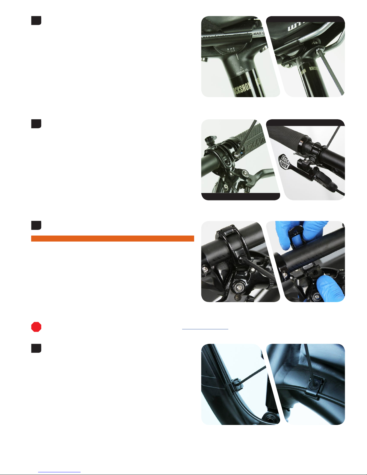
Bicycle Preparation
Secure the bicycle in an upright position.
Reverb™ Stealth: The seatpost will be removed from the
bicycle. Do not clamp the seatpost in a bicycle work stand.
Raise the seatpost to the fully extended position.
Set the speed adjuster to the full slow position.
Rotating the speed adjuster to the slowest setting is critical for a
successful bleed. Failure to do so may result in insucient fluid
volume inside the hydraulic remote system.
Standard Remote: Turn the speed adjuster knob in the opposite
direction of the arrow (counter-clockwise) until it stops.
Reverb 1x Remote: Remove the remote boot and rotate it out of the
way. Turn the speed adjuster bolt (counter-clockwise) until it stops.
1
2
Standard Remote
Reverb 1x™ Remote
3
Standard Remote
T25 TORX® 1x Remote
Page 10
10Bicycle Preparation
Record your saddle settings.
Remove the saddle clamps and saddle.
Remove the remote lever assembly from the handlebar.
Reverb™ 1x™ Remote: The 1x remote may be attached to the handlebar
with a discrete clamp. If the 1x remote is attached to MatchMaker™
X and a SRAM® brake lever and clamp (pictured), the 1x remote and
brake lever will both be removed at this time.
Hydraulic Disc Brakes: Remove each brake lever and brake caliper to
avoid Reverb hydraulic fluid and DOT brake fluid cross contamination.
⚠ WARNING
Do not allow Reverb hydraulic fluid to come into contact with any brake
components. Contaminated brake components can compromise brake
performance, may cause brake failure, and can lead to serious injury
and/or death.
To continue with the remote system bleed procedure, proceed to Remote System Bleed.
Disconnect the hydraulic hose from the frame.
4
4 mm
5
T25 TORX® Standard Remote
4 mm or T25 Reverb 1x Remote
6
7
Page 11
11Hydraulic Hose Replacement
Hydraulic Hose Replacement
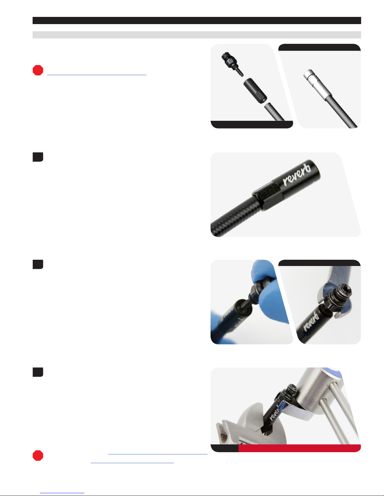
Hydraulic Hose and Hose Barb Preparation
A new Reverb™ hose kit with a hose barb must be assembled.
A new Reverb hose kit with Connectamajig™ does not require assembly.
Reverb Hydraulic Hose kit with Connectamajig: Proceed to
Reverb Stealth Hose Removal and Installation.
Install the barb sleeve onto the hose.
Install the o-ring onto the barb.
Thread the barb into the hose and barb sleeve until it stops.
Tighten the hose barb and barb sleeve.
Reverb Stealth: Proceed to Reverb Stealth Hose Removal and Installation.
Reverb: Proceed to Reverb Hose Removal and Installation.
Hose with Hose Barb
Hose with Connectamajig
1
2
7 mm or T10 TORX®
3
7 mm 1.1-2.2 N•m (10-20 in-lb)
Page 12

12Reverb™ Stealth Hose Removal and Installation
Reverb™ Stealth Hose Removal and Installation
Loosen the seatpost collar.
Remove the seatpost and push the hydraulic hose into the frame.
NOTICE
Do not pull the seatpost out of the frame if there is tension at the hose.
This can cause damage to the hydraulic hose and hose barb.
Place a rag under the seatpost and hose to absorb any fluid.
Clamp the seatpost into a bicycle work stand.
1
2
Hose Port - Head Tube
Hose Port - Seat Tube
3
Page 13

13Reverb™ Stealth Hose Removal and Installation
Hose Barb: Remove the hose barb.
Connectamajig™ Hose Coupler: Remove the hose coupler.
Use a rag to wipe away any fluid.
Cut the hydraulic hose.
Use a rag to collect any fluid that may drip.
Thread the Reverb™ Stealth Barb Connector tool, reverse threaded end
first, into the hose.
4
10 mm 7 mm
Hose Barb
9 mm 6 mm
Connectamajig Hose Coupler
5
Hydraulic Hose Cutter Hose Barb
Hydraulic Hose Cutter Connectamajig
6
Reverb Stealth Barb Connector Tool
Small Hex Wrench
Page 14

14Reverb™ Stealth Hose Removal and Installation
Thread the end of the new hose onto the other end of the Barb
Connector tool to connect the hoses.
Pull the original hose out of the frame and insert the new hose into the
frame.
The original hose is used to pull the new hose through the bicycle
frame and out of the hose port.
Stop when the new hose barb or Connectamajig™ hose coupler is
above the seat tube.
7
8
Page 15

15Reverb™ Stealth Hose Removal and Installation
Hose barb: Install the hose barb into the seatpost and tighten.
Connectamajig™ Hose Coupler: Install the hose coupler into the
coupler and tighten.
Remove the seatpost from the bicycle work stand.
Apply friction paste to the outside of the seatpost.
Install the seatpost and pull the hose through the frame.
⚠ WARNING
Failure to use friction paste could allow the seatpost to slip during use,
which could lead to serious injury and/or death.
9
10 mm 3.4-4.5 N•m (30-40 in-lb) 7 mm
9 mm 1.1-2.9 N•m (10-26 in-lb) 6 mm
10
Page 16

16Reverb™ Stealth Hose Removal and Installation
Position the seatpost at the desired ride height and tighten the
seatpost collar.
The seatpost will be tightened to the correct torque after the bleed
procedure is complete.
Secure the hose to the frame.
Unthread and remove the original hose and Reverb™ Stealth Hose
Connector tool from the new hose.
11
12
13
Reverb Stealth Hose Connector Tool
Page 17

17Reverb™ Stealth Hose Removal and Installation
Unthread and remove the remote from the original hose.
Reverb™ Stealth: Proceed to Hose Sizing and Remote Installation.
14
Needle nose pliers Standard Remote
Needle nose pliers Reverb 1x™ Remote
Page 18

18Reverb™ Hose Removal and Installation
Reverb™ Hose Removal and Installation
Wrap a rag around the upper post.
Remove the hose barb.
Remove the hose from the frame.
1
2
7 mm
3
Page 19

19Reverb™ Hose Removal and Installation
Hold the hydraulic hose near the hose barb. Rotate the Reverb™ remote
lever counterclockwise and unthread the hose from the remote hose
barb.
Discard the hose.
Install the new hose barb and hose, and tighten to.
Secure the hose to the frame.
4
Needle nose pliers
5
7 mm 3.4-4.5 N•m (30-40 in-lb)
6
Page 20

20Hose Sizing and Remote Installation
Hose Sizing and Remote Installation
With the seatpost fully extended and at the desired ride height in the
frame, route the hose to the handlebar remote location.
Hold the hose and turn the handlebar side to side.
The proper length of the hose should create a gentle bend and allow
the handlebar to turn side to side.
NOTICE
Ensure there are no sharp bends in the hydraulic hose. A sharp bend in
the hose will prevent fluid from flowing.
Ensure there is no tension at the remote when the bar is turned. Too
much tension will cause the hose to disconnect from the remote.
1
Reverb™ Stealth
Reverb
2
Page 21

21Hose Sizing and Remote Installation
Mark the cut location.
Cut the hydraulic hose.
NOTICE
To ensure a square cut and to prevent damage to the hose, use only a
hydraulic hose cutter.
Thread the remote lever hose barb into the hydraulic hose. Hold the
end of the hose and rotate the remote lever clockwise while pushing
the remote lever barb into the hose. Stop when the hose is hand tight
on the hose barb.
NOTICE
Do not over-tighten and strip the threads inside the hydraulic hose. If
the hose is over or under tightened, hydraulic fluid can leak.
This concludes the hose replacement procedure for the RockShox®
Reverb™ Stealth and Reverb adjustable height seatposts.
The hydraulic remote system must be bled after a new hose is installed. Proceed to Remote System Bleed.
Reverb 1x™ Remote Upgrade Kit: The Reverb 1x Remote upgrade lever
does not contain hydraulic fluid. The hydraulic remote system must be
bled after a new Reverb 1x Remote lever is installed for the first time.
Proceed to Remote System Bleed.
3
Marker
4
Hydraulic Hose Cutters
5
Needle nose pliers Standard Remote
Reverb 1x Remote
Needle nose pliers
Page 22

22Remote System Bleed
Remote System Bleed
If the seatpost will not compress or extend when the remote actuator is depressed, check the hydraulic hose connections for leaking hydraulic fluid.
Tighten the hose connections as needed before performing the remote and seatpost bleed procedure.
Complete Bicycle Preparation before beginning the Remote System Bleed.
Reverb™ 1x™ Remote Upgrade Kit: The 1x Remote upgrade lever does not contain hydraulic fluid. The hydraulic remote system must be bled after a
new 1x Remote lever is installed for the first time. Refer to Hose Sizing and Remote Installation - Step 5 for 1x Remote installation.
Reverb: Proceed to Remote Preparation.
⚠ WARNING
Do not allow Reverb hydraulic fluid to come into contact with any brake components. Contaminated brake components can compromise brake
performance, may cause brake failure, and can lead to serious injury and/or death.
200 Hour Service Reverb Stealth Removal
Disconnect the hose from the frame.
Loosen the seatpost collar.
1
2
Page 23

23Reverb Stealth Removal
Remove the seatpost and push the hydraulic hose into the frame.
NOTICE
Do not pull the seatpost out of the frame if there is tension at the hose.
This can cause damage to the hydraulic hose and hose barb.
Secure the seatpost to the rear wheel with the bleed port oriented
upward.
Place a rag under the seatpost.
NOTICE
Ensure there are no sharp bends in the hydraulic hose. A sharp bend in
the hose will prevent fluid from flowing.
3
Hose Port - Head Tube
Hose port - seat tube
4
Plastic Cable Tie
Page 24

24Remote Preparation
50/200 Hour Service Remote Preparation
Install and orient the remote on the handlebar with the bleed port level,
or at the highest point.
Set the speed adjuster to the full slow position.
Rotating the speed adjuster to the slowest setting is critical for a
successful bleed. Failure to do so may result in insucient fluid
volume inside the hydraulic remote system.
Turn the speed adjuster in the opposite direction of the arrow (counterclockwise) until it stops.
1
T25 TORX® Standard Remote
Reverb™ 1x™ Remote
2
Standard Remote
T25 TORX Reverb 1x Remote
Page 25

25Remote Syringe Preparation
50/200 Hour Service Remote Syringe Preparation
Install the Bleeding Edge™ syringe bleed tool onto one RockShox®
syringe.
Draw 20 mL of Reverb™ hydraulic fluid into the syringe.
Hold the syringe upright, cover the tip with a rag, and gently depress
the plunger to purge any air bubbles from the syringe.
NOTICE
Only use the syringes included with the RockShox Bleed kit.
Do not use syringes that have been in contact with DOT brake fluid.
DOT brake fluid will permanently damage the seals and cause the
seatpost to malfunction.
Standard Remote: Remove the bleed screw and thread the standard
syringe bleed fitting into the remote bleed port.
Reverb 1x Remote: To open the system, turn the bleed port screw
counter-clockwise one quarter turn. Then turn the bleed port screw
clockwise until light resistance is felt, then stop.
The bleed port must be opened with a hex wrench the first time it is
opened.
Insert the Bleeding Edge syringe bleed fitting into the remote bleed
port, and push down until the 3 mm hex end is engaged with the bleed
port. Turn the bleed fitting 1/4 to 1 full turn counter-clockwise to open
the bleed system.
Standard Remote Bleed: Proceed to Remote Bleed - Standard.
Reverb 1x Remote Bleed: Proceed to Remote Bleed - Reverb 1x Remote.
1
Standard Remote - Standard Syringe
Reverb 1x™ Remote - Bleeding Edge Syringe
2
T10 TORX® Standard Remote
3 mm Hex Reverb 1x Remote
Bleeding Edge Tool Reverb 1x Remote
Page 26

26Seatpost Syringe Preparation
200 Hour Service Seatpost Syringe Preparation
Draw 5 mL of fluid into the second RockShox® bleed syringe.
Hold the syringe upright, cover the tip with a rag, and gently depress
the plunger to purge any air bubbles from the syringe.
NOTICE
Only use the syringes included with the RockShox Bleed kit.
Do not use syringes that have been in contact with DOT brake fluid.
DOT brake fluid will permanently damage the seals and cause the
seatpost to malfunction.
Wrap a rag around the seatpost.
Remove the bleed screw.
Install the syringe into the seatpost bleed port.
1
Bleed Syringe Reverb™ Hydraulic Fluid - 5 mL
22 mm
2
T10 TORX® Reverb Stealth
T10 TORX Reverb
Page 27

27Remote and Seatpost Bleed
200 Hour Service Remote and Seatpost Bleed
Depress the remote syringe plunger while pulling the seatpost syringe
plunger out.
NOTICE
Do not empty the syringe. Leave at least 5 mL of fluid in each syringe
during the procedure to avoid air entering the system.
Depress the seatpost syringe plunger while pulling the remote syringe
plunger out.
Repeat Steps 1 and 2 several times until bubbles are no longer pulled
from the remote and seatpost.
Standard Remote - Standard Syringe
Reverb 1x™ Remote - Bleeding Edge™ Syringe
1
Reverb™ Stealth - Seatpost
Reverb - Seatpost
2
Reverb Stealth - Seatpost
Reverb - Seatpost
Standard Remote
Reverb 1x Remote
Page 28

28Remote and Seatpost Bleed
Remove the syringe.
Install the bleed screw and tighten.
Spray isopropyl alcohol on the seatpost and hydraulic hose and clean
them with a rag.
Reverb 1x™ Remote Bleed: Proceed to Remote Bleed - Reverb 1x Remote.
3
Reverb™ Stealth
T10 TORX® 1.1-2.2 N•m (10-20 in-lb)
Reverb
T10 TORX 1.1-2.2 N•m (10-20 in-lb)
Page 29

29Remote Bleed - Standard Remote
50/200 Hour Service Remote Bleed - Standard Remote
Pull up on the syringe plunger and push the remote actuator.
Depress the syringe plunger until the actuator fully extends.
Repeat this process until bubbles are no longer pulled from the remote
into the syringe.
Depress the plunger once more and make sure the remote actuator is
fully extended.
Remove the syringe.
Install the bleed screw and tighten.
Spray isopropyl alcohol on the remote and clean it with a rag.
Test remote hydraulic pressure: Depress and release the actuator five
times to allow the actuator to return to the fully extended position.
Pull back on the actuator. If the actuator does not move, the bleed was
successful and is complete. If the actuator can be pulled back, fluid
volume and pressure are insucient and the Remote and Seatpost
Bleed procedure must be repeated.
Confirm fluid is not leaking from either end of the hose when the
actuator is depressed. If a leak is detected, the hose must be tightened
and the bleed procedure may need to be repeated.
When the bleed is complete, remove the remote from the handlebar.
Reverb™ Stealth: Proceed to Reverb Stealth Installation.
Reverb: Proceed to Saddle, Remote, and Brake Installation.
1
2
T10 TORX® 1.1-2.2 N•m (10-20 in-lb)
3
Page 30

30Remote Bleed - Reverb™ 1x™ Remote
50/200 Hour Service Remote Bleed - Reverb™ 1x™ Remote
While applying light opposing pressure to the syringe body, slowly pull
up on the syringe plunger to draw a vacuum. Hold the plunger in the
extended drawn position.
Air bubbles may be drawn into the syringe. This is normal.
NOTICE
Do not pull the syringe plunger without applying opposing pressure
to the syringe body. Excessive pulling will pull the syringe Bleeding
Edge™ fitting out of the remote lever.
While holding the sryinge plunger extended with a vacuum drawn,
slowly press the remote lever once.
Hold the lever down; do not release.
Air bubbles will exit the lever and enter the syringe.
While holding the lever down, release the syringe plunger to release
the vacuum inside the syringe.
With the remote lever pressed down, apply light pressure to the
syringe plunger and push fluid into the remote.
NOTICE
Do not push the syringe plunger with excessive force. The syringe
bleed fitting may be forced out of the lever body if fluid exceeds the
bleed fitting-remote coupling strength.
1
Reverb 1x Remote - Bleeding Edge Syringe
2
3
Page 31

31Remote Bleed - Reverb™ 1x™ Remote
Slowly push the syringe plunger down while simultaneously slowly
releasing the remote lever, applying light opposing pressure on the
lever, then release pressure from the syringe.
Do not release pressure from the remote lever until it is fully extended.
When the remote lever is fully extended, release pressure from the
syringe.
Repeat this process (steps 1 through 4) five to six times, until no
bubbles, or very few bubbles, are visible exiting the lever.
Air bubbles will be visible exiting the remote during this process.
While pressing down lightly, turn the Bleeding Edge™ tool clockwise
until it stops. Turn the tool with a moderate amount of additional torque
to close the bleed port.
Hold the wings on the Bleeding Edge tool to apply torque while
turning.
The system is now closed.
While applying light opposing pressure to the syringe body, slowly pull
up on the syringe plunger to draw a vacuum.
Hold the plunger in the extended drawn position.
NOTICE
Do not pull the syringe plunger without applying opposing pressure
to the syringe body or Bleeding Edge tool. Excessive force will pull
the bleed fitting out of the remote lever
4
5
Bleeding Edge Tool
6
Page 32

32Remote Bleed - Reverb™ 1x™ Remote
With the syringe plunger extended, hold the Bleeding Edge™ tool and
gently but firmly, remove it from the bleed port.
NOTICE
Do not pull the syringe or hose. This could cause separation and loss
of fluid.
Do not rock the Bleeding Edge tool side to side. This could damage the
tool and remote.
Absorb and remove any excess fluid from the bleed port with a rag.
Test remote hydraulic pressure: Press and release the remote lever
five or six times and confirm the lever retracts slowly and smoothly with
no gaps in pressure.
Observe the bleed port. If fluid leaks from the bleed port when the
lever is pressed and released, the bleed port is not closed properly. If
fluid is visible, insert the Bleeding Edge tool and tighten the bleed port
before proceeding.
Confirm fluid is not leaking from either end of the hose when the
actuator is depressed. If a leak is detected, the hose must be tightened
and the bleed procedure may need to be repeated.
Turn the speed adjuster clockwise until it stops. This is the fastest
speed setting.
7
Bleeding Edge Tool
8
9
10
T25 TORX®
Page 33

33Remote Bleed - Reverb™ 1x™ Remote
Rotate the remote boot, insert each plug into each hole, and press it
back into place.
Clean the remote with isopropyl alcohol and a rag as needed.
Reverb™ Stealth: Proceed to the next page.
Reverb: Proceed to Saddle, Remote, and Brake Installation.
11
Page 34

34Reverb Stealth Installation
200 Hour Service Reverb Stealth Installation
Cut the cable tie and remove the seatpost from the rear wheel.
Apply friction paste to the seatpost.
Install the seatpost and pull the hydraulic hose through the frame.
⚠ WARNING
Failure to use friction paste could allow the seatpost to slip during use,
which could lead to serious injury and/or death.
Set the seatpost to the desired ride height in the bicycle and tighten
the seatpost collar to the frame manufacturer's recommended torque,
but do not exceed 6.7 N•m (59 in-lb).
NOTICE
If the seatpost collar torque exceeds 6.7 N•m (59 in-lb), the seatpost
will not function properly.
Secure the hose to the frame.
1
Hose Port - Head Tube
Hose Port - Seat Tube
2
≤ 6.7 N•m (59 in-lb)
3
Page 35

35Saddle, Remote, and Brake Installation
50/200 Hour Service Saddle, Remote, and Brake Installation
Install the saddle clamps and saddle, and tighten the bolts.
Install each brake lever and caliper according to the brake
manufacturer's recommended procedures.
Reverb™ 1x™ Remote: Adjust the brake and remote to the desired
position and tighten the clamp bolt.
The Reverb 1x remote can be attached to the handlebar with the
included discrete clamp if the brake lever is not compatible with
SRAM® MatchMaker™ X.
Standard Remote: Install the remote in the desired position and tighten
the clamp bolt.
1
4 mm 8-10 N•m (70-89 in-lb)
2
T25 TORX® 3.0-4.0 N•m (35-44 in-lb) Reverb 1x Remote
3
T25 TORX 2.8-3.4 N•m (25-30 in-lb) Standard
Page 36

36Test Function
Test Function
Press the remote actuator and push the seatpost down by hand.
The seatpost should compress when the remote actuator is depressed
and weight is applied to the saddle.
Press the remote actuator again. The seatpost should return to full
extension when the remote actuator is depressed and weight is
removed from the saddle.
If the seatpost does not compress or extend, the remote hydraulic
volume and pressure may be insucient. Repeat the Remote and
Seatpost Bleed procedure.
Standard Remote
Reverb™ 1x™ Remote
1
Standard Remote
Reverb 1x Remote
Page 37

37Test Function
Adjust the speed adjuster to the desired setting and repeat step 1.
Adjust as desired.
Reverb™ 1x™ Remote: Reinstall the boot onto the lever.
This concludes the bleed procedure for the RockShox® Reverb Stealth and Reverb adjustable height seatposts.
2
Standard Remote
T25 TORX® Reverb 1x Remote
Page 38

This publication includes trademarks and registered trademarks of the following companies:
TORX® is a registered trademark of Acument Intellectual Properties, LLC.
Page 39

ASIAN HEADQUARTERS
SRAM Taiwan
No. 1598-8 Chung Shan Road
Shen Kang Hsiang, Taichung City
Taiwan R.O.C.
WORLD HEADQUARTERS
SRAM LLC
1000 W. Fulton Market, 4th Floor
Chicago, Illinois 60607
USA
EUROPEAN HEADQUARTERS
SRAM Europe
Paasbosweg 14-16
3862ZS Nijkerk
The Netherlands
www.sram.com
 Loading...