

Page 1
User Manual
95-3018-014-000 Rev B © 2017 SRAM, LLC
Page 2

Table of Contents
Tools and Supplies .................................. 4
ShockWiz .................................................5
ShockWiz - Direct Mount ....................... 7
Battery ...................................................... 9
Mounting Boot Installation .................. 13
Front Suspension .................................. 14
Rear Suspension ...................................32
ShockWiz App Set Up ..........................42
Calibration Wizard ................................54
Ride Session ..........................................60
Removal ..................................................71
Maintenance ..........................................72
2
2
Page 3

ShockWiz™ is not compatible with
all air suspension forks and rear
shocks. For more information,
please visit www.shockwiz.com.
ShockWiz firmware must be
updated after each app update.
Use the ShockWiz app to update
device firmware.
The ShockWiz app is available in
iOS® and Android® formats.
For regulatory compliance, please
visit www.shockwiz.com.
For recycling and environmental
compliance information, please visit
www.sram.com.
3
3
Page 4
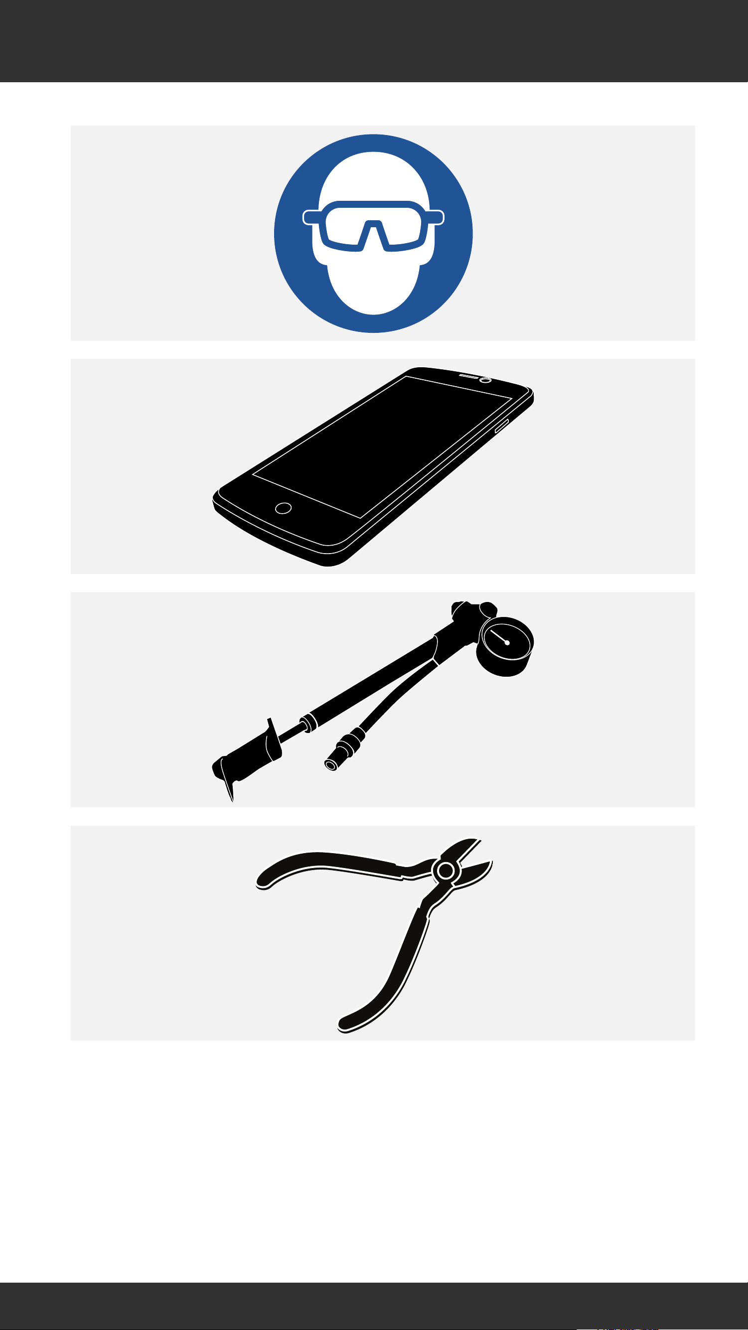
Tools and Supplies
4
4
Page 5
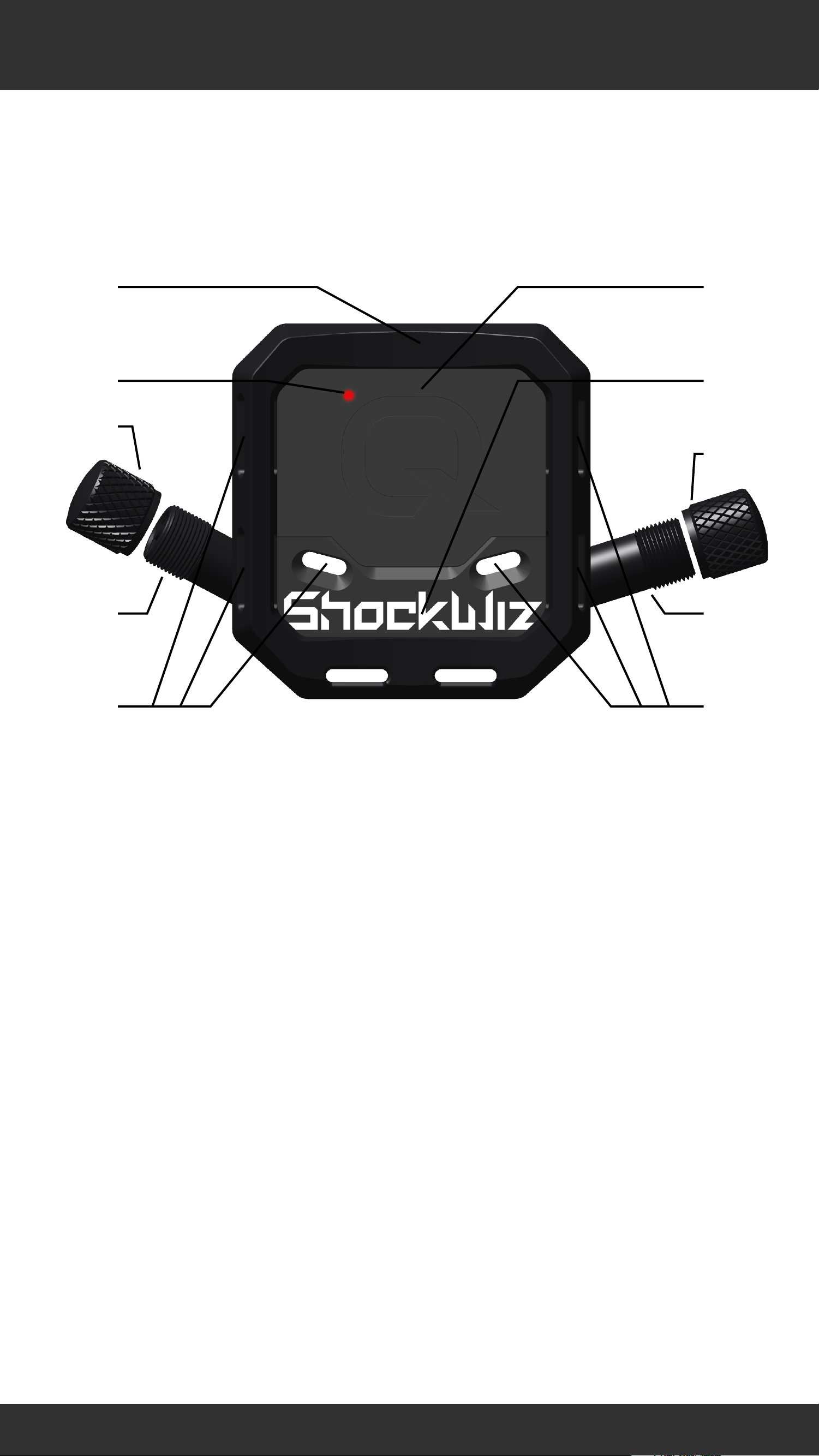
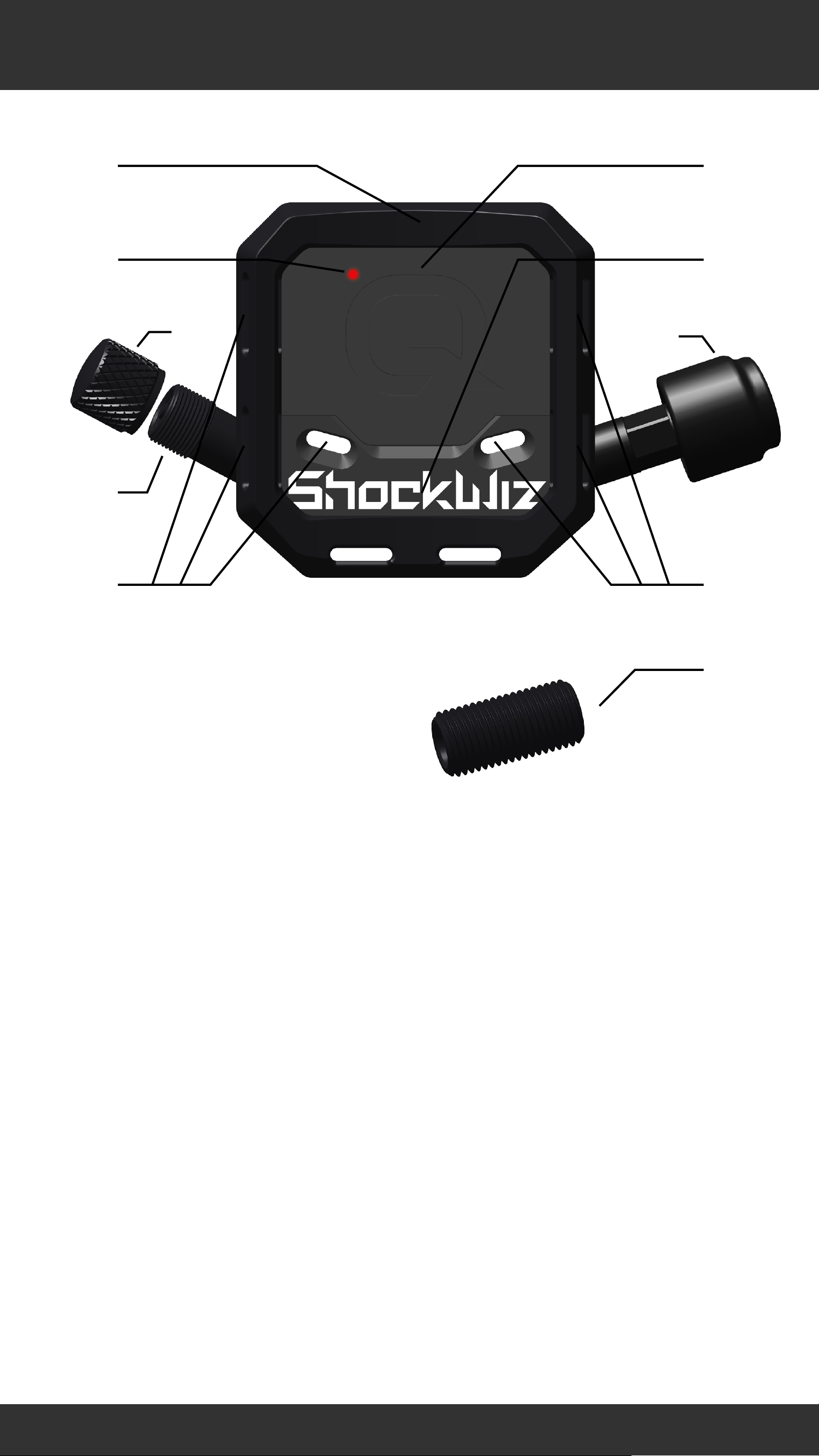
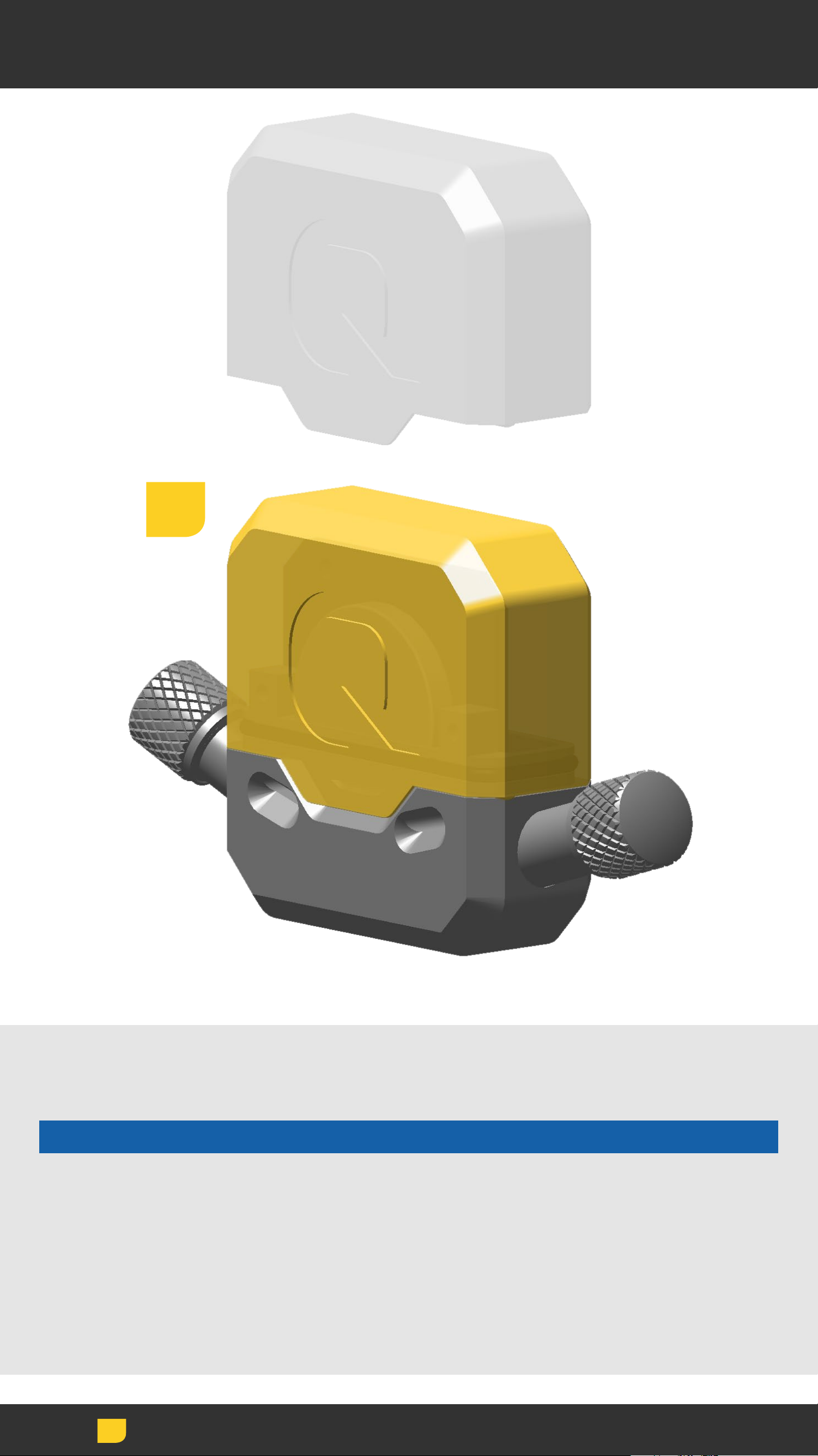
ShockWiz
a
b
c d
e
e
f
h
g
h
Mounting boot
b
c
d
e
f
g
h
Battery cover
LED status indicator
ShockWiz™ body
Air valve cap
Air inflation valve (L - 28°)
Air inflation valve (R - 17.5°)
Cable tie guide
5
5
Page 6
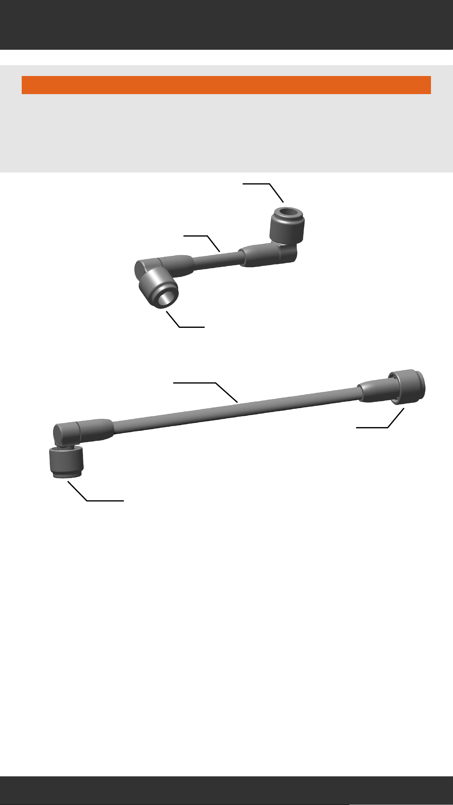
Hose Assembly
⚠WARNING
Do not use a hose assembly with inverted forks. Use
with a hose assembly on an inverted fork could cause a
crash resulting in serious injury to the rider.
a
d
b
a
b
c
a
Hose coupler (90°)
Short hose
c
d
Hose coupler (0°)
Long hose
6
6
Page 7
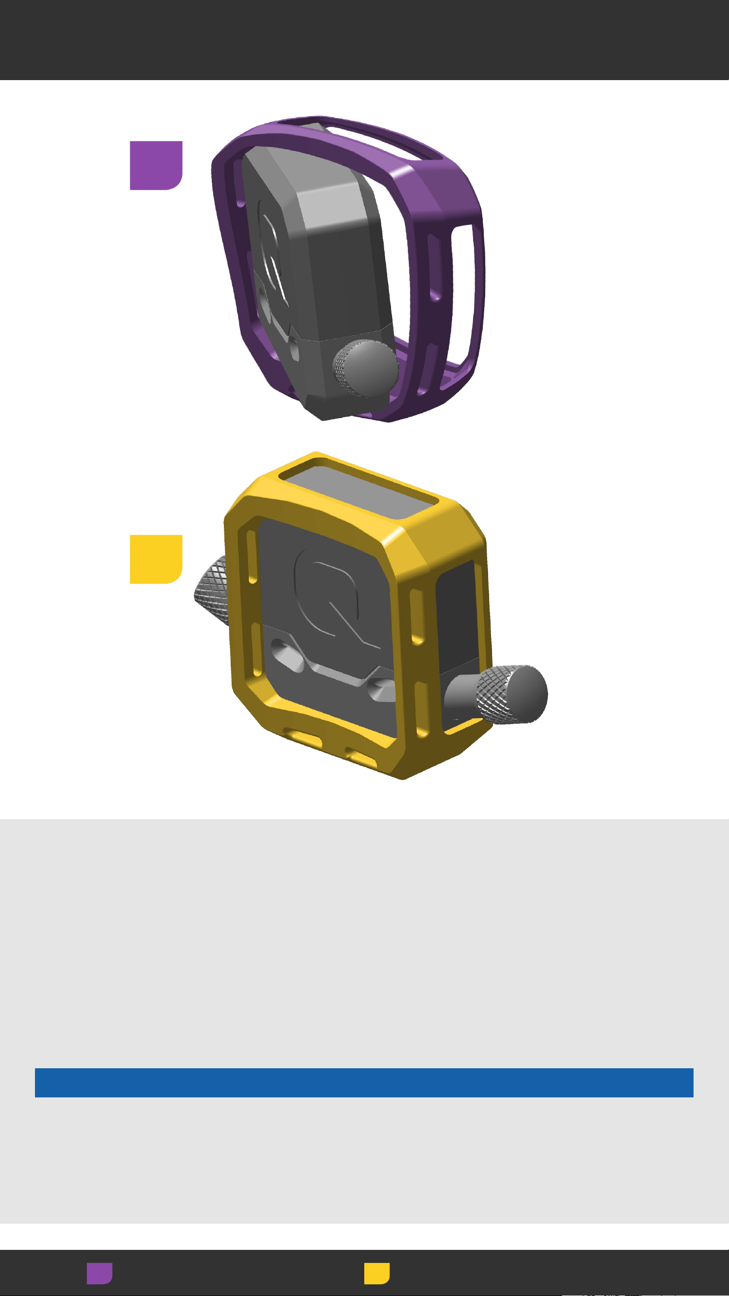
ShockWiz - Direct Mount
a
c
e
b
d
f
g
h
h
i
b
c
d
e
f
g
h
Mounting boot
Battery cover
LED status indicator
ShockWiz™ body
Air valve cap
Direct mount air valve coupler
Air inflation valve (L - 28°)
Cable tie guide
i
Direct Mount Hose Adapter
7
7
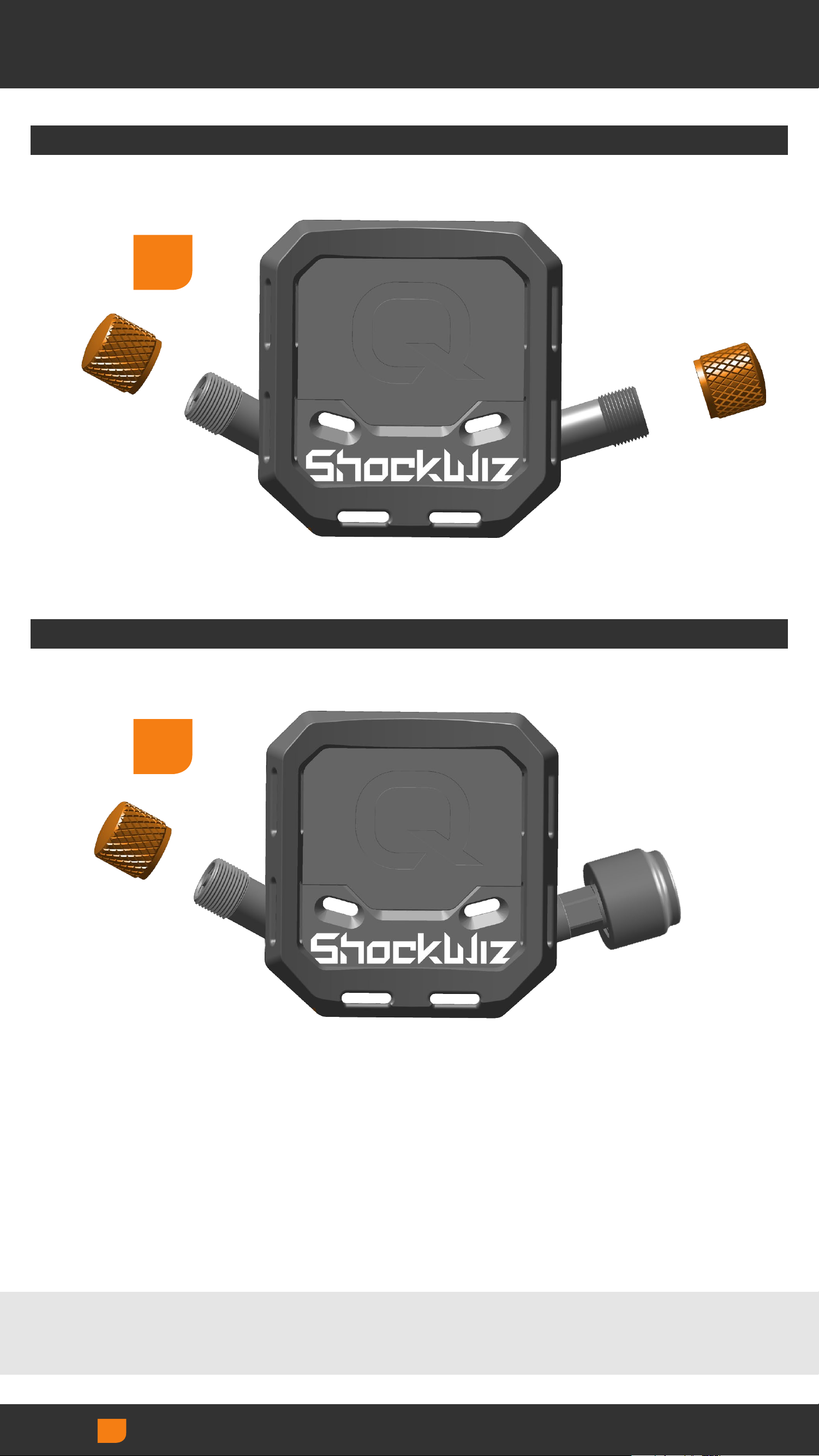
Page 8
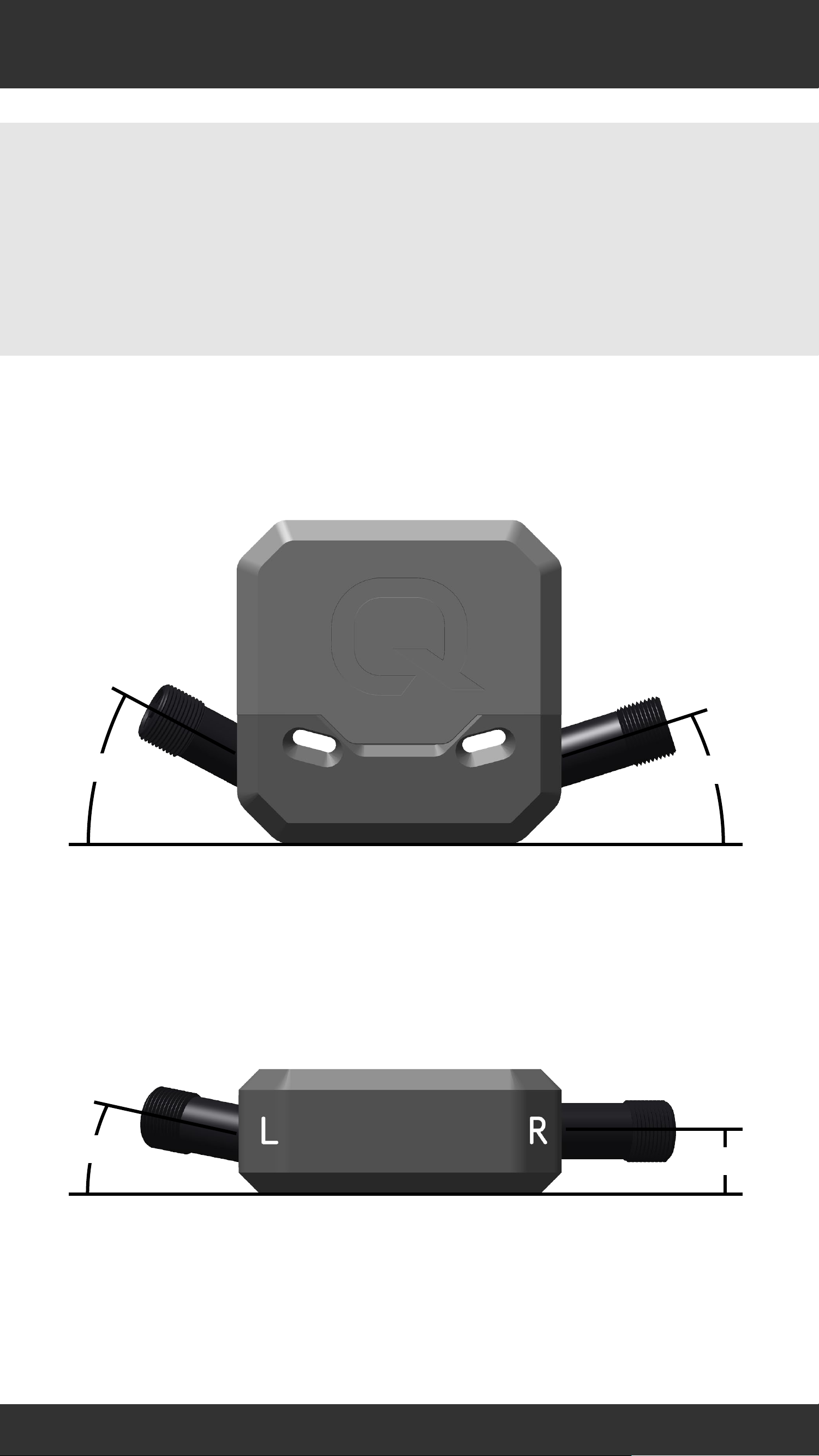
ShockWiz Air Valves
The ShockWiz™ air inflation valves are oriented at
differing angles for various mounting orientations.
Choose the optimal air valve angle for your suspension.
Test fit the position and orientation of ShockWiz before
installation.
28°
17.5°
10°
0°
8
8
Page 9

Battery
⚠WARNING
Do not use sharp or conductive
objects to remove the battery.
Keep the battery out of reach of
children.
Do not put the battery in your
mouth. If ingested, seek medical
attention immediately.
Do not disassemble, damage, or
puncture the battery.
Consult the battery manufacturer
for safe handling instructions.
9
9
Page 10
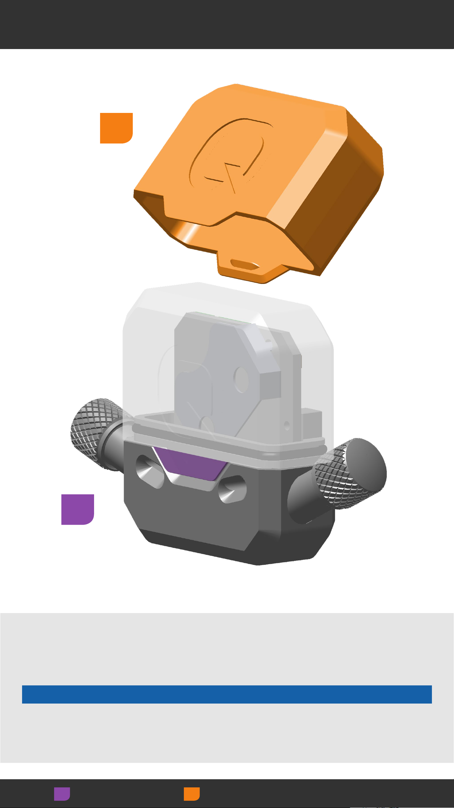
Remove Battery Cover
2
1
Gently lift one battery cover tab outward, then
the other, and remove the battery cover from the
ShockWiz™ body.
NOTICE
Do not use metal tools to pry the battery cover tab.
Metal tools may damage the cover.
Adjust Remove/Loosen
10
10
Page 11
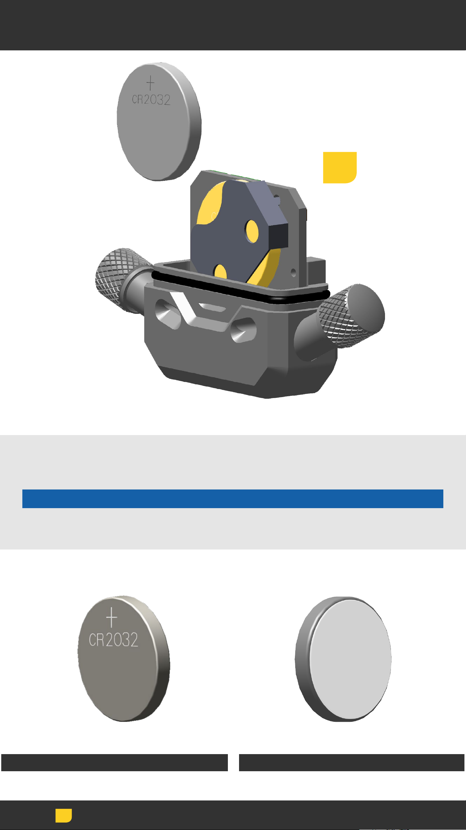
Install Battery
3
Insert a new CR2032 coin cell battery into the battery
slot, terminal side in, positive side (+) out.
NOTICE
Do not remove the battery with conductive objects.
Positive Side Terminal Side
Install
11
11
Page 12
Install Battery Cover
4
Install the battery cover onto the ShockWiz™ body. The
cover is secure when the each tab snaps flat into place.
NOTICE
Ensure the battery cover o-ring seal is clean and in the
groove around the ShockWiz body. Remove, clean, and
reinstall the o-ring if it is contaminated.
To avoid permanent damage caused by moisture, verify
the battery cover is securely attached before use.
Install
12
12
Page 13
Mounting Boot Installation
1
2
Install the rubber mounting boot onto ShockWiz™ in the
desired orientation.
The rubber mounting boot can be installed onto
ShockWiz in multiple orientations. Choose the
orientation that best fits your suspension. It may be
necessary to adjust the boot depending on suspension
mounting orientation.
NOTICE
Failure to install the included protective rubber
mounting boot onto ShockWiz may cause damage to
the fork and/or rear shock.
Adjust Install
13
13
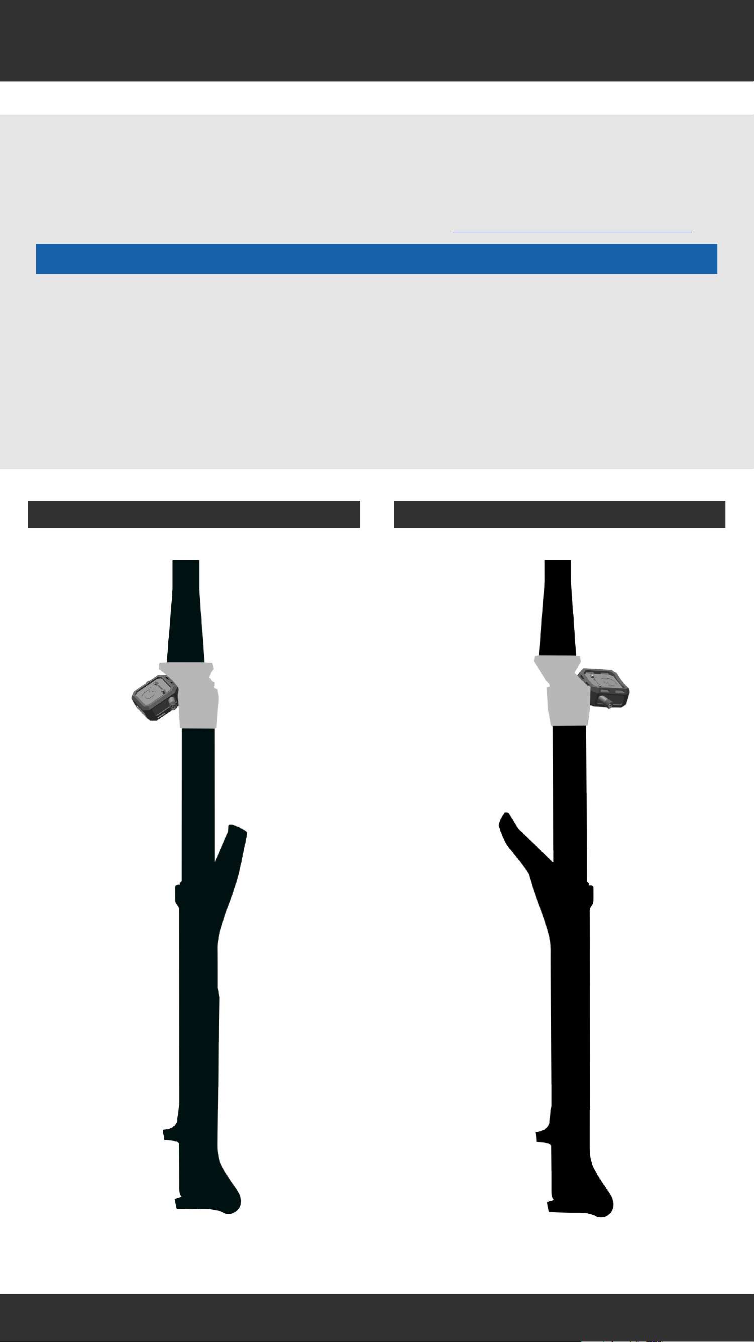
Page 14
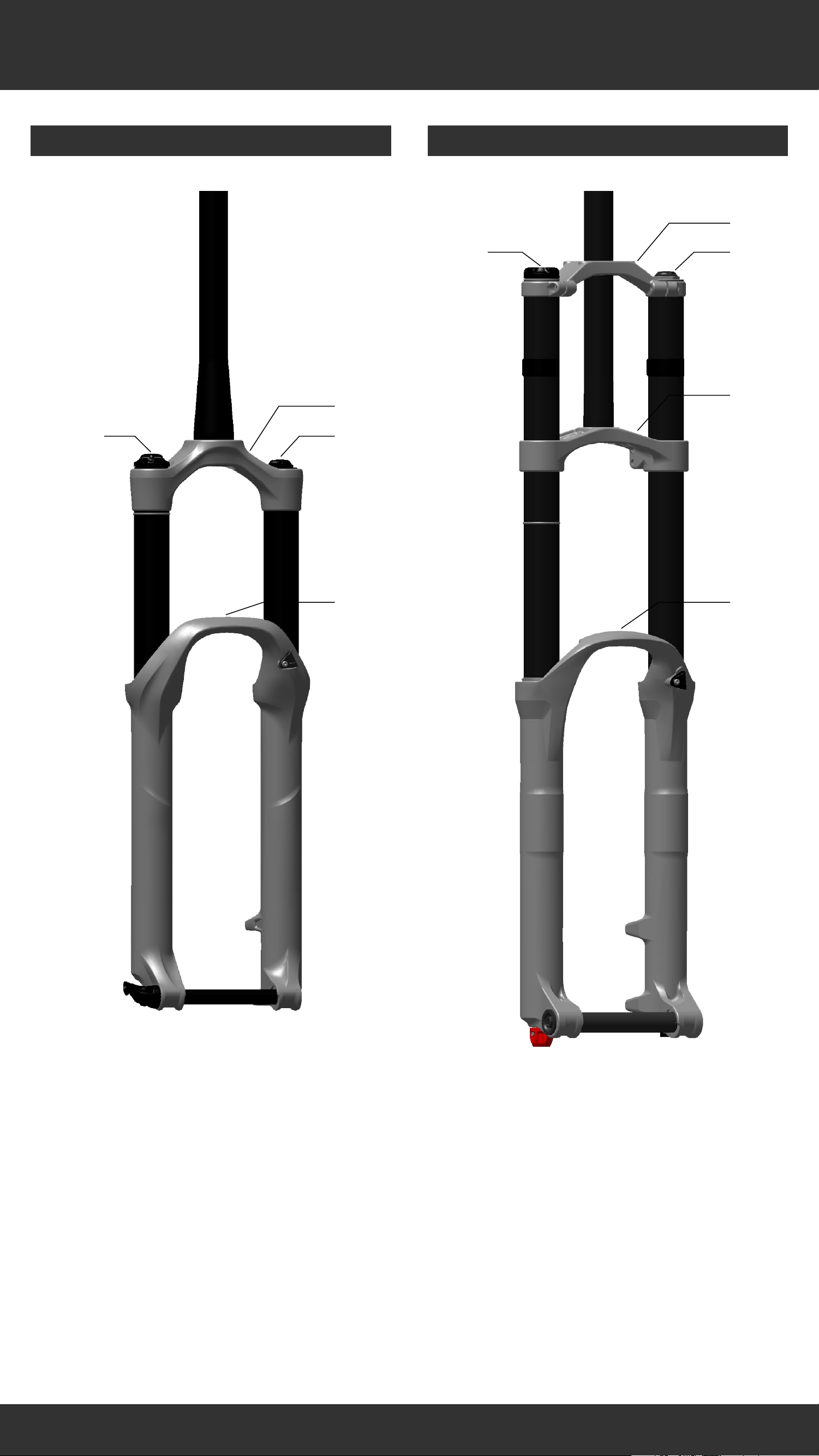
Front Suspension
Conventional Single Crown Conventional Dual Crown
a
b
a
c
b
c
d
d
e
b
c
d
Crown
Damper
Air spring inflation valve
Lower leg arch
b
c
d
e
Upper crown
Damper
Air spring inflation valve
Lower crown
Lower leg arch
14
14
Page 15
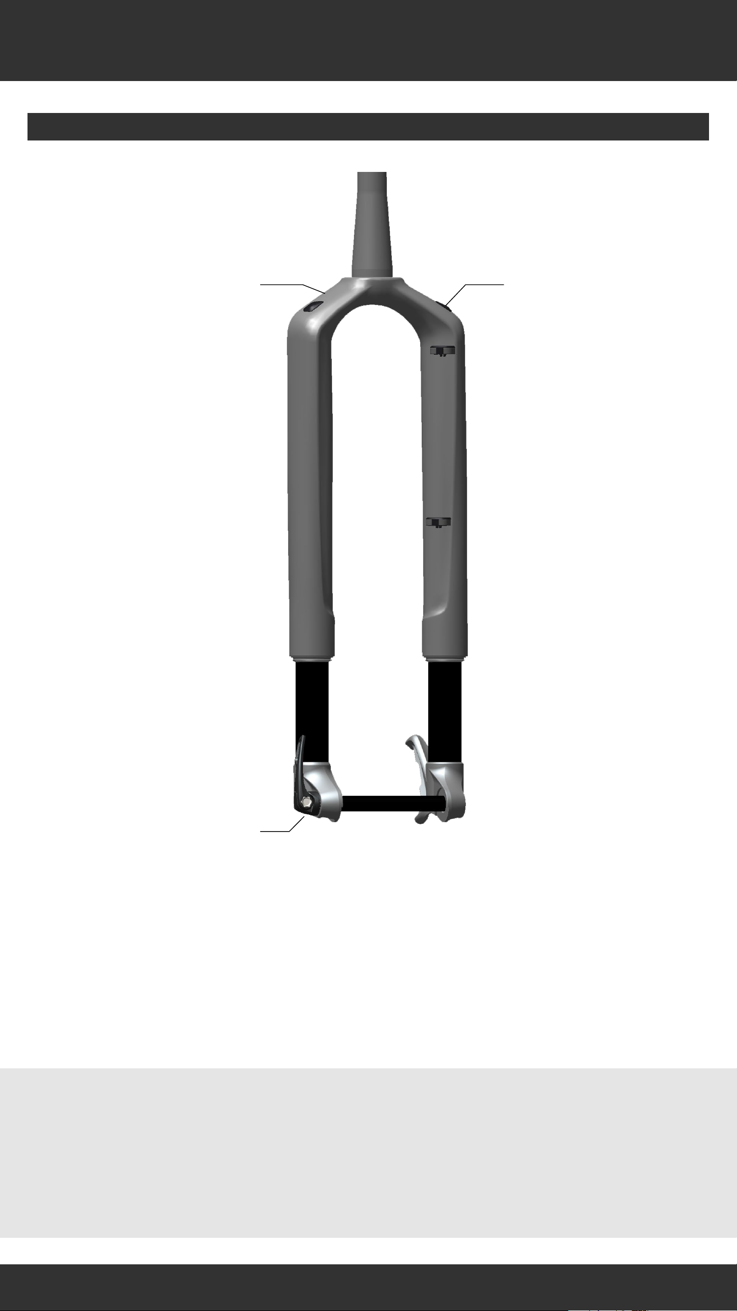
Front Suspension
Inverted
ba
c
b
c
Inverted fork designs vary. The air inflation
Upper Leg / Steerer Tube Assembly
Damper
Air spring inflation valve
valve may be on the drive or non-drive side.
Refer to the suspension manufacturer for more
information.
15
15
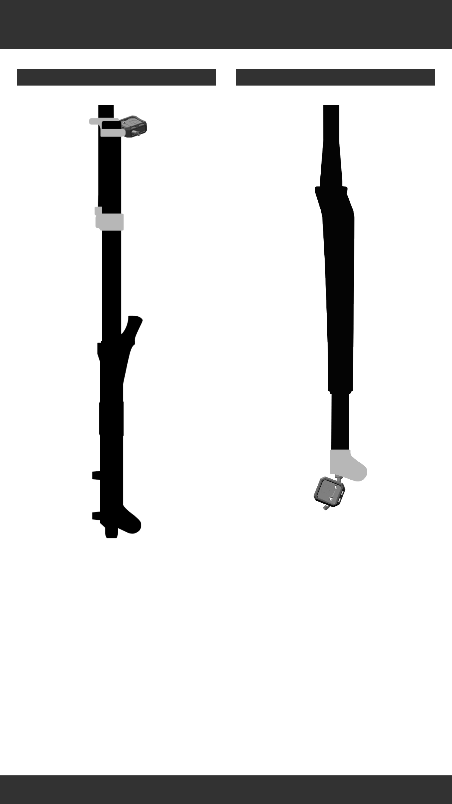
Page 16
Attachment Locations
ShockWiz™ is not compatible with all air suspension
forks.
For more information, please visit www.shockwiz.com.
NOTICE
Do not attach ShockWiz to any part of the fork that
moves independent of the air valve. ShockWiz must
not contact the fork upper tube or any part of the fork
that moves during compression. The hose cannot
move when the fork is compressed.
Crown Mount - Front Arch Crown Mount - Reverse Arch
16
16
Page 17
Attachment Locations
Direct Mount - InvertedCrown Mount - Dual Crown
17
17
Page 18
Remove Air Caps
Standard ShockWiz
1
1
Direct Mount ShockWiz
Remove the air valve cap(s).
Remove/Loosen
18
18
Page 19
Remove Air Caps
Crown Mount
2
Direct Mount (Inverted)
2
Remove the positive air inflation valve cap from the
fork.
To continue with Direct Mount installation, proceed to
Installation - Inverted.
Remove/Loosen
19
19
Page 20
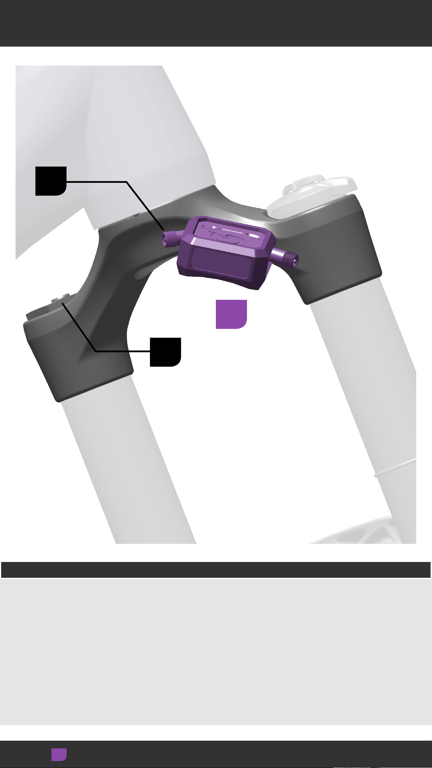
Crown Mount Location
A
B
3
Front and Reverse Arch
Front Arch Forks: Position ShockWiz™ on the back of
the fork crown, opposite the arch, on the damper side.
Reverse Arch Forks: Position ShockWiz on the front of
the fork crown, opposite the arch, on the damper side.
Orient the optimal ShockWiz air valve (A) toward the
fork air valve (B) for use with the long hose.
Adjust
20
20
Page 21
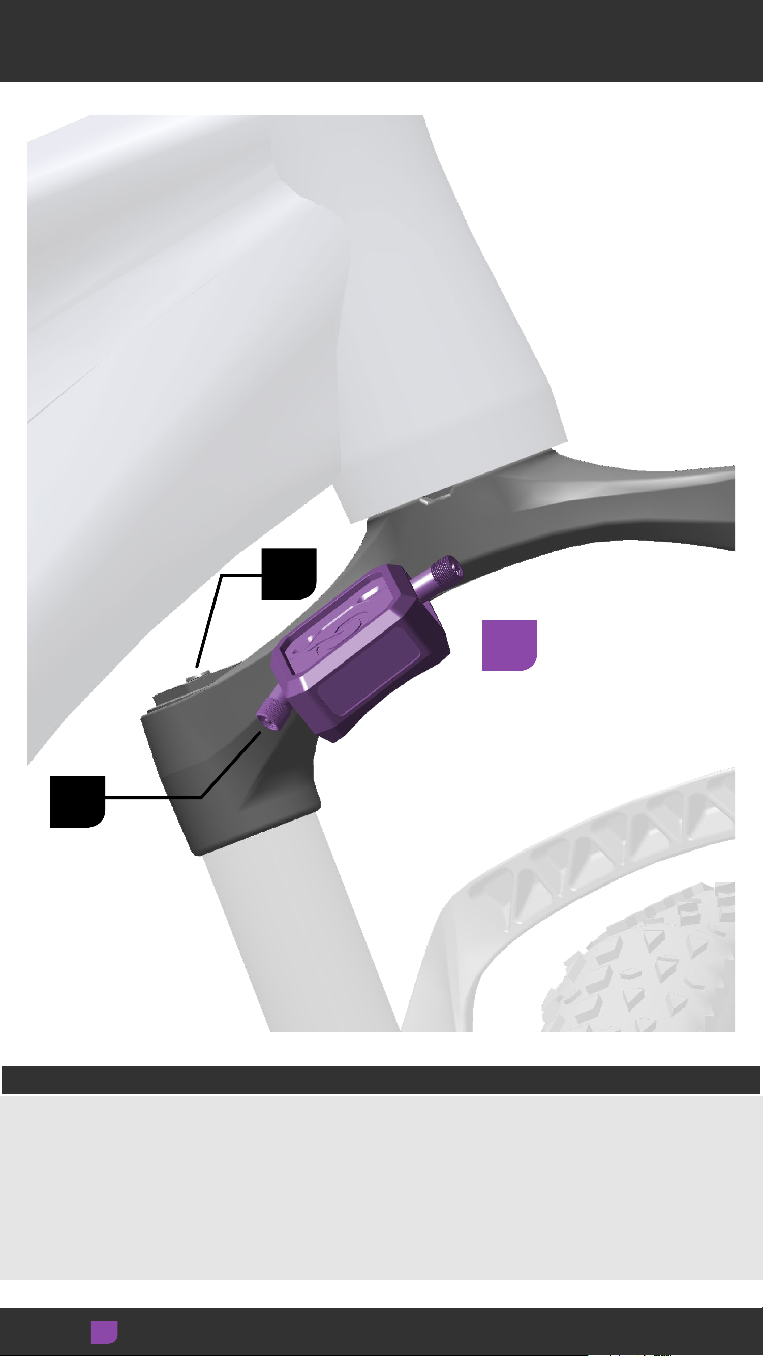
Crown Mount Location
A
B
3
Front Arch - Fat Bike
Position ShockWiz™ on the back of the fork crown,
opposite the arch, on the air inflation valve side.
Orient the optimal ShockWiz air valve (A) toward the
fork air valve (B) for use with the short hose.
Adjust
21
21
Page 22
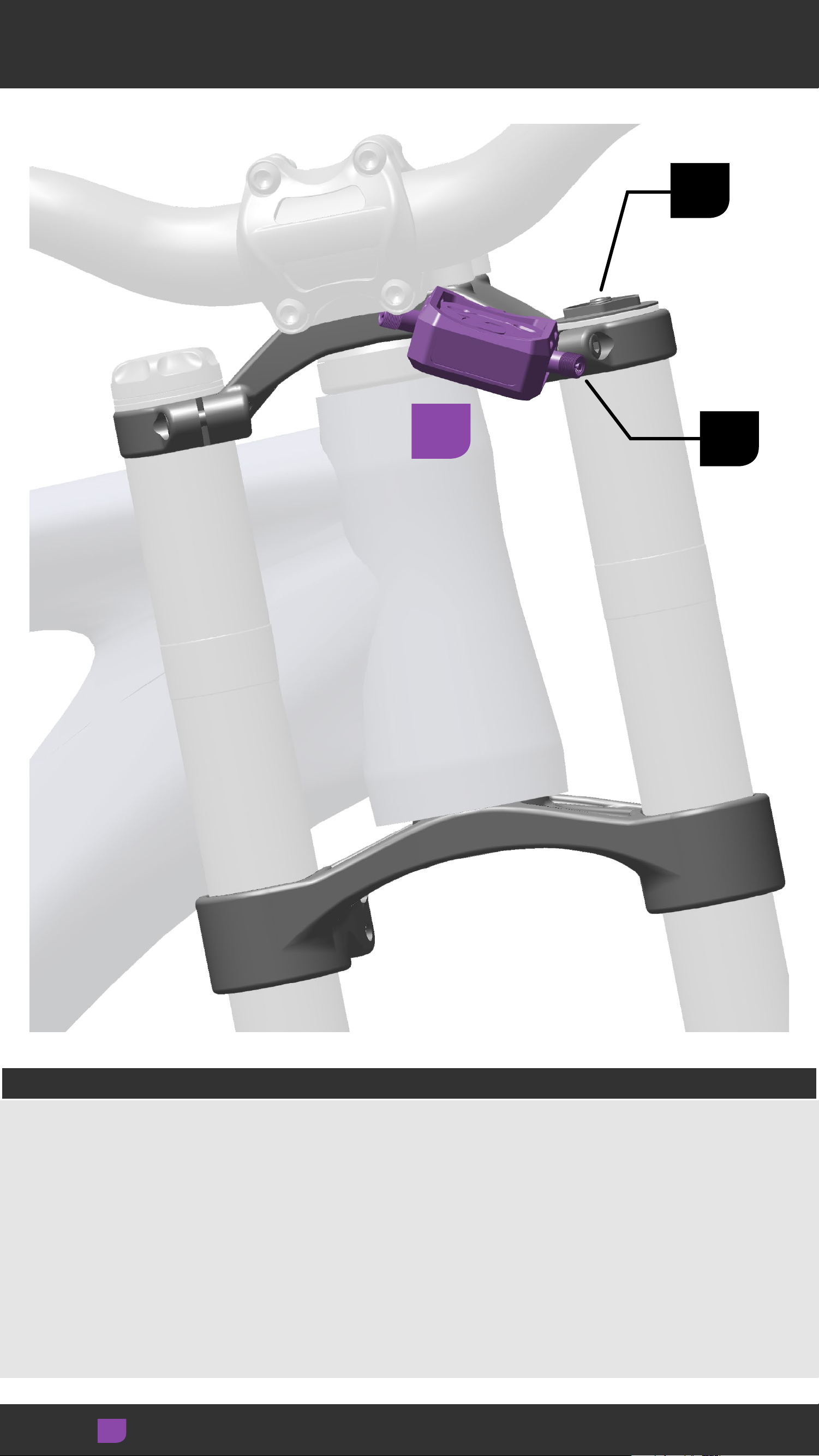
Crown Mount Location
B
3
A
Dual Crown
Position ShockWiz™ on the fork upper crown on either
the damper or spring side.
ShockWiz can be attached to any location and in any
orientation on the upper crown.
Orient the optimal ShockWiz air valve (A) toward the
fork air valve (B) for use with the short hose.
Adjust
22
22
Page 23
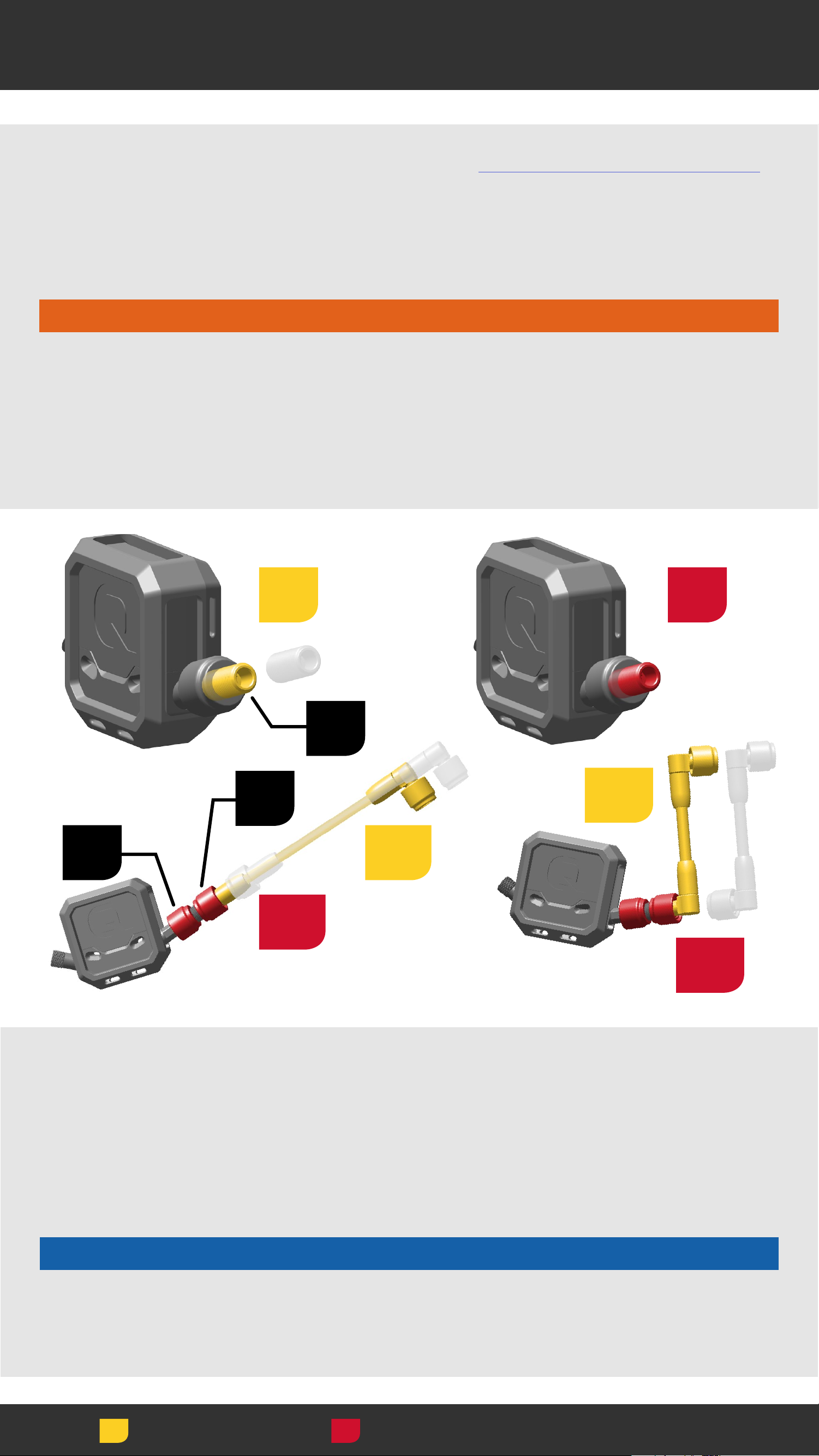
Hose Installation - Direct Mount
Standard ShockWiz: Proceed to ShockWiz Installation.
Install the Direct Mount Hose Adapter (A) when Direct
Mount ShockWiz™ is used with a ShockWiz hose on
conventional forks.
⚠WARNING
Use only Direct Mount ShockWiz without a hose on
inverted forks. Use of Direct Mount ShockWiz with a
hose on an inverted fork could cause a crash resulting
in serious injury to the rider.
1
2
B
C
4a
A
3b
3a
4b
Thread one end of the adapter (A) into the ShockWiz
Direct Mount coupler (B) and tighten hand tight.
Thread one hose coupler (C) onto the adapter and
tighten both couplers hand tight. Loose connections
will cause air to leak.
NOTICE
Do not use tools to tighten the hose coupler. Use of
tools can damage the coupler and air valve.
Install Torque
23
23
Page 24

ShockWiz Installation
4
Insert cable ties through the cable tie guide holes in
the ShockWiz™ body.
Install
24
24
Page 25

ShockWiz Installation
5
Affix ShockWiz™ tightly to the fork crown with the cable
ties. The device should not move.
Cut the excess ends of the cable ties.
Follow the same process for ShockWiz mounted to
the front or back of the fork crown.
Direct Mount: Hose installed (not pictured). Proceed to
Hose Installation - Fork.
Install
25
25
Page 26

Hose Installation - ShockWiz
6
7
Thread one end of the hose assembly onto the
ShockWiz™ air valve and tighten the hose coupler
hand tight.
Loose hose connections will cause air to leak.
Install the short hose assembly (90° coupler x2) on Fat
Bike and Dual Crown suspension forks.
*Compatible with short and long hose assemblies. Use
the appropriate hose length with your fork.
NOTICE
Do not use tools to tighten the hose coupler. Use of
tools can damage the coupler and air valve.
Install Torque
26
26
Page 27

Hose Installation - Fork
8
9
Thread the other hose coupler onto the fork air valve
and tighten the hose coupler hand tight.
Loose hose connections will cause air to leak.
NOTICE
Do not use tools to tighten the hose coupler. Use of
tools can damage the coupler and air valve.
Do not sharply bend or kink the ShockWiz™ hose. Sharp
bends or kinks will damage the hose.
Install Torque
27
27
Page 28

Check Clearance
⚠WARNING
ShockWiz™ must not contact the fork lower leg arch,
fork upper tubes, bicycle frame, tire, components, or
the rider during use. Contact while riding can cause
ShockWiz to disconnect from the fork and could cause
a crash resulting in serious injury to the rider.
1 3
2 4
Turn the handlebars to the left and right to confirm
ShockWiz and the hose assembly do not contact the
frame at any point during the full range of turning
motion.
If ShockWiz or the hose assembly contacts the frame,
adjust as needed.
Adjust
Measure
28
28
Page 29

Check Clearance
5
6
Single Crown Forks: Compress the fork to full bottom
out and confirm ShockWiz™ does not contact the tire or
fork lower leg.
If ShockWiz or the hose assembly contacts the frame,
tire, or lower leg adjust as needed.
29
Adjust
Measure
29
Page 30

Installation - Inverted Fork
⚠WARNING
Use only Direct Mount ShockWiz™ without a hose on
inverted forks. Use of Direct Mount ShockWiz with a
hose on an inverted fork could cause a crash resulting
in serious injury to the rider.
1 2
Thread the Direct Mount ShockWiz coupler onto the
fork air valve and tighten it hand tight.
Loose connections will cause air to leak.
NOTICE
Do not use tools to tighten the hose coupler. Use of
tools can damage the coupler and air valve.
Install Torque
30
30
Page 31

Check Clearance
2
1
Rotate and orient ShockWiz™ parallel with the wheel.
Confirm the coupler is tight and does not rotate during
use.
⚠WARNING
ShockWiz must not contact any part of the wheel.
Contact while riding can cause ShockWiz to disconnect
from the fork and could cause a crash resulting in
serious injury to the rider.
Adjust Measure
31
31
Page 32

Rear Suspension
Standard Reservoir
a
b
a
b
c
c
d
b
c
Air spring inflation valve
Air Can
Shock damper body
b
c
d
Air spring inflation valve
Reservoir
Air Can
Shock damper body
32
32
Page 33

Attachment Locations
ShockWiz™ is not compatible with all air sprung rear
shocks. For more information, please visit
www.shockwiz.com.
Attach ShockWiz to the rear shock air can nearest to
the fixed air inflation valve.
NOTICE
Do not attach ShockWiz to any part of the shock that
moves independent of the air valve. ShockWiz must
not contact the shock body or any part of the shock
that moves during compression. The hose cannot
move when the shock is compressed.
Reservoir on
No Reservoir
Air Can
Reservoir on
Damper Body
33
33
Page 34

Remove Air Caps
Standard ShockWiz
1
1
Direct Mount ShockWiz
Remove the air valve cap(s).
Remove/Loosen
34
34
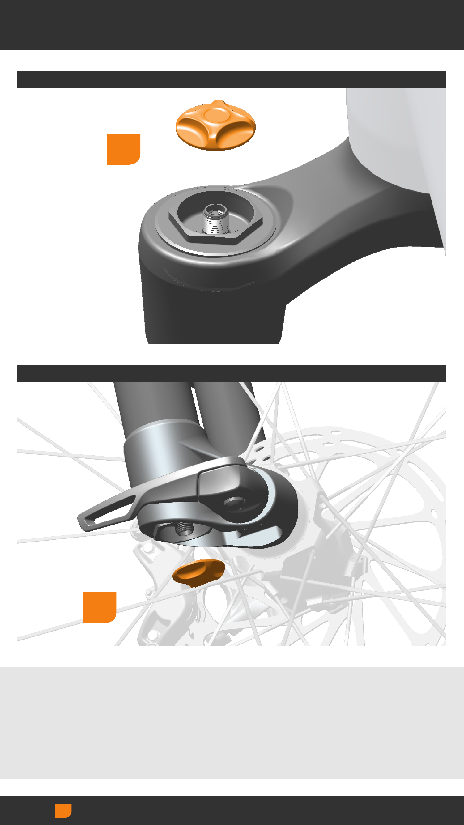
Page 35

Remove Air Cap
2
1 1
Remove the positive air spring inflation valve cap from
the rear shock.
NOTICE
Reservoir Rear Shocks: Do not remove the air valve
cap from the shock reservoir. ShockWiz™ does not
connect to the shock reservoir air valve.
Remove/Loosen
35
35
Page 36

Attachment Location
C
A
3
B
Position ShockWiz™ on the rear shock air can close
enough to the rear shock air inflation valve to connect
the hose.
Orient the curved side (A) of the rubber mounting boot
against the air can.
Orient the optimal ShockWiz air inflation valve (B)
toward the shock air inflation valve (C).
36
Adjust
36
Page 37

Hose Installation - Direct Mount
Standard ShockWiz: Proceed to ShockWiz Installation.
Install the Direct Mount Hose Adapter when Direct
Mount ShockWiz™ is used with a ShockWiz hose.
1
2
A
3
B
C
4
Thread one end of the adapter (A) into the Direct
Mount coupler (B) and tighten hand tight.
Thread the hose coupler (C) onto the adapter and
tighten both couplers hand tight.
Loose connections will cause air to leak.
NOTICE
Do not use tools to tighten the hose coupler. Use of
tools can damage the coupler and air valve.
Install Torque
37
37
Page 38

ShockWiz Installation
4
5
Insert plastic cable ties through the guide holes on
the curved side of the rubber mounting boot and affix
ShockWiz™ tightly to the rear shock air can.
Cut the excess ends of the cable ties.
Direct Mount: Hose installed (not pictured). Proceed to
Hose Installation - Shock.
38
Install
38
Page 39

Hose Installation - ShockWiz
7
6
Thread one end of the short hose assembly onto the
ShockWiz™ air valve. Tighten the hose coupler hand
tight.
Loose hose connections will cause air to leak.
NOTICE
Do not use tools to tighten the hose couplers. Use of
tools can damage the coupler and air valve.
39
Install Torque
39
Page 40

Hose Installation - Shock
9
8
Thread the other end of the hose assembly onto the
rear shock air inflation valve. Tighten the hose coupler
hand tight.
Loose hose connections will cause air to leak.
NOTICE
Do not use tools to tighten the hose coupler. Use of
tools can damage the coupler and air valve.
Do not sharply bend or kink the ShockWiz™ hose. Sharp
bends or kinks will damage the hose.
Install Torque
40
40
Page 41

Check Clearance
⚠WARNING
ShockWiz™ must not contact the shock damper body,
shock reservoir, bicycle frame, tire, components, or
the rider during use. Contact while riding can cause
ShockWiz to disconnect from the shock and could
cause a crash resulting in serious injury to the rider.
1
2
Fully compress the shock, rotate the crank backward,
and confirm ShockWiz does not contact the frame,
crank arm, components, or the rider.
If ShockWiz, or the hose assembly make contact, adjust
as needed before use.
41
Adjust
Measure
41
Page 42

ShockWiz App Set Up
ShockWiz™ must be on to connect to the app.
ShockWiz is motion-activated. Bounce the wheel to
turn ShockWiz on.
A flashing LED on one side of the device will indicate
ShockWiz is on.
ShockWiz will turn off automatically when idle for
10 minutes.
42
42
Page 43

Connect to App
Open the ShockWiz™ App.
43
43
Page 44

Connect to App
From the Home screen, select Connect.
Bluetooth® must be activated on your smartphone
or tablet.
Adjust
44
44
Page 45

Connect to App
Select your ShockWiz™.
For first time use the device name will appear as:
ShockWiz_Serial Number.
The serial number is printed on the ShockWiz device.
Adjust
45
45
Page 46

Connect to App
When ShockWiz™ is connected with the app, the Home
screen will display information from the device.
Air Pressure and Shock Travel readings may fluctuate
slightly when the bike is idle. This is normal.
46
Adjust
46
Page 47

Rename Device
To rename the device, select the connected ShockWiz™
device in green.
47
Adjust
47
Page 48

Rename Device
Select Rename.
Adjust
48
48
Page 49

Rename Device
Select the device name to activate the entry bar.
Enter the new device name.
Select OK to save.
Adjust
49
49
Page 50

Rename Device
Select Close to exit.
Adjust
50
50
Page 51

Rename Device
The new ShockWiz™ name will be visible in the Home
screen in green.
To rename the device again follow the same
procedures.
51
51
Page 52

Pressure Unit and Altitude
Select Air Pressure.
Adjust
52
52
Page 53

Select Unit and Altitude
Select Pressure Units.
Select Reference Altitude, then select Done.
Select Info for Altitude range details.
Adjust
53
53
Page 54

Calibration Wizard
ShockWiz™ must be calibrated with the suspension fork
or rear shock before use. The Calibration Wizard will
guide you through the Calibration process.
ShockWiz must be installed onto the suspension fork or
rear shock during calibration.
In the Settings screen, select Calibration Wizard.
Adjust
54
54
Page 55

Calibration Wizard
Select Begin and complete the Calibration process.
Repeat the entire process if a second ShockWiz™
is installed.
Adjust
55
55
Page 56

Calibration Wizard
When complete, take a screenshot of your
Compression Ratio and Baseline Air Pressure for
future reference.
Shock Travel displayed should read 0%.
If Shock Travel displayed exceeds ±3%, an error
was made during calibration. The Mark Baseline Air
Pressure process must be repeated. Go to Settings
and repeat the Mark Baseline Air Pressure procedure.
Shock Travel readings may fluctuate slightly when the
bike is idle. This is normal.
56
56
Page 57

Select Tuning Style
ShockWiz™ offers four Tuning Styles that allow you to
customize the ride and feel of your bike.
Select Tuning Style.
Balanced is the default setting.
Adjust
57
57
Page 58

Select Tuning Style
Select your preferred Tuning Style.
This can be changed at any time and will not erase
ride data.
Select Info for Tuning Style details.
Adjust
58
58
Page 59

Select Tuning Style
The selected Tuning Style will be displayed on the
Home screen.
ShockWiz™ is now ready to analyze your suspenion.
59
59
Page 60

Ride Session
ShockWiz™ records your suspension's performance
during the ride Session. ShockWiz wirelessly transfers
data to the ShockWiz App when your connected
smartphone or tablet is in close proximity to the
ShockWiz device.
ShockWiz must be 'on' for data to transfer to the app.
Bounce the front wheel to turn ShockWiz on, and
Connect to the app, if idle for more than 10 minutes.
When a ride Session is complete, you will review
performance in the app and make adjustments to the
suspension as recommended.
ShockWiz does not have to be connected to the
ShockWiz app while riding. All data collection and
analysis is performed within the ShockWiz device and
uploads to the app when connected. Results can be
viewed in the app at any time. ShockWiz saves ride
data until a new Session is started.
IMPORTANT
While tuning with ShockWiz, any time a damping
adjustment is made to your suspension, you must
select Start New Session to clear all existing ride data.
Any time air spring pressure is changed, you must
reset Baseline Air Pressure in the Settings screen.
Any time Air Spring Ramp is changed, you must
remeasure the Compression Ratio in the Calibration
Wizard.
Refer to the suspension manufacturer for adjustments
available on your suspension.
60
60
Page 61

Riding with ShockWiz
ShockWiz™ must record particular suspension
movements during a ride Session.
ShockWiz converts measured suspension pressure into
Shock Travel percentage by using the Compression
Ration and Baseline Air Pressure established during
the Calibration procedure.
By monitoring suspension movement, ShockWiz builds
a set of Detections to analyze performance. When
the number of Detections are sufficient, ShockWiz
can determine which suspension Settings should be
adjusted to improve performance.
For effective results, follow these ride Session
recommendations:
1. Ride a variety of terrain including the following:
• Rocky, rolling, and flat terrain
• Climbing and descending
• Jumps and drops
• Sucessive small, medium, and large bumps
• Low and high speed bumps
2. Do not make air pressure or damper changes to the
suspension during the ride Session.
If changes to air pressure and/or damper settings
are made, a new Session must be started prior to
further riding.
When Start New Session is selected,
ShockWiz resets the Detections recorded in the
prior Session.
3. Do not lock the suspension out, and do not adjust
threshold, or pedal platform, during the Session.
61
61
Page 62

Start New Session
It's time to start a new Session and go for a ride!
Select Start New Session and go for a ride so
ShockWiz™ can collect data to analyze.
Selecting Start New Session resets the ShockWiz data
set and clears Suggestions and Detections.
62
Adjust
62
Page 63

Shock Tuning Score
When the ride Session is over, open the app and check
your Shock Tuning Score and Confidence.
If you are using more than one ShockWiz™, you must
connect the app to each separately.
63
63
Page 64

Shock Tuning Score
Shock Tuning Score is a value placed on your current
suspension performance during the ride Session.
To improve the Shock Tuning Score, select Detections
to review suspension behaviors, and Suggestions
to review recommended suspension adjustments to
improve negative suspension behavoirs.
64
Adjust
64
Page 65

Confidence
Confidence indicates the percentage of sufficient
data collected that ShockWiz™ needs to provide an
effective Shock Tuning Score and tuning Suggestions.
Suspension tuning adjustments are not recommended
unless Confidence reads greater than 50%.
If Confidence reads less than 50%, refer to What To
Ride Next.
65
65
Page 66

What To Ride Next
To increase Confidence percentage, ride the
suggested terrain in What To Ride Next so ShockWiz™
can collect the additional ride Detections required.
66
66
Page 67

Suggestions
Review Suggestions when the Confidence score
exceeds 50%.
Adjustments are not recommended if a green bar
is visible at OK. Adjustments are recommended if
a yellow (small change) or red (large change) bar is
visible.
If 'Not enough data' is indicated, ShockWiz™ was
unable to collect enough data during the Session to
make a Suggestion.
Select any Suggestion for more information.
Adjust
67
67
Page 68

Suggestions
Make each suggested adjustment, as is available, to
your suspension in the order listed in Suggestions.
Move on to the next adjustment when the previous
Suggestion indicates 'OK' after each ride Session.
If Air Spring Ramp is adjusted, you must complete the
Calibration process again.
If Air Spring Ramp is not adjusted, Baseline Air
Pressure can be adjusted individually.
Adjust Rebound damping next, followed by High
Speed Compression and Low Speed Compression.
Repeat the entire process for each suspension
component until you are satisfied with the Shock
Tuning Score and ride quality.
IMPORTANT
While tuning with ShockWiz™, any time an adjustment
is made to the suspension component, you must
start a new Session within the app before riding and
collecting new data.
Reference the unique notice found at the top of each
Suggestion's information page for instruction on what
to do after adjustments to that setting are made.
Go to www.shockwiz.com for more tuning information.
68
68
Page 69

Detections
To further review how Suggestions have been
determined, go to Detections to review a rating of
undersirable suspension characteristics.
When sufficient data is collected, a Suggestion, or
suspension adjustment, is made to improve that
negative performance behavior.
If ShockWiz™ did not collect enough data during a
Session for a particular Detection, 'Not enough data'
will be reported. More ride data is needed for that
particular Detection.
Select any Detection for more information.
Refer to What To Ride Next as an indicator of why a
Detection may read 'Not enough data'.
Adjust
69
69
Page 70

Statisitcs
Statistics displays additional ride metrics captured
during the ride Session.
Select any Statistic for additional information.
Adjust
70
70
Page 71

Removal
A A
B
(A) Unthread the hose coupler from the fork or shock
air valve.
The hose coupler must be removed from the fork or
shock first to avoid suspension air pressure loss.
Cut the cable ties and remove ShockWiz from the fork
or shock.
Install the fork or rear shock air cap.
(B) Unthread the air valve coupler from the fork.
Install the fork air cap.
Remove/Loosen
71
71
Page 72

Maintenance
Clean ShockWiz™ after use.
Remove the rubber mounting boot and use a damp
cloth to wipe off dirt and debris.
NOTICE
Do not use a pressure washer to clean.
Do not use acidic or grease dissolving agents.
Chemical cleaners and solvents can cause permanent
damage to the electronics.
72
72
Page 73

iOS® is a registered trademark of
Cisco Technology, Inc.
Android® is a registered trademark
of Google Inc.
The Bluetooth® word mark and
logos are registered trademarks
owned by the Bluetooth SIG, Inc.
and any use of such Marks by
SRAM® is under license. Other
trademarks and trade names are
those of their respective owners.
73
73
Page 74

www.sram.com
74
74
 Loading...