

Page 1

DualDrive · December 2002
1
E
D
F
Nl
Dk
Sv
user manual
betriebsanleitung
notice d’utilisation
handleiding
brugsanvisning
bruksanvisning
Page 2

i-MOTION 3 · June 2006
2
Precautionary measures,
which protect from possible
accident, injury or danger to
life, or which prevent possible
damage to the bicycle.
These instructions contain
important information about your
SRAM i-MOTION 3 System.
Please take the time to read these
operating instructions carefully.
Your SRAM i-MOTION 3 System is
almost maintenance-free. Should
you have any queries that are
not answered in these operating
instructions, your qualified bicycle
specialist will be pleased to help
you.
Have a nice time and enjoy your
SRAM i-MOTION 3.
Special advice to assist in the
better handling of the operation, control, and adjustment
procedures.
Please note:
© Copyright SRAM Corporation 2006
Publ. No. 5300 E/D/F/Nl/Dk/Sv
Information may be enhanced
without prior notice.
Released June 2006
SRAM Technical Documentation,
Schweinfurt/Germany
Page 3

i-MOTION 3 · June 2006
3
E
THE SRAM i-MOTION 3 SYSTEM
4
OPERATION
5
MAINTENANCE AND CARE
» Gear adjustment 6
» Remove and fit rear wheel 7
» Cleaning and lubrication 10
» Repair work / wear parts 11
ASSEMBLY OF COMPONENTS
12
TECHNICAL DATA
18
TABLE OF CONTENTS
Page 4

i-MOTION 3 · June 2006
4
A modern bicycle derailleur should
be sporty, load shiftable, intuitive
to use and durable! With the new
i-MOTION 3, SRAM delivers an
internal gear hub that meets and
exceeds all these requirements!
i-MOTION 3 shifter
Intuitive gear indication, highquality design.
i-MOTION 3 gear hub
Load shiftable. Light shifting
forces. Shifting during standstill is possible: Easy re-start
e.g. at a traffic light.
i-MOTION 3 connecting link
Easy wheel removal:
The gear adjustment remains
unchanged.
THE SRAM i-MOTION 3 SYSTEM
Page 5

i-MOTION 3 · June 2006
5
E
OPERATION
SHIFTING
1
Shift gears by turning the
rotating grip.
» You can shift while standing still
or while riding your bicycle.
» When approaching inclines shift
down in good time.
» The smoothest and fastest gear
change happens when changing
gears while pedaling with low
force.
BRAKING
On long and steep downhill roads,
simultaneously use rear and front
brakes to avoid heating up of the
brakes.
Excessive heating of the hub
with the back pedal brake
may result in loss of lubricant and
braking too hard. This will lead to a
trip to the repair shop.
Read the applicable user
manual for each bicycle
equipped with i-BRAKE or band
brakes.
1
Page 6

i-MOTION 3 · June 2006
6
MAINTENANCE AND CARE
GEAR ADJUSTMENT
2
Shift the twist shifter to the
3rd gear.
The shift cable must be with-
out play in 3rd gear. That
means it must be pulled out of the
hub as far as it will go.
3
While pulling the plastic re-
tainer (1), it should not be possible to pull the shift cable further
out of the hub.
– Shift cable has too much play:
Shift the twist shifter to the 1st
gear.
4
Reduce play of the shift
cable by turning the barrel
adjuster (2) at the shifter.
– Shift cable is too taut:
The shifter won‘t shift into 3rd
gear or the hub doesn‘t shift in
1st gear or will permanently
switch between 1st and 2nd
gear.
Shift the twist shifter to the 1st
gear.
4
Decrease shift cable tension by turning the barrel
adjuster (2) at the shifter.
» Shift the twist shifter to the 3rd
gear and check again, until there
isn‘t any play in the shift cable.
2
4
2
1
3
Page 7
i-MOTION 3 · June 2006
7
E
5
MAINTENANCE AND CARE
REMOVE AND FIT REAR WHEEL
REMOVING THE REAR
WHEEL
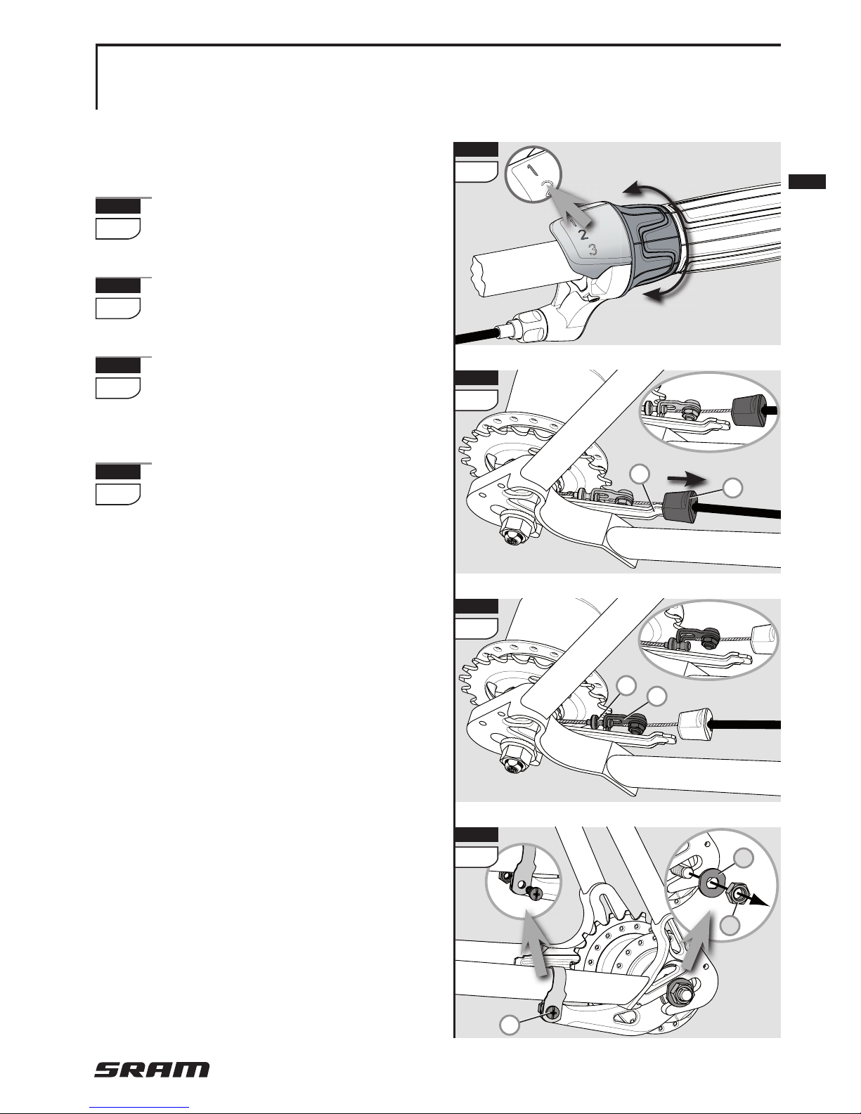
5
Shift the twist shifter to the 1st
gear.
6
Pull the plastic retainer (1) off
the cable stop bracket (2).
7
Disconnect the shift cable by
disengaging the link (3) of the
cable nipple (4).
8
Loosen the axle nuts (5) and
remove the nuts and the retaining washers (6) underneath
them.
If applicable, unscrew the frame
clamp connection (7) of the brake
lever.
» Remove the rear wheel.
1
2
6
3
4
7
8
7
5
6
Page 8

i-MOTION 3 · June 2006
8
FITTING THE REAR
WHEEL
» Place the rear wheel into the rear
frame.
9
Slide one retaining washer
each (1) onto each axle end.
The serrations of the retaining
washer must bear against the
dropout of the frame.
10
Align the cable stop bracket (2)
parallel to the frame stay (3).
11
Mount the axle nuts (4) and
tighten them alternately with
a torque of 30 – 40 Nm (266 – 350
in.lbs.).
12
If applicable, mount the brake
lever (5) between the two
straps of the frame clamp (6).
The frame clamp must be
seated on the frame with no
play. Use only self-locking nuts!
Tightening torque: 2 – 3 Nm (18 –
27 in.lbs.).
MAINTENANCE AND CARE
REMOVE AND FIT REAR WHEEL
1
9
4
11
5
6
12
2
10
3
Page 9

i-MOTION 3 · June 2006
9
E
13
13
Make sure that the shifter is
set to the 1st gear.
14
Make the cable connection by
hooking in the link (7) of the
shift cable to the cable nipple (8)
on the hub.
15
Slide the plastic retainer (9)
completely onto the cable stop
bracket (10).
MAINTENANCE AND CARE
REMOVE AND FIT REAR WHEEL
7
8
14
9
10
15
Page 10

i-MOTION 3 · June 2006
10
CLEANING
» Your SRAM i-MOTION 3 compo-
nents are well protected from
external evironmental impacts.
However, do not use water under
pressure (such as pressure washers or water jets) for cleaning to
prevent malfunctions due to water
penetration.
» During the winter season, you
should clean your bicycle in
shorter intervals so that winter
road salt cannot cause any dam-
age.
» Do not use agressive cleaners.
» Clean dirty chains before oiling.
Let cleaner set for only a few
minutes and rinse with water. Do
not oil chain until completely dry.
LUBRICATION
» The rear wheel hub is provided
with permanent lubrication and
maintenance-free under normal
conditions.
» Regular lubrication will extend the
chain's service life.
MAINTENANCE AND CARE
CLEANING AND LUBRICATION
Page 11

i-MOTION 3 · June 2006
11
E
REPAIR WORK
Only a qualified bike dealer
should perform any necessary
work on the gear hub, shifter, and
brakes.
» Unauthorized work on your
i-MOTION 3 system could endanger you and your warranty may
become void.
» Please contact your qualified bike
dealer regarding any questions or
problem you may have.
Back pedal brake
If the back pedal brake is braking
too hard, the brake jacket has to be
lubricated with special grease. This
work must be performed by a qualified bike dealer.
Cable Change
If a cable must be replaced (shifter
cable or brake cable), contact your
qualified dealer.
WEAR PARTS
Brake liners or brake jackets, brake
cables, shift cables, handlebar
grips, sprockets, and bike chains
are wear parts. Please check these
parts regularly and replace them
timely.
MAINTENANCE AND CARE
REPAIR WORK / WEAR PARTS
Page 12

i-MOTION 3 · June 2006
12
ASSEMBLY HUB
» Spoke the hub as normal.
16
Set the dust cover (1) onto the
driver. The curve must point to
the outside.
17
Set the sprocket (2) onto the
driver.
If an offset sprocket will be used,
mount the sprocket with the curve
pointing to the outside.
18
Mount the sprocket retaining
ring (3) onto the driver. Check
proper seat of the retaining ring.
19
Slide the cable stop bracket (4)
onto the axle end of the
sprocket side. Thereafter mount
the washer with rubber insert (5)
to fix the the cable stop bracket.
» Place the rear wheel into the rear
frame.
ASSEMBLY
OF COMPONENTS
3
1
2
18
17
16
19
4
5
Page 13

i-MOTION 3 · June 2006
13
E
20
Slide one retaining washer
each (6) onto each axle end.
The serrations of the retaining
washer must bear against the
dropout of the frame.
21
Align the cable stop bracket (7)
parallel to the frame stay (8).
22
Mount the axle nuts (9) and
tighten them alternately with
a torque of 30 – 40 Nm (266 – 350
in.lbs.).
23
If applicable, mount the brake
lever (10) between the two
straps of the frame clamp (11).
The frame clamp must be
seated on the frame without
play. Use only self-locking nuts!
Tightening torque: 2 – 3 Nm (18 –
27 in.lbs.).
ASSEMBLY
OF COMPONENTS
7
21
8
6
20
9
22
10
11
23
Page 14

i-MOTION 3 · June 2006
14
ASSEMBLY
OF COMPONENTS
ASSEMBLY SHIFTER
24
Slide the shifter (1) onto the
handlebar.
25
Slide the handlebar grip (2)
onto the handlebar.
26
Align the shifter on the han-
dlebar grip and position the
shifter according to your needs.
Tighten the clamp bolt (3).
2.5 mm Allen wrench, torque 1.7 Nm
(15 in.lbs.).
Never use lubricants or sol-
vents to install handlebar
grips. Handlebar grips provide an
axial safety function and may not
become separated from the handlebar.
» Make sure that the shifter and
brake lever function properly and
are unobstructed (re-adjust if
needed).
» Never ride without the handlebar
grips. The turning grip of the twist
shifter could become loose. This
can result in severe injury.
3
2
1
24
25
26
2.5 mm
1.7 Nm
(15 in.lbs.)
Page 15

i-MOTION 3 · June 2006
15
E
28
ASSEMBLY
OF COMPONENTS
ASSEMBLY SHIFT
CABLE
Make sure that the cable
housing length is sufficient to
allow an extreme turning angle.
» Also consider the influence of
adjustable handlebars and stems
on the cable housing length.
27
Fasten the cable housing on
the frame.
The cable housing must be
movable at the fastening
points.
» Avoid tight bends when install-
ing the shift cable.
28
Make sure that the shifter is
set to the 1st gear.
29
Make the cable connection by
hooking in the link (1) of the
shift cable to the cable nipple (2)
on the hub.
30
Slide the plastic retainer (3)
completely onto the cable stop
bracket (4).
27
1
2
29
3
4
30
Page 16

i-MOTION 3 · June 2006
16
GEAR ADJUSTMENT
» Shift the gears up and down re-
peatedly before setting the shifter
so that the shift cable can settle.
31
Shift the twist shifter to the
3rd gear.
The shift cable must be with-
out play in 3rd gear. That
means it must be pulled out of the
hub as far as it will go.
32
While pulling the plastic re-
tainer (1), it should not be possible to pull the shift cable further
out of the hub.
– Shift cable has too much play:
Shift the twist shifter to the 1st
gear.
33
Reduce play of the shift
cable by turning the barrel
adjuster (2) at the shifter.
– Shift cable is too taut:
The shifter won‘t shift into 3rd
gear or the hub doesn‘t shift in
1st gear or will permanently
switch between 1st and 2nd
gear.
Shift the twist shifter to the 1st
gear.
33
Decrease shift cable tension by turning the barrel
adjuster (2) at the shifter.
ASSEMBLY
OF COMPONENTS
2
33
1
32
31
» Shift the twist shifter to the 3rd
gear and check again, until there
isn‘t any play in the shift cable.
Page 17

i-MOTION 3 · June 2006
17
E
ASSEMBLY
OF COMPONENTS
Page 18

i-MOTION 3 · June 2006
18
TECHNICAL DATA
i-MOTION 3 with back pedal brake
Speeds 3
Brake With back pedal brake
Over Locknut Dim., OLD 130 mm
Length, L 168 and 178 mm
Ends Diameter M 10x1
Dropout Width Dim., A
min. 4 mm / max. 8 mm
Holes 28 / 32 / 36
Hole Diameter 3.0 mm
Hole Ref. ø, HR 70 mm
Flange Dist. to 1/2 OLD F1 = 27.3 mm / F2 = 27.6 mm
Total Ratio 186 %
Gear jump 1 to 3 36% / 36%
Chainline, CL 44.0 mm (straight spr.) / 40.5 mm (off-set spr.)
Dimension
1
/2" x 1/8" and 1/2" x 3/32"
Sprocket 16 / 17 / 18 T. (straight) / 19 / 20 / 21 T. (off-set)
Shifter SRAM i-MOTION 3
Tandem
not suitable for tandems and transport bicycles
Axle
Spoke
ChainCompat-
ibility
GEAR HUB
i-MOTION 3 shifter
Shifter type
Twist shifter
Assembly location Right side of handlebar
Gear indication Window
Barrel adjuster Indexed
Clamp diameter 22.3 mm
Straight handlebar ends
Length = min. 150 mm
Cable laying Continuous cable housing (pre-assembled)
SHIFTER
Page 19

i-MOTION 3 · June 2006
19
E
TECHNICAL DATA
OLD
19
A
3
A
3
2.8 2.8
F
1
F
2
M 10x1
1
0
0
M 10x1
L
HR
78
124.5
CL
straight
CL
off-set
1
/
2
OLD
Ø
3.0
Ø
7.3
Version with back pedal brake
Page 20

WORLD HEADQUARTERS
Chicago, Illinois U.S.A.
SRAM Corporation
1333 North Kingsbury, 4th floor
Chicago, Illinois 60622
phone: +1-312-664-8800
fax: +1-312-664-8826
EUROPEAN HEADQUARTERS
Amersfoort, The Netherlands
SRAM Europe
Basicweg 12-D
3821 BR Amersfoort
The Netherlands
phone: +31-33-450-6060
fax: +31-33-457-0200
ASIAN HEADQUARTERS
Taichung, Taiwan
SRAM Taiwan
No. 1598-8 Chung Shan Road
Shen Kang Hsiang, Taichung
County 429
Taiwan
phone: +886-4-2561-3678
fax: +886-4-2561-3686
www.sram.com
 Loading...