


eTap AXS HRD Caliper/Hose Replacement/
Electronic Subassembly Replacement
SERVICE MANUAL
GEN.0000000005964 Rev A © 2019 SRAM, LLC

SRAM LLC WARRANTY
EXTENT OF LIMITED WARRANTY
Except as otherwise set forth herein, SRAM warrants its products to be free from defects in materials or workmanship for a period of two years
after original purchase. This warranty only applies to the original owner and is not transferable. Claims under this warranty must be made through
the retailer where the bicycle or the SRAM component was purchased. Original proof of purchase is required. Except as described herein, SRAM
makes no other warranties, guaranties, or representations of any type (express or implied), and all warranties (including any implied warranties
of reasonable care, merchantibility, or fitness for a particular purpose) are hereby disclaimed.
LOCAL LAW
This warranty statement gives the customer specific legal rights. The customer may also have other rights which vary from state to state (USA), from
province to province (Canada), and from country to country elsewhere in the world.
To the extent that this warranty statement is inconsistent with the local law, this warranty shall be deemed modified to be consistent with such law,
under such local law, certain disclaimers and limitations of this warranty statement may apply to the customer. For example, some states in the United
States of America, as well as some governments outside of the United States (including provinces in Canada) may:
a. Preclude the disclaimers and limitations of this warranty statement from limiting the statutory rights of the consumer
(e.g. United Kingdom).
b. Otherwise restrict the ability of a manufacturer to enforce such disclaimers or limitations.
For Australian customers:
This SRAM limited warranty is provided in Australia by SRAM LLC, 1000 W. Fulton Market, 4th Floor, Chicago, IL, 60607, USA. To make a warranty claim
please contact the retailer from whom you purchased this SRAM product. Alternatively, you may make a claim by contacting SRAM Australia, 6 Marco
Court, Rowville 3178, Australia. For valid claims SRAM will, at its option, either repair or replace your SRAM product. Any expenses incurred in making
the warranty claim are your responsibility. The benefits given by this warranty are additional to other rights and remedies that you may have under
laws relating to our products. Our goods come with guarantees that cannot be excluded under the Australian Consumer Law. You are entitled to a
replacement or refund for a major failure and for compensation for any other reasonably foreseeable loss or damage. You are also entitled to have
the goods repaired or replaced if the goods fail to be of acceptable quality and the failure does not amount to a major failure.
LIMITATIONS OF LIABILITY
To the extent allowed by local law, except for the obligations specifically set forth in this warranty statement, in no event shall SRAM or its third party
suppliers be liable for direct, indirect, special, incidental, or consequential damages.
LIMITATIONS OF WARRANTY
This warranty does not apply to products that have been incorrectly installed and/or adjusted according to the respective SRAM user manual. The
SRAM user manuals can be found online at sram.com, rockshox.com, avidbike.com, truvativ.com, or zipp.com.
This warranty does not apply to damage to the product caused by a crash, impact, abuse of the product, non-compliance with manufacturers
specifications of usage or any other circumstances in which the product has been subjected to forces or loads beyond its design.
This warranty does not apply when the product has been modified, including, but not limited to any attempt to open or repair any electronic and
electronic related components, including the motor, controller, battery packs, wiring harnesses, switches, and chargers.
This warranty does not apply when the serial number or production code has been deliberately altered, defaced or removed.
This warranty does not apply to normal wear and tear. Wear and tear parts are subject to damage as a result of normal use, failure to service
according to SRAM recommendations and/or riding or installation in conditions or applications other than recommended.
Wear and tear parts are identified as:
• Dust seals
• Bushings
• Air sealing o-rings
• Glide rings
• Rubber moving parts
• Foam rings
• Rear shock mounting hardware and
main seals
• Upper tubes (stanchions)
• Stripped threads/bolts (aluminium,
titanium, magnesium or steel)
• Brake sleeves
• Brake pads
• Chains
• Sprockets
• Cassettes
• Shifter and brake cables (inner and
outer)
• Handlebar grips
• Shifter grips
• Jockey wheels
• Disc brake rotors
• Wheel braking surfaces
• Bottomout pads
• Bearings
• Bearing races
• Pawls
• Transmission gears
• Spokes
• Free hubs
• Aero bar pads
• Corrosion
• Tools
• Motors
• Batteries
Notwithstanding anything else set forth herein, the battery pack and charger warranty does not include damage from power surges, use of improper
charger, improper maintenance, or such other misuse.
This warranty shall not cover damages caused by the use of parts of dierent manufacturers.
This warranty shall not cover damages caused by the use of parts that are not compatible, suitable and/or authorised by SRAM for use with SRAM
components.
This warranty shall not cover damages resulting from commercial (rental) use.

SAFETY FIRST!
We care about YOU. Please, always wear your safety glasses
and protective gloves when servicing SRAM products.
Protect yourself! Wear your safety gear!

TABLE OF CONTENTS
SRAM ETAP AXS HYDRAULIC BRAKE SYSTEMS ..........................................................................................................................................5
TROUBLESHOOTING ..........................................................................................................................................................................................6
DISC BRAKE PAD ADVANCEMENT PROCEDURE .................................................................................................................................................................................6
SRAM ETAP AXS HRD CALIPER SERVICE .......................................................................................................................................................9
PARTS, TOOLS AND SUPPLIES ...................................................................................................................................................................................................................9
ETAP AXS HRD CALIPER EXPLODED VIEW ............................................................................................................................................................................................9
CALIPER BRAKE PAD REMOVAL ............................................................................................................................................................................................................... 10
CALIPER PISTON REMOVAL ........................................................................................................................................................................................................................ 11
CALIPER PISTON INSTALLATION ............................................................................................................................................................................................................. 15
SRAM ETA P AXS HRD HOSE REPLACEMENT .............................................................................................................................................. 17
PARTS, TOOLS AND SUPPLIES ................................................................................................................................................................................................................. 17
HOSE REMOVAL ............................................................................................................................................................................................................................................. 17
HOSE INSTALLATION ..................................................................................................................................................................................................................................20
ELECTRONIC SUBASSEMBLY REPLACEMENT ........................................................................................................................................... 23
PARTS, TOOLS AND SUPPLIES ................................................................................................................................................................................................................ 23
ELECTRONIC SUBASSEMBLY EXPLODED VIEW ................................................................................................................................................................................23
ELECTRONIC SUBASSEMBLY REMOVAL .............................................................................................................................................................................................. 24
ELECTRONIC SUBASSEMBLY INSTALLATION .................................................................................................................................................................................... 27

5
SRAM eTap AXS Hydraulic Brake Systems
SRAM eTap AXS Hydraulic Brake Systems
We recommend that you have your SRAM eTap AXS components serviced by a qualified bicycle mechanic. Servicing SRAM components requires
knowledge of bicycle mechanics as well as the special tools and lubricants/fluids used for service.
SRAM brake systems need to be serviced periodically to optimize braking function. If brake fluid is leaking from any area of the brake there may be
damage or wear and tear to the internal moving parts. If the system has been contaminated with the wrong fluid there may be damage to all rubber
and plastic internal parts. If your brake was damaged in a crash, there may be damage to the lever blade, pushrod, and housing assemblies. Inspect
and replace these parts to restore proper brake function.
Visit www.sram.com/service for the latest SRAM Spare Parts catalog and technical information. For order information, please contact your local SRAM
distributor or dealer.
For recycling and environmental compliance information, please visit www.sram.com.
Information contained in this publication is subject to change at any time without prior notice. Your product's appearance may differ from the pictures
contained in this publication.
SAFETY INSTRUCTIONS
Do not use mineral oil or DOT 5 fluid. If the brake system has been contaminated with mineral oil or DOT 5 fluid, the braking system (e.g. the
brake-shift lever, caliper, and hose) will need to be replaced.
For best results, use only SRAM High-Performance DOT 5.1 brake fluid. If SRAM brake fluid is not available, only use DOT 5.1 or 4 brake fluid.
Use only DOT compatible grease.
Always wear safety glasses and nitrile gloves when working with DOT fluid.
Used DOT fluid should be recycled or disposed of in accordance to local and federal regulations.
Never pour DOT fluid down a sewage or drainage system or into the ground or a body of water.
Do not allow any brake fluid to come in contact with the brake pads. If this occurs, the pads are contaminated and must be replaced.
Place an oil pan on the floor underneath the area where you will be working on the brake.
Servicing your brakes removes all of the brake fluid from the system. You must bleed your brakes after you service the brake caliper. Consult the
eTap AXS HRD Hose Shortening and Bleed Manual at www.sram.com/service.
NOTICE
Before beginning service, thoroughly clean the exterior of the product to avoid contamination of internal sealing part surfaces.
DOT fluids will damage painted surfaces. If any fluid comes in contact with a painted surface (e.g. your frame) or printing on the brakes, wipe it off
immediately and clean it with isopropyl alcohol or water. Damage to painted and/or printed surfaces by DOT fluid is not covered under warranty.
When using a crowfoot socket and torque wrench, install the crowfoot socket at 90 degrees to the torque wrench.

6
Troubleshooting
Troubleshooting
Disc Brake Pad Advancement Procedure
If your brakes have excessive brake lever throw, it may be a result of the pistons sticking in the caliper. Before bleeding the system, you can try to
loosen the sticky piston by performing the following steps:
Clamp the bicycle into a bicycle work stand and remove the wheel
according to the wheel manufacturer's instructions.
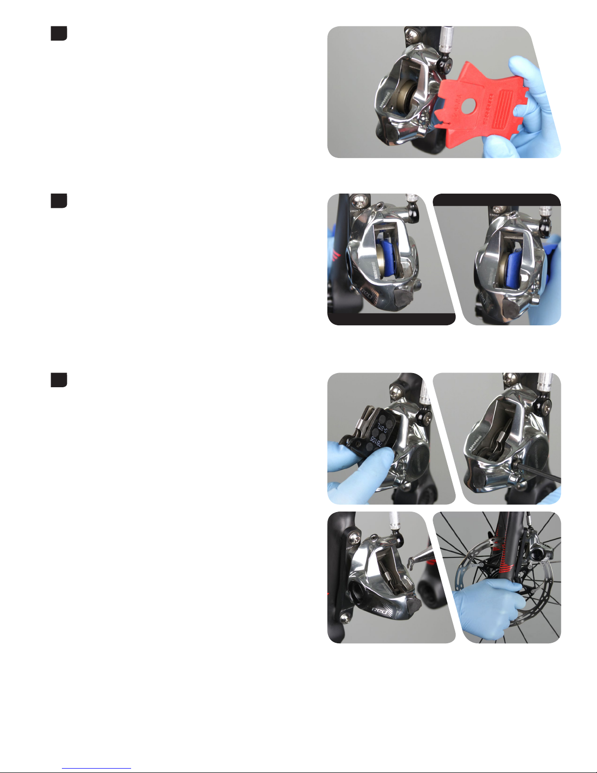
Remove the brake pads and install the pad spreader.
Squeeze the brake lever several times until both pistons have
advanced and contact the pad spreader. One piston may move faster
than the other; continue to squeeze the lever until the second piston
touches the spreader.
Bicycle work stand
1
2
Needle-nose pliers
2.5 mm
3
7
Disc Brake Pad Advancement Procedure
Remove the pad spreader.
Use a plastic tire lever to push the pistons back into the caliper bores.
Repeat steps 3-5 until both pistons contact the spreader at nearly the
same time.
Reinstall the brake pads and install the wheel according to the
manufacturer's instructions.
4
Tire lever
Tire lever
5
6

8
Disc Brake Pad Advancement Procedure
Loosen the caliper bolts.
Squeeze the brake lever several times to position the brake pads to
the proper distance from the rotor.
Center the caliper on the rotor, and tighten.
Spin the wheel and check the brake function. The pistons should move
freely and there should not be excessive brake lever throw.
If there is no improvement in the brake function, proceed to
Caliper Service.
7
T25
T25 5 N·m (44 in-lb) 22 mm
8
9

9
SRAM eTap AXS HRD Caliper Service
SRAM eTap AXS HRD Caliper Service
Parts, Tools and Supplies
Parts
• Disc Brake Caliper Piston Service Kit - 21 mm Monoblock
Safety and Protection Supplies
• Apron
• Clean, lint-free shop towels
• Nitrile gloves
• Oil pan
• Safety glasses
Lubricants and Fluids
• Isopropyl alcohol
• SRAM DOT 5.1 Fluid
If SRAM fluid is not available, only use DOT 5.1 or 4 fluid
• SRAM DOT assembly grease
SRAM Tools
• Monoblock caliper 21 mm piston removal tool
• Piston plug
• Monoblock bleed block
Bicycle Tools
• Bicycle work stand
Common Tools
• Needle nose pliers
• 2.5 mm hex wrench
• 2.5 mm hex bit socket
• T25 TORX wrench
• T25 TORX bit socket
• Air compressor with rubber-tipped air chuck nozzle
• Digital caliper
• Pick
• Torque wrench
• Soft rubber or piece of inner tube
eTap AXS HRD Caliper Exploded View
E-clip
Caliper piston
Piston seal
Brake pads
Caliper
Banjo
Hose
Banjo
bolt
Pad
retention
bolt
Piston seal
Caliper piston

10
Caliper Brake Pad Removal
Caliper Brake Pad Removal
Remove the caliper from the frame, then remove the mounting bracket
and the hardware from the caliper. Set them aside in the order that they
were removed.
Remove the E-clip from the pad retention bolt, then remove the pad
retention bolt from the caliper.
Remove the brake pads from the caliper.
NOTICE
Brake pads must be replaced if the total thickness of the backing
plate and pad friction material is less than 3 mm.
1
2
2.5 mm
3
Digital caliper 2.7-3.2 N•m (24-28 in-lb) 22 mm

11
Caliper Piston Removal
Caliper Piston Removal
NOTICE
DOT fluid will damage painted surfaces. If any fluid comes in contact with a painted surface (e.g. your frame) or printing on the brakes, wipe it off
immediately and clean it with isopropyl alcohol or water. Damage to painted and/or printed surfaces by DOT fluid is not covered under warranty.
Remove the banjo bolt and hose.
NOTICE
Fluid will drip. Place an oil pan and/or shop towel under the hose.
Insert the piston removal tool, then install the pad retention bolt into
the caliper.
⚠ CAUTION
The pad retention bolt must be installed. If the pad retention bolt is
not installed, the piston removal tool may dislodge rapidly from the
caliper, which can lead to bodily injury or damage to the parts.
Firmly press a rubber-tipped air chuck nozzle into the banjo port. Hold
the caliper securely against a rubber surface and force air into the
banjo port to dislodge the piston from the caliper.
⚠ CAUTION EYE HAZARD
Wear safety glasses. The caliper piston may dislodge rapidly from the
caliper, which can lead to bodily injury or damage to the parts. Point
the caliper piston toward a rubber surface to prevent the piston from
becoming a projectile.
1
T25 Rubber-tipped blow gun chuck nozzle 22 mm
Piston removal tool
2.5 mm
2
3
Rubber-tipped air chuck nozzle Rubber-tipped blow gun chuck nozzle 22 mm

12
Caliper Piston Removal
Remove the pad retainer bolt, then remove the piston and the piston
removal tool from the caliper.
Insert the piston plug so that it fits snugly into the empty piston bore
and is flush with the inside of the caliper.
Insert the piston removal tool so that it will capture the still-installed
piston. Make sure the horseshoe opening is aligned with the tab on the
piston plug.
Install the pad retention bolt to hold the piston removal tool in place.
⚠ CAUTION
The pad retention bolt must be installed. If the pad retention bolt is
not installed the piston removal tool may dislodge rapidly from the
caliper, which can lead to bodily injury or damage to the parts.
Piston removal tool
Piston removal tool
4
2.5 mm Rubber-tipped blow gun chuck nozzle 22 mm
Piston plug Rubber-tipped blow gun chuck nozzle 22 mm
5
Piston removal tool
2.5 mm
6

13
Caliper Piston Removal
Firmly press a rubber-tipped air chuck nozzle into the banjo port. Hold
the caliper securely against a rubber surface and force air into the
banjo port to dislodge the piston from the caliper.
⚠ CAUTION EYE HAZARD
Wear safety glasses. The caliper piston may dislodge rapidly from the
caliper, which can lead to bodily injury or damage to the parts. Point
the caliper piston toward a rubber surface to prevent the piston from
becoming a projectile.
Remove the retention bolt, the piston removal tool, the piston, and the
piston plug from the caliper.
Remove the piston seals from each piston bore.
⚠ CAUTION
Do not scratch the seal gland with the pick. Scratches could cause
fluid to leak when the brake is applied, which will contaminate the
brake pads and could lead to a brake failure.
Rubber-tipped air chuck nozzle Rubber-tipped blow gun chuck nozzle 22 mm
7
2.5 mm
8
Pick Rubber-tipped blow gun chuck nozzle 22 mm
9

14
Caliper Piston Removal
Spray isopropyl alcohol inside each piston bore, the inside and the
outside of the caliper, and all of the removed parts and clean them with
a shop towel.
NOTICE
Do not use mineral oil or DOT 5 fluid. If the brake system has
been contaminated with mineral oil or DOT 5 fluid, the braking
system (e.g. the brake-shift lever, caliper, and hose) will need to be
replaced.
For the best braking performance, use only SRAM DOT 5.1 fluid. If
SRAM fluid is not available, use only DOT 5.1 fluid or 4 fluid.
10

15
Caliper Piston Installation
Caliper Piston Installation
NOTICE
DOT fluid will damage painted surfaces. If any fluid comes in contact with a painted surface (e.g. your frame) or printing on the brakes, wipe it off
immediately and clean it with isopropyl alcohol or water. Damage to painted and/or printed surfaces by DOT fluid is not covered under warranty.
Apply a small amount of SRAM 5.1 DOT fluid to new piston seals and
install the piston seals into each piston bore.
Inspect the caliper pistons for damage and replace the pistons if
necessary.
Use your gloved finger to apply a small amount of SRAM DOT 5.1 fluid
to each piston, then install each piston into each piston bore.
NOTICE
For the best braking performance, use only SRAM DOT 5.1 fluid. If
SRAM fluid is not available, use only DOT 5.1 or 4 fluid. Do not use
grease. Grease will prevent the pistons from fully retracting into the
caliper bores which will reduce braking performance.
Tip: If a piston is difficult to install into a piston bore, lay the caliper on
a flat surface. Slide a thin wrench through the caliper, then gently and
evenly press the piston into the bore.
1
2
SRAM DOT 5.1 fluid Rubber-tipped blow gun chuck nozzle 22 mm

16
Caliper Piston Installation
Remove the o-rings from the banjo bolt.
Install the new o-rings and apply a thin layer of grease.
Tighten the banjo bolt with the banjo boot at the desired angle.
Insert the Monoblock bleed block into the caliper, then install the pad
retention bolt.
⚠ CAUTION
You must bleed your brakes before reinstalling the brake pads.
Installing the brake pads prior to bleeding the brakes could
contaminate the brake pads and could lead to a brake failure.
Spray isopropyl alcohol on the caliper and clean it with a shop towel.
Visually check your work. If any of the o-rings protrude from the banjo fitting or banjo bolt, remove and replace the o-ring, then repeat the
installation process.
⚠ CAUTION
Servicing your brakes removes all of the brake fluid from the system. You must bleed your brakes after you service the brake caliper. Consult the
eTap AXS HRD Hose Shortening and Bleed Manual at www.sram.com/service.
3
DOT grease
4
T25 5 N·m (44 in-lb)
5
Monoblock bleed block 20 mm or 15 mm Thru Axle
2.5 mm QR
6

17
SRAM eTap AXS HRD Hose Replacement
SRAM eTap AXS HRD Hose Replacement
Perform the hose replacement service if the hose needs to be replaced. For hose shortening instructions, consult the eTap AXS HRD Hose Shortening
and Bleed Manual at www.sram.com/service.
Parts, Tools and Supplies
Parts
• Disc Brake Hose Hood Assembly - SRAM RED eTap
Safety and Protection Supplies
• Apron
• Clean, lint-free shop towels
• Nitrile gloves
• Oil pan
• Safety glasses
Lubricants and Fluids
• Isopropyl alcohol
• SRAM DOT assembly grease
SRAM Tools
• SRAM hydraulic hose cutter tool
• Monoblock bleed block
Common Tools
• Needle nose pliers
• 2.5 mm hex wrench
• 2.5 mm hex bit socket
• T8 and T25 TORX wrenches
• T25 TORX bit socket
• 8 mm flare nut wrench
• 8 mm crowfoot wrench
• 10 mm open end wrench
• Torque wrench
• Marker
Hose Removal
Remove the wheel from the bicycle according to the manufacturer's
instructions.
Remove the E-clip from the pad retention bolt, then remove the pad
retention bolt from the caliper.
1
2
Needle nose pliers 20 mm or 15 mm Thru Axle
2.5 mm QR

18
Hose Removal
Remove the brake pads from the caliper.
NOTICE
Brake pads must be replaced if the total thickness of the backing
plate and pad friction material is less than 3 mm.
Install the Monoblock bleed block into the caliper, then install the pad
retention bolt.
Digital caliper
3
Monoblock bleed block 20 mm or 15 mm Thru Axle
2.5 mm QR
4

19
Hose Removal
Loosen and remove the compression nut and hose from the
valve body.
Loosen and remove the banjo bolt and the hose from the caliper.
NOTICE
Fluid will drip. Place an oil pan and/or shop towel under the caliper.
Remove the hose from the frame, according to your frame
manufacturer's instructions.
To remove the hose from internally routed frames, first cut the hose
near the compression fitting and remove the compression nut from the
hose.
5
Flare nut wrench: 8 mm Open end wrench: 10 mm
T25
6
7

20
Hose Installation
Hose Installation
Internally routed frames: Insert the hose and route it through the
frame or fork.
Externally routed frames: Loosely connect the hose to the frame or
fork.
Apply a thin layer of grease to the banjo bolt o-rings, then install the
banjo bolt into the new banjo.
Install the new banjo onto the caliper.
To shorten the hose, hold the hose up to the shift-brake lever with a
length that creates a gentle bend in the hose and allows the handlebar
to freely turn from side to side.
Mark your cut location, then cut the hose.
NOTICE
You must cut the hose at the lever. Cutting the hose at the caliper
will remove the crimped banjo from the hose, and it will need to be
replaced.
1
DOT grease
2
T25 5 N·m (44 in-lb)
3
4
Hydraulic hose cutter

21
Hose Installation
Apply grease to the hose barb threads.
Thread the hose barb into the hose until it is flush with the end of the
hose.
Install the compression nut onto the hose.
NOTICE
Do not overtighten the hose barb. Overtightening may cause damage
to the hose liner.
Thread a new compression fitting over the hose barb, counterclockwise, until it is flush or slightly lower than the hose barb.
The compression fitting is reverse threaded.
NOTICE
You must install a new hose barb and compression fitting before
reconnecting the brake lever to the hose.
Apply a thin layer of grease to the compression fitting and compression
nut.
5
DOT grease
6
T8
7
8
DOT compatible grease

22
Hose Installation
Install the hose into the lever body while threading the compression
nut into the valve body by hand. Tighten the compression nut.
⚠ CAUTION
Hydraulic hose replacement removes all of the fluid from the system. You must bleed your brakes after you service the brake caliper. Consult the
eTap AXS HRD Hose Shortening and Bleed Manual at www.sram.com/service.
9
8 mm 8 N·m (71 in-lb) 10 mm

23
Electronic Subassembly Replacement
Electronic Subassembly Replacement
Perform the Electronic Subassembly replacement if your brake lever, shifter, or battery box has been damaged.
Parts, Tools and Supplies
Parts
• SRAM RED eTap AXS Hydraulic Road Brake Lever Assembly - Left or
Right
Safety and Protection Supplies
• Apron
• Nitrile gloves
• Safety glasses
Common Tools
• (2) 2.5 mm hex wrenches
• 2.5 mm hex bit sockets
• T6 TORX wrench
• T6 TORX bit socket
• Torque wrench
Electronic Subassembly Exploded View
Pivot Pin
Bolt
Electronic
Subassembly
Pivot Pin Nut
Battery Box
Screws
Auxiliary Connector
Cover and Screws
Pull Rod
Bushing
Bushing

24
Electronic Subassembly Removal
Electronic Subassembly Removal
If the hood cover has been damaged, remove the hood cover for easier access to the electronic subassembly. Install a new cover after the service is
complete.
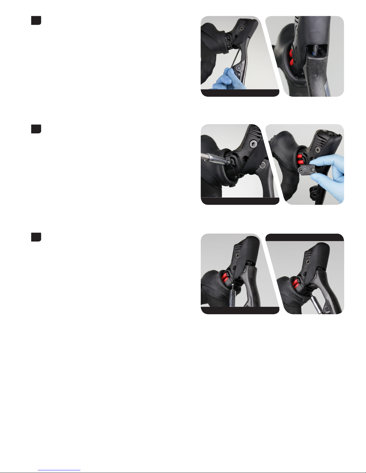
Fold the hood cover forward and remove the SRAM eTap AXS Blips or
seal plugs from the electronic subassembly.
Remove the screw from the auxiliary connector cover, then fold the
hood cover backward.
Hold the pivot pin nut in place, then unthread the pivot pin bolt from
the hood assembly.
For best performance, make sure the pivot pin bushings remain on the
pivot pin nut and bolt.
1
2
T6
2.5 mm 2.5 mm
3
25
Electronic Subassembly Removal
Rotate the reach adjust bolt clockwise to unthread the lever from the
hood.
The reach adjust bolt is reverse-threaded.
Remove the second auxiliary connector cover screw, then remove the
auxiliary connector cover from the hood assembly.
Remove the battery box screws.
2.5 mm
4
5
T6
T6
T6
6

26
Electronic Subassembly Removal
Remove the lever and the battery box from the hood assembly, then
remove the auxiliary connectors from the hood assembly.
7

27
Electronic Subassembly Installation
Electronic Subassembly Installation
Install the auxiliary connectors into the hood so the auxiliary connector
with the longer wire is in the top slot. Install the battery box into the
hood, making sure the wires are routed beneath the battery box
without being pinched.
NOTICE
Do not pinch the electronic subassembly wires when installing the
battery block into the hood assembly. Pinching the wires can lead to
shifter malfunction or damage to the wires.
Install the longer screw into the auxiliary connector cover and gently
tighten.
NOTICE
Do not overtighten the screws. Overtightening the screws can
damage the hood assembly.
Install the shorter screws into the battery box and gently tighten.
NOTICE
Do not overtighten the screws. Overtightening the screws can
damage the hood assembly.
1
T6
2
3
T6
T6

28
Electronic Subassembly Installation
Insert the lever into the hood assembly. Insert a 2.5 mm hex wrench
into the reach adjust bolt hole in the lever and align the wrench with
the pull rod. Push the lever into the hood assembly, and rotate the bolt
counter-clockwise to tighten the bolt to hand tight.
The reach adjust pull rod is reverse-threaded.
Install the pivot pin nut and the pivot pin bolt into the hood. Hold the
nut in place, then tighten the pivot pin bolt.
Adjust the reach to your desired setting.
Rotate the reach adjust screw clockwise to move the lever toward
the handlebar, or counter-clockwise to move the lever away from the
handlebar.
2.5 mm
2.5 mm
4
5
2.5 mm 1.2 N·m (11 in-lbs) 2.5 mm
6
2.5 mm

29
Electronic Subassembly Installation
Fold the hood cover forward. Install the second cover screw into the
auxiliary connector cover and gently tighten. Install SRAM eTap AXS
Blips into the auxiliary ports, or leave the seal plugs in place. Fold the
hood cover down.
NOTICE
Do not overtighten the screws. Overtightening the screws can
damage the hood assembly.
Do not use SRAMAXS shifters without Blip or Clic wires or seal plugs
installed. Moisture will damage the electronic components.
Your eTap AXS system must be paired before riding. Consult the Quick Start Guide Road eTap AXS Systems or the eTap AXS Systems User Manual for
pairing information at www.sram.com/service.
7
T6

These are registered trademarks of SRAM, LLC:
1:1®, Accuwatt®, Avid®, Bar®, Blackbox®, BoXXer®, DoubleTap®, Elita®, eTap®, Firecrest®, Firex®, Grip Shift®, GXP®, Hammerschmidt®, Holzfeller®,
Hussefelt®, i-Motion®, Judy®, Know Your Powers®, NSW®, Omnium®, Pike®, PowerLock®, Quarq®, Qollector®, RacerMate®, Reba®, Rock Shox®,
Ruktion®, Service Course®, ShockWiz®, SID®, Single Digit®, Speed Dial®, Speed Weaponry®, Spinscan®, SRAM®, SRAM APEX®, SRAM EAGLE®, SRAM
FORCE®, SRAM RED®, SRAM RIVAL®, SRAM VIA®, Stylo®, Torpedo®, The Power of Bicycles®, Truvativ®, Varicrank®, Velotron®,
World Bicycle Relief®, X0®, X01®, X-SYNC®, XX1®, Zed tech®, ZIPP®
These are registered logos of SRAM, LLC:
These are trademarks of SRAM, LLC:
10K™, 1X™, 202™, 30™, 302™, 303™, 404™, 454™, 808™, 858™, ABLC™, AeroGlide™, AeroBalance™, AeroLink™, Airea™, Air Guides™, AKA™, AL-7050-TV™,
Automatic Drive™, Automatix™, AxCad™, Axial Clutch™, AXS™, BB5™, BB7™, BB30™, Bleeding Edge™, Blipbox™, BlipClamp™, BlipGrip™, Blips™, Bluto™,
Bottomless Tokens™, Cage Lock™, Carbon Bridge™, Centera™, Charger 2™, Charger™, Clickbox Technology™, Clics™, Code™, Cognition™, Connectamajig™,
Counter Measure™, DD3™, DD3 Pulse™, DebonAir™, Deluxe™, Deluxe Re:Aktiv™, Descendant™, DFour™, DFour91™, Dig Valve™, DirectLink™, Direct
Route™, DOT 5.1™, Double Decker™, Double Time™, Dual Flow Adjust™, Dual Position Air™, DUB™, DZero™, E300™, E400™, Eagle™, E-Connect4™,
E-matic™, ErgoBlade™, ErgoDynamics™, ESP™, EX1™, Exact Actuation™, Exogram™, Flow Link™, FR-5™, Full Pin™, Guide™, GX™, Hard Chrome™, Hexfin™,
HollowPin™, Howitzer™, HRD™, Hybrid Drive™, Hyperfoil™, i-3™, Impress™, Jaws™, Jet™, Kage™, Komfy™, Level™, Lyrik™, MatchMaker™, Maxle™, Maxle
360™, Maxle DH™, Maxle Lite™, Maxle Lite DH™, Maxle Stealth™, Maxle Ultimate™, Micro Gear System™, Mini Block™, Mini Cluster™, Monarch™, Motion
Control™, Motion Control DNA™, MRX™, Noir™, NX™, OCT™, OmniCal™, OneLoc™, Paragon™, PC-1031™, PC-1110™, PC-1170™, PG-1130™, PG-1050™, PG1170™, Piggyback™, Poploc™, Power Balance™, Power Bulge™, PowerChain™, PowerDomeX™, Powered by SRAM™, PowerGlide™, PowerLink™, Power
Pack™, Power Spline™, Predictive Steering™, Pressfit™, Pressfit 30™, Prime™, Qalvin™, R2C™, RAIL™, Rapid Recovery™, Re:Aktiv ThruShaft™, Recon™,
Reverb™, Revelation™, Riken™, Rise™, ROAM™, Roller Bearing Clutch™, RS-1™, Sag Gradients™, Sawtooth™, SCT - Smart Coasterbrake Technology,
Seeker™, Sektor™, SHIFT™, ShiftGuide™, Shorty™, Showstopper™, Side Swap™, Signal Gear Technology™, SL™, SL-70™, SL-70 Aero™, SL-70 Ergo™,
SL-80™, Sl-88™, SLC2™, SL SPEED™, SL Sprint™, Smart Connect™, Solo Air™, Solo Spoke™, SpeedBall™, Speed Metal™, SRAM APEX 1™, SRAM Force
1™, SRAM RIVAL 1™, S-series™, Stealth-a-majig™, StealthRing™, Super-9™, Supercork™, Super Deluxe™, Super Deluxe Coil™, SwingLink™, TaperCore™,
Timing Port Closure™, Tool-free Reach Adjust™, Top Loading Pads™, Torque Caps™, TRX™, Turnkey™, TwistLoc™, Tyrewiz™, VCLC™, Vivid™, Vivid
Air™, Vuka Aero™, Vuka Alumina™, VukaBull™, Vuka Clip™, Vuka Fit™, Wide Angle™, WiFLi™, X1™, X5™, X7™, X9™, X-Actuation™, XC™, X-Dome™, XD™,
XD Driver Body™, XDR™, XG-1150™, XG-1175™, XG-1180™, XG-1190™, X-Glide™, X-GlideR™, X-Horizon™, XLoc Sprint™, XX™, Yari™, Zero Loss™
Specifications and colors subject to change without prior notice.
© 2019 SRAM, LLC
This publication includes trademarks and registered trademarks of the following companies:
TORX® is a registered trademark of Acument Intellectual Properties, LLC
30

ASIAN HEADQUARTERS
SRAM Taiwan
No. 1598-8 Chung Shan Road
Shen Kang Hsiang, Taichung City
Taiwan R.O.C.
WORLD HEADQUARTERS
SRAM LLC
1000 W. Fulton Market, 4th Floor
Chicago, Illinois 60607
U.S.A.
EUROPEAN HEADQUARTERS
SRAM Europe
Paasbosweg 14-16
3862ZS Nijkerk
The Netherlands
 Loading...