

Page 1
1
250 H2O Welder
Operating Manual
Congratulations on the purchase of your SRA-250 H20 Welder. With this welding
unit you can now experience the many advantages of the H20 welding process.
The SRA-250 has been designed to use low voltage electricity to dissociate water
into hydrogen and oxygen. It is safe, simple and reliable and ideal for quick, clean
soldering and brazing.
Page 2
2
TABLE OF CONTENTS
Features …………………………………………………………………………………………….……..……..3
Package Contents………………………………………………………………………………….………….3
Specifications……………………………………………………………………………………………………3
Safety Precautions………………………………………………………………………………….………..4
Welder Diagram………….……………………………………………………………………….…………..5
Part List for Welder Diagram………………………………………………………………………….…6
Using the H20 Welder…………..……………………………………………………………….…………7
Routine Maintenance..…………..…………………………………………………………………….....9
Tip Size Chart and Power Control Setting………………………………………………………..11
Warranty Information………..………………………………………………………………………..…12
24 Walpole Park South, STE #10
Walpole, MA 02081
508-688-6044
1-800-545-4570
www.sra-shops.com
Page 3
3
Features and Package Contents
Model
Size
Weight
Max Power Watts
Current
SRA-250
11 x 9.6 x 11’’H
31 lbs.
190
110V
Features:
Clean Pin Point Flame with Temperatures Up to 5000°F from a Pen Size Torch.
The torch tip is a hydrodermic needle.
Electronic indicator lights for distilled water level.
Package Contents:
1 torch
Electrolyte
Tips
Specifications:
*220V available by special order
Page 4
4
SAFETY PRECAUTIONS
CAUTION
BEFORE SETTING UP, OPERATING OR MAINTANING THIS
MACHINE, PLEASE READ THE ENTIRE CONTENTS OF THE
MANUAL CAREFULLY. MAKE SURE YOU UNDERSTAND THE
SAFETY RULES AND HAZARDS FOUND BELOW AND
THROUGHOUT THE OPERATING MANUAL
Please Refer to the Following Safety Standards:
NEVER unscrew the water tank or booster tank unless the machine is turned off
NEVER use metal prongs or wire in the water tank
NEVER change tips without first putting out the flame. The machine can remain
on when removing tips.
NEVER light torch until you can feel a sufficient amount of gas coming from the
tip of the torch
NEVER turn the machine on when the booster tank is EMPTY
WARNING! AVOID ANY CONTACT WITH CAUSTIC SOLUTION. It is very corrosive.
Avoid contact with eyes or skin. If in contact with skin, wash immediately with
water to avoid caustic burns.
WARNING! DO NOT have a lit cigarette or open flame near the machine when
either tank is open or when maintenance is being done on the machine.
Page 5
5
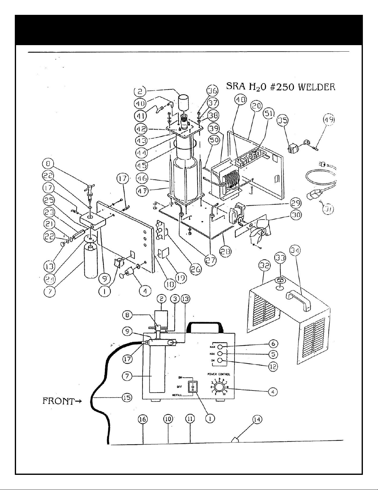
WELDER DIAGRAM
Page 6
6
PARTS LIST FOR WELDER DIAGRAM
#
PART DESCRIPTION
#
PART DESCRIPTION
#
PART DESCRIPTION
#
PART DESCRIPTION
1
Three position
switch
16
Torch Hose Fitting
31
Power cable
46
Tank
2
Safety cap
17
Fitting 1/8’’
32
Cover
47
Rod Ø 6mm
3
Filling Neck
18
Front panel
33
Rubber ring
48
Register 5k 110v
10k 220v
4
Power control knob
19
Power control 110v220v
34
Handle
49
4a. fuse
5
Minimum level
indicator light
20
Rear panel
35
Fuse holder plug
50
Power transformer
terminal
6
Maximum level
indicator light
21
Brass screw for check
valve
36
Nut 6MA
51
RFI suppression
filter
7
Booster
22
Cap & tee screw Oring
37
Washer 6 mm
8
Tee screw
23
Check valve
38
Insulator Ø 6mm
9
Booster holder with
1/8’’ fitting
24
Booster seal gasket
39
Power transformer
110v-220v
10
Torch
25
Check valve O-ring
40
Fitting 1/8’’ 90°
11
Tips
26
Level circuit board
41
Rilsan tube 4x6 mm
12
On indicator light
27
Rectifier diodes
42
Minimum level
sensor
13
Check valve cap
28
Aluminum base plate
43
Tank cover
14
Torch holder/stand
29
Fan motor 110v-220v
44
Maximum level
sensor
15
Torch hose
30
Fan
45
Tank O-ring
Page 7

7
USING THE H20 WELDER
Start Up:
1. Plug electric cord to appropriate 110V 220V electrical outlet. Push
the off/on switch to fill position.
2. Locate the chrome cap on top of the cabinet. This is the inlet to the
water tank. Unscrew the cap using the large funnel provided. Pour
entire contents of caustic “C” solution into the water tank. As you
start pouring the electrolyte into the tank, the minimum light will go
off. Now both lights will be off until the red maximum light goes on.
NOTE: If the red light does not come on, then add a very small
amount of distilled water until it does.
CAUTION: DO NOT add water once the red light comes on. Too much
water will cause water to accumulate in the gas output torch hose,
resulting in an inconsistent flame.
3. Find the booster tank located in the front of the cabinet. Unscrew
the T-handle to remove the booster tank. Carefully pour methyl
alcohol (also known as Methanol) into the tank, use the small funnel
so that the fluid does not enter the center section of the tank.
NOTE: Boric acid powder can be added to the methyl alcohol
solution in a ratio of .5 to .7 ounces per quart. This should be
premixed. Boric acid with methyl alcohol provides a reducing
characteristic to the flame. Fill the booster tank to the fill mark.
Screw the booster tank back in place with the T-handle. Tighten the
T-handle finger tight.
CHECK THE LEVEL OF FLUID IN THE BOOSTER TANK EVERY FOUR
HOURS OF RUNNING TIME. THE MACHINE SHOULD NEVER BE RUN
Page 8

8
WITHOUT THE CORRECT AMOUNT OF METHYL ALCOHOL SOLUTION
IN THE BOOSTER TANK. EMPTY THE BOOSTER TANK EVERY 12-16
HOURS OF RUNNING TIME. WASH THE TANK IN HOT WATER AND
DRY BEFORE USING.
4. Press on the proper size tip to the end of the torch. (See tip size
chart on page 11)
5. Turn the machine on by pushing the on/off switch to ON position.
Turn the round knob so that it corresponds to the setting in the tip
chart. In 30 seconds to 1 minute, you can feel gas flowing out of the
tip of the torch and hear gas bubbling in the booster tank. When this
occurs, light the torch. If more gas is required, turn the knob to a
higher position.
a. Conversely, if less gas is required, turn the knob to a lower
position. Use the lower position for tips with smaller orifice.
CAUTION: NEVER light the torch until you can feel gas coming from
the tip of the torch. Never change the tips without first putting out
the flame. The machine can remain on when removing tips.
6. To turn off the machine first put out the flame. To put out the flame
push in the back of the torch. When the flame is out, shut off the
machine. Always leave the tip open to allow gas to escape.
CAUTION: ALWAYS remove the booster tank before opening the
water tank cover. This is to prevent methyl alcohol solution from
being sucked into the water tank and contaminating it.
Page 9

9
Routine Maintenance
It is essential to perform daily maintenance on your welder. Each day
before starting your SRA H20 Welder, perform the following steps and
cautions:
1. Remove the booster tank and check the level of methyl alcohol
solution. If required, add solution till it reaches the maximum level
mark. EVERY FOUR HOURS OF RUNNING TIME CHECK THE LEVEL
AND FILL. At the end of 12-16 hours of running time, empty the tank
and wash in hot water. Dry the tank and pour in a new solution.
BEFORE REMOVING THE CAP FROM THE DISTILLED WATER TANK,
FIRST REMOVE THE ALCOHOL BOOSTER TANK FROM THE MACHINE,
AND THEN REMOVE THE CAP. THIS WILL PREVENT ALCOHOL FROM
BEING SUCKED BACK INTO THE DISTILLED WATER TANK, WHICH
WOULD CAUSE CONTAMINATION OF THE SOLUTION.
2. Check the water level by turning the toggle switch to the REFILL
position. Observe the water level indicator lights:
a. If the MAXIMUM RED light is on DO NOT add distilled water
b. If BOTH lights are off, or YELLOW MINIMUM light is on,
unscrew the water tank cap and add distilled water
STOP IMMEDIATELY WHEN THE RED LIGHT COMES ON
Warning! DO NOT add distilled water beyond the maximum point
when the red light comes on. Too much water in the tank will cause
water to accumulate in the plastic torch hoses. This results in an
inconsistent flame. Screw the cap back on tight.
c. If MINIMUM GREENISH YELLOW light comes on DO NOT
operate the machine. Fill with distilled water until the red light
comes on.
Page 10

10
NOTE: When operating the machine, the red light will go off and no
lights will be on. This is normal operating level. When the greenish
yellow light goes on STOP immediately and add some distilled water.
CAUTION: NEVER OPERATE THE MACHINE WHEN THE MINIMUM
LIGHT IS ON
3. When filling with distilled water, the minimum light will go off first.
Both lights will be off until the full mark is reached. At that time, the
red light will go on.
4. Screw the water cap on tight. Screw the booster tank back to the
booster holder with T-handle.
NOTE: EVERY EIGHT HOURS CHECK BOTH THE DISTILLED WATER
LEVEL AND BOOSTER TANK LEVEL. IT IS BEST TO FILL TANKS AT THE
START OF EACH DAY. ELECTROLYTE CAUSTIC SOLUTION WILL
USUALLY FUNCTION FOR AT LEAST SIX MONTHS TO ONE YEAR.
WHEN THE SOLUTION BECOMES WEAK, POUR OUT ENTIRE
CONTENTS AND THEN FLUSH SEVERAL TIMES WITH DISTILLED
WATER UNTIL THE WATER APPREARS CLEAN. THEN ADD NEW
CAUSTIC SOLUTION.
Page 11
11
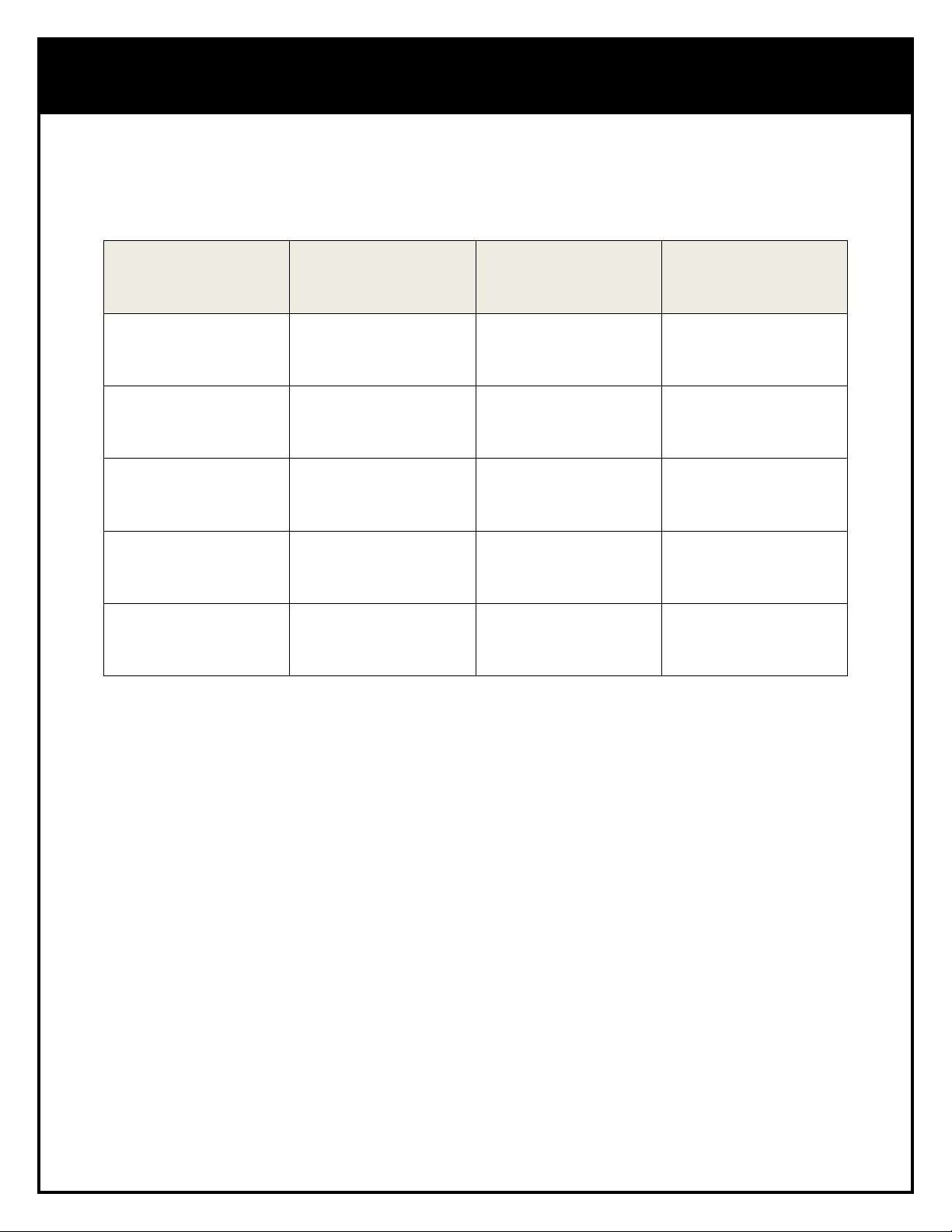
TIP SIZE AND POWER CONTROL SETTING
NUMBER OF
TORCHES
GAUGE
BURNER TIP
I.D. COLOR
POWER CONTROL
SETTINGS
1
25
.010 RED
5-6 1
23
.013 ORANGE
6-8 1
22
.016 BLUE
8-9 1
21
.020 LT PURPLE
8-10
1
20
.023 PINK
9-10
SELECTION CHART FOR TIP SIZE & POWER CONTROL SETTING
Page 12

12
Warranty Information
1-YEAR LIMITED WARRANTY
Your H20 welder is warranted to the original purchaser for 1 year
from the date of purchase; to be free from defects in materials and
workmanship (but not against damages caused by misuse, negligence,
accident, and faulty installation or by using materials incompatible with
the equipment.)
SRA Soldering Products
www.sra-solder.com
 Loading...