

Page 1

Squirrel Workstation 8
SQ-2020
Operator and Service
Manual
Revision 1.0
Page 2

Preliminary Release
Caution: Changes or modifications to this equipment, not expressly approved by the
manufacturer could void the user’s authority to operate the equipment.
Information in this document is subject to change without
notice. No part of this document may be reproduced or
transmitted in any form or by any means, electronic or
mechanical, for any purpose, without the express written
permission of Squirrel Systems.
© 2003 Squirrel Systems. All rights reserved.
Page 3

Squirrel Workstation 8
Records of Revision
Date
Reference:
Page,
Paragraph,
Revision
No.
Comments
Check
and
Approval
Drawing No.
Mar 31/05 Rev 1.0 Initial Release D. O’Brien
Page 4

TABLE OF CONTENTS
CHAPTER 1: GENERAL INFORMATION................................... 1-1
INTRODUCTION............................................................................................ 1-1
SPECIFICATIONS ......................................................................................... 1-2
ACCESSORIES ............................................................................................. 1-4
WORKSTATION 8 DIMENSIONS ................................................................. 1-5
PRODUCT DESCRIPTION............................................................................ 1-7
CHAPTER 2: DISASSEMBLY and ASSEMBLY........................ 2-1
General Servicing Precautions................................................................... 2-1
Service Equipment and Parts List.............................................................. 2-1
Removing the Front Cover......................................................................... 2-5
Replacing the Front Cover ......................................................................... 2-7
Removing the Mag Swipe Reader.............................................................. 2-7
Removing the ISIS Badge Reader (Optical Reader) ................................. 2-8
Removing the ‘DG41 LCD Assembly (Mounting Bracket) from the Rear
Internal Shield Assembly
Disassembly of the ‘DG41 LCD Assembly...............................................2-13
Removing the Touch Screen Sensor (Overlay) ............................. 2-13
Reassembling/Replacing the Touch Screen Sensor (Overlay) ..... 2-14
Removing the ‘DG41 LCD from the LCD Mounting Bracket.......... 2-14
Disconnecting the LCD Data Cable ............................................... 2-16
Removing the Open Frame Inverter...............................................2-16
Reassembly.................................................................................... 2-17
Base Bottom Disassembly ....................................................................... 2-18
Disconnecting the Power Switch Cable from the Motherboard ..... 2-18
Disassembly of the Internal Shield Assembly ................................ 2-19
Removing the Motherboard from the Internal Shield Housing2-21
Resetting CMOS for Squirrel Defaults ................................... 2-22
Removing the Card Guide Rails............................................. 2-23
TABLE OF CONTENTS
.......................................................................... 2-11
Removing the Internal Shield Assembly out of the Base Bottom
Plastics
Removing the Power Switch Cable and the Power Switch....2-19
Removing the Intake Fan....................................................... 2-20
................................................................................... 2-19
CHAPTER 3: INSTALLATION ................................................... 3-1
I Preliminary Release 3/24/05/R1.0
GENERAL GUIDELINES............................................................................... 3-1
ELECTRICAL POWER REQUIREMENTS.................................................... 3-2
LOCATION AND MOUNTING POSITIONS .................................................. 3-2
Page 5

TABLE OF CONTENTS
PROPER INSTALLATION OF MOUNTING HARDWARE............................3-3
Tilt Stand (92-205) Installation....................................................................3-3
Adjusting the Tilt Stand...............................................................................3-6
Mounting the Workstation 8 to a Wall Bracket (92-207).............................3-8
Wall Mount........................................................................................3-8
Counter Sunk Mount.........................................................................3-9
HOST/SERVER COMMUNICATION PROTOCOL........................................3-9
ISIS BADGE READER CONFIGURATION .................................................3-10
CABLE LOCATION LABEL - I/O INTERFACE..........................................3-10
TYPICAL WORKSTATION & PERIPHERAL SETUP.................................3-12
FINAL TESTING OF THE INSTALLATION.................................................3-13
Powering it On...........................................................................................3-13
Screen Contrast........................................................................................3-14
Volume Control .........................................................................................3-14
CHAPTER 4: MAINTENANCE....................................................4-1
CARING FOR THE WORKSTATION 8..........................................................4-1
General Cleaning........................................................................................4-1
Cleaning the Credit Card Reader ...............................................................4-2
CHAPTER 5: TROUBLESHOOTING .........................................5-1
CHAPTER 6: APPENDICES.......................................................6-1
APPENDIX A: ESD WORK-STATION...........................................................6-1
Maximum Allowable Resistances and Discharge Times for Static Safe
Operations
ESD Work-station Do’s and Don’ts.............................................................6-2
Prime Sources of Static Electricity in an Electronics Work Area................6-3
Field Service - ESD Prevention ..................................................................6-4
Field Service Kit..........................................................................................6-4
APPENDIX B: LCD HANDLING ....................................................................6-5
ESD Protection............................................................................................6-5
Mechanical Force and Strength..................................................................6-5
Handling the LCD........................................................................................6-5
Cleaning......................................................................................................6-6
Storage........................................................................................................6-6
Ingestion and Injury Warning......................................................................6-7
..............................................................................................6-2
APPENDIX C: HANDLING CIRCUIT BOARDS ............................................6-8
APPENDIX D: PORT SIGNAL PIN ASSIGNMENT.......................................6-9
II Preliminary Release 3/24/05
Page 6

TABLE OF CONTENTS
APPENDIX E: TOUCHSCREEN SENSOR ................................................. 6-10
Cleaning ................................................................................................... 6-10
Specifications ........................................................................................... 6-10
APPENDIX F: MOTHERBOARD PREPARATION ..................................... 6-12
Foil Taping the Rear Shield Casing (89-541)...........................................6-13
Foil Tape Specifications........................................................................... 6-14
APPENDIX G: ............................................................................................ 6-15
Connector Descriptions............................................................................ 6-15
Jumper Descriptions................................................................................. 6-16
Jumper Settings Information .................................................................... 6-17
APPENDIX H: BUTTERFLY SHIELD SCREW.......................................... 6-21
APPENDIX I: LCD BRACKET PREPARATION FOR MOUNTING THE
LQ121S1DG41 DISPLAY
............................................................................ 6-22
3/24/05 Preliminary Release III
Page 7

CHAPTER 1: GENERAL INFORMATION
The General Information Chapter includes three sections:
• Introduction
• Specifications
• Accessories
• Product Dimensions
• Product Description
GENERAL INFORMATION
INTRODUCTION
This publication is intended to provide technical support information for Squirrel
systems installers, field service technicians and depot service technicians.
Information in this manual includes:
• Specifications for electrical power requirements and interface
installation.
• Installation guidelines for mounting hardware and procedures pertaining
to the Wall Bracket and Tilt Stand
• Assembly and disassembly procedures.
cable
Only authorized SQUIRREL personnel with proper training and equipment such as
Anti-static Kits should attempt the disassembly procedures described in this manual.
1-1 R1.0 Preliminary Release 3/24/05
• Configuration and adjustment of communication protocol, display
attributes and other features.
• Troubleshooting and repair procedures.
Page 8
SPECIFICATIONS
GENERAL INFORMATION
Standard SBC
Functions
PROCESSOR
BIOS
SYSTEM CHIPSET
SECOND LEVEL OF CACHE
RAM
PARALLEL PORT
SERIAL PORTS
Intel Celeron 850 MHz or Pentium 3 up
to 1GHz
- Socket 370
- Standard Award® PC 256 KB Flash
BIOS
- Includes ETHERNET LINUX boot
ROM
VIA VT82C694/VT82C686
On-board 512KB
- two 168 - pin DIMM sockets
(supports up to 512MB SDRAM)
- One parallel port (LPT2)
onboard/internal access, supporting
SPP/EPP/ECP/ parallel mode.
- COM 1 & 2 External
RJ11: RS-232
- COM 4 External
RJ11: RS232 & supports +5V
power
Ethernet Interface
KEYBOARD CONNECTOR
PS/2 MOUSE CONNECTOR
VIDEO CONNECTOR
WATCHDOG TIMER
USB
CHIP
ETHERNET INTERFACE
- COM 1,2 & 3 Onboard
2x5 Header: RS-232
Mini-DIN keyboard connector
PS/2 mouse – onboard/internal access
Internal shrouded header to support a
CRT monitor
Software enable/disable. Time interval of
1.6 seconds generates system reset in
the event of program failure
Two onboard/internal access USB1.1
RTL8139C
10/100 BASE-T/TX, RJ45
1-2 Preliminary Release 3/24/05
Page 9
GENERAL INFORMATION
Flat Panel / PCI
SVGA Interface:
Touchscreen
Interface
Cash Drawer
Interface:
Peripherals Devices
Software
Compatibility
CHIPSET
DISPLAY MEMORY
DISPLAY TYPE
C & T 69000
- 2 MB integrated memory
2 MB on-board memory
- 12.1” Color TFT – Hi Brightness LCD
- Resolution: 800x600
OVERLAY
5 Wire 12.1” ELO-Touch Analogue
Resistive overlay
CASHDRAWERS
Supports 2 cash drawers.
(RJ11 connector)
MAGNETIC SWIPE
SOFTWARE POS SquirrelOne
Bi-directional read Track 1 & Track 2
External Power
Supply Adaptor
INPUT REQUIREMENTS
OUTPUT REQUIREMENTS
POWER CORD LENGTHS
SIZE (DIMENSIONS)
- 100 VAC – 240 VAC
- 50-60 Hz (International)
- UL and CE
- +12V, DC @ 5.5 Amps
- maximum power rating: 60 WATTS
CONT.
- input approx.: 40” (1016mm)
- output approx.: 72” (1830mm)
- L x W x D:
132”(5.20mm)x58”(2.29mm)x
30”(1.18mm)
- Weight: 0.66 lbs (300g)
3/24/05 Preliminary Release 1-3
Page 10

Mechanical and
Environmental
OPERATING TEMPERATURE
OPERATING HUMIDITY
GENERAL INFORMATION
50° to 105.8° F (10° to 40° C)
5% to 95% relative humidity
ACCESSORIES
WEIGHT
ETHERNET CABLE
CHECK PRINTER COMMUNICATION
CABLE
EXTERNAL POWER SUPPLY WITH
POWER CORD
CASH DRAWER CABLE
CUSTOMER DISPLAY TOWER CABLE
ADJUSTABLE TILT STAND
MAG SWIPE (CREDIT CARD
READER)
12.47 lbs (5.64 kg) WS on stand
7.10 lbs (3.22 kg) WS only
Standard
Standard
Standard
Optional
Optional
Standard
Optional
1-4 Preliminary Release 3/24/05
Page 11

WORKSTATION 8 DIMENSIONS
GENERAL INFORMATION
3/24/05 Preliminary Release 1-5
Page 12
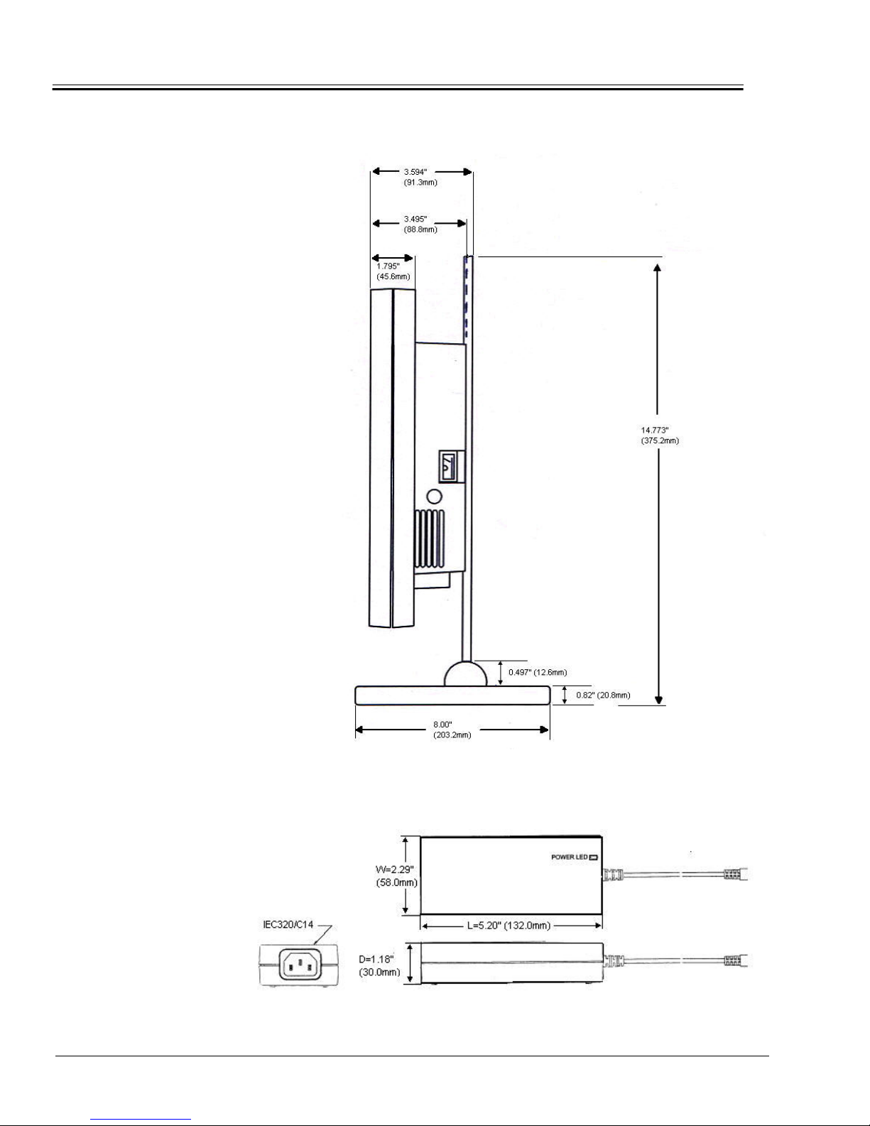
Side Dimensions
GENERAL INFORMATION
External Power Supply Dimensions
1-6 Preliminary Release 3/24/05
Page 13
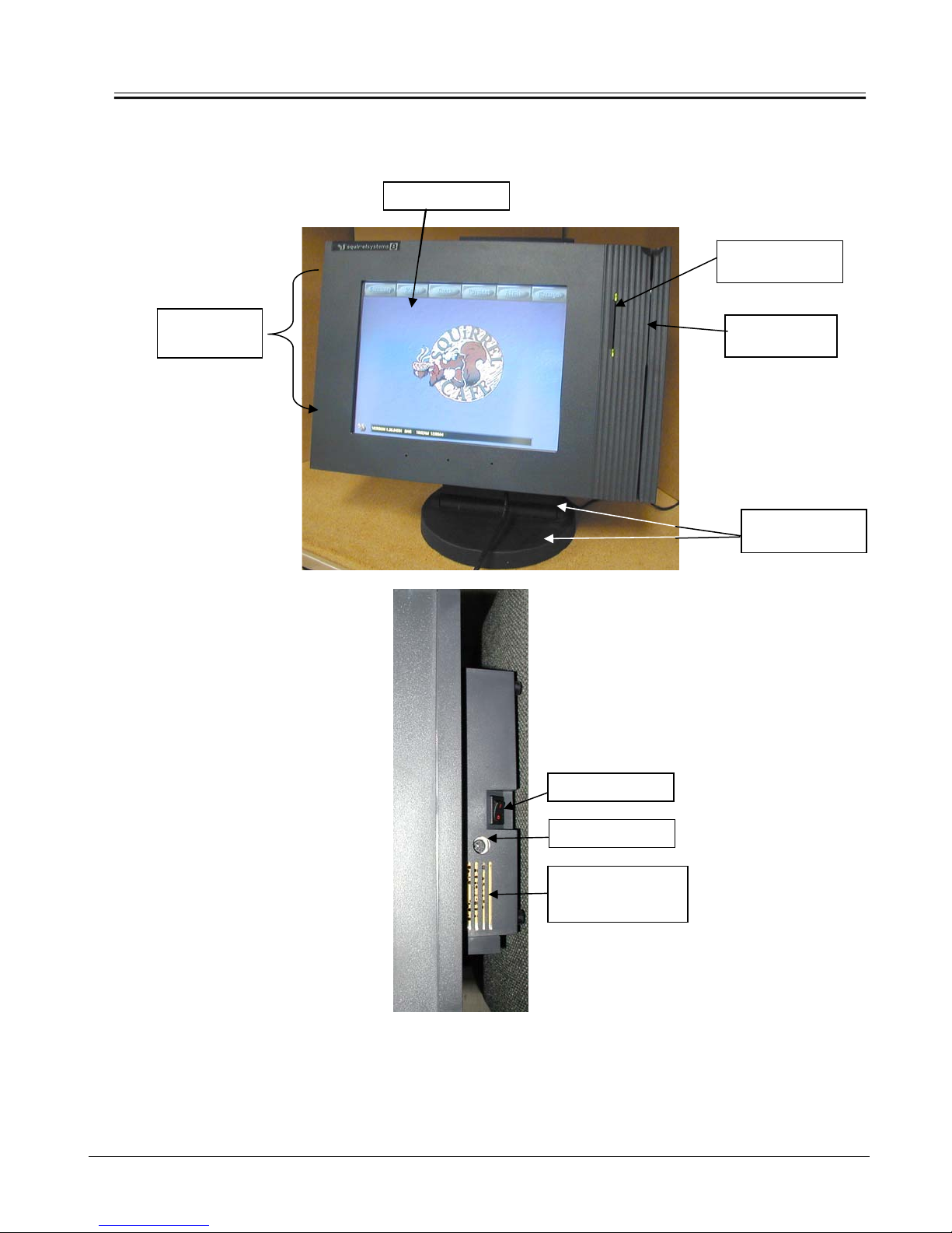
Product Description
Air Exhaust
Area
GENERAL INFORMATION
Touchscreen
Power Switch
Keyboard Port
Internal Intake
Fan Vents
Optical ID Reader
Badge Card Slot
Magswipe
Reader/Slot
Adjustable Stand
and Backplate
3/24/05 Preliminary Release 1-7
Page 14
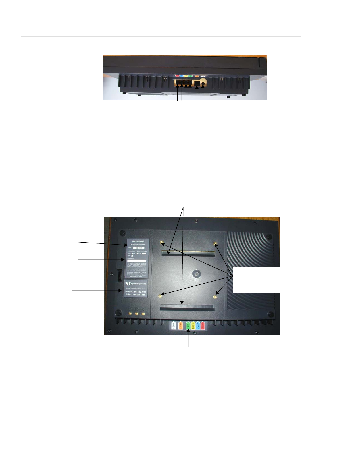
Serial Number
Label
Workstation’s Ethernet
MAC Address
Sales & Service
Label
GENERAL INFORMATION
6 5 4 3 2 1
1. Power Jack – AC/DC Power Supply Adaptor is connected here.
2. Ethernet Port – 10/100 Base – T/TX, RJ45 Jack for SquirrelOne Network
Connection.
3. COM 4 – RJ12 Interface Jack configured for default Customer Display
Tower.
4. Cashdrawer Port – RJ12 Jack provides Dual Cashdrawer Output.
5. COM 2 – RJ12 Interface Jack configured for default POS printer.
6. COM 1 – RJ12 Interface Jack configured for default POS printer.
Refer to Appendix D for port signal pin assignment.
Wall Mounting Bracket Slots
Cable Location Label
Stand Back
Plate Mounting
Holes
1-8 Preliminary Release 3/24/05
Page 15

DISASSEMBLY AND ASSEMBLY
CHAPTER 2: DISASSEMBLY AND ASSEMBLY
General Servicing Precautions
The following are general precautions that should be taken by technicians when
servicing the Workstation 8 product. Please refer to APPENDICES at the back of
the manual for a detailed explanation.
• A safe EDS protected work area is required to service the
Workstation 8 product to prevent damage to sensitive
components from static discharge. Refer to APPENDIX A.
• Extra care needs to be exercised when handling and cleaning
the LCD to prevent any damage. Refer to APPENDIX B.
• Circuit boards need to be handled and stored with care to
prevent any ESD damage. Refer to APPENDIX C.
• Opening & Closing – all cabling needs to be arranged so that
they will not be pinched or interfere when you open and close
the workstation case for servicing.
Service Equipment and Parts List
The following equipment is required to service the WORKSTATION 8 according
to this manual:
• Anti-static mat with ground-wire and wrist strap – safe ESD work
area
• Side cutters
• #1 and #2 Phillips screwdrivers
• Multimeter
• Magnetic head cleaning card (SQ-2940 pkg of 10
pkg of 50)
• Scissors
Disassembly Instructions
When disassembling the workstation make sure the workstation is turned off and
disconnected from all cabling and peripherals.
OR SQ-2941
3/24/05 R1.0 Preliminary Release 2-1
Page 16
DISASSEMBLY AND ASSEMBLY
Reassembly Instructions
Reassembling is the reverse of the disassembly process. Use care to ensure
that all cables and screws are returned to their proper positions. Check that no
loose parts have been left inside and everything is properly installed and
tightened.
A list of modules and/or their sub-assemblies:
Module / Sub-Assembly
Workstation 8 for SquirrelOne with Power Supply and
Stand
Workstation 8 for SquirrelOne with Power Supply and no
Stand
Workstation 8 for SquirrelOne without Power Supply and
Stand
AC / DC Power Supply (no AC cable)
AC Power Supply Cord
Touchscreen Overlay/Sensor
LCD Assembly (LQ121S1DG41 LCD) & Shield Top
Note: Primarily for field servicing
ISIS Badge Reader Kit
Magswipe Reader
Part Number
SQ-2020
SQ-2021
92-800
31-038
78-010
SQ-2523
92-241
SQ-2899C
SQ-2902
Motherboard – SBC
Comes with 64M RAM
Table 2.1 Module / Sub-Assembly Parts List
2-2 Preliminary Release 3/24/05
SQ-6593
Page 17

DISASSEMBLY AND ASSEMBLY
Various cables, screws and miscellaneous parts
Part Description Part Number
Cable RJ12 to RJ12 Interface
Use: COM1
COM2
COM4
Cable CATS Ethernet Patch
Use: SquirrelOne
Cable RJ12 to RJ45 Printer Interface
Use: COM2
Cable Cash Drawer
Use: DRW
Dual Cash Drawer Adaptor
Plastic Split Tubing (per foot)
#6-32 X 1” Pan Head Phillips Screw
Front to back housing
#4 Star Washer
For LCD mounting and motherboard
Screw #4-40 x ¼
- LCD to mounting bracket
- Motherboard to rear shield
- Inverter to LCD mounting bracket
SQ-7035
SQ-7706
SQ-7345
SQ-7175
95-026
77-040
82-009
83-003
82-004
Screw #4 x ¼
For card guide rails
Screw #4 x 3/8
To secure magswipe reader
Display Backplate
Rear Internal Shield
LCD Data Cable
LCD Back Light Cable
82-068
82-067
89-540
89-541
76-245
76-208
Table 2.2 Miscellaneous Parts List
3/24/05 Preliminary Release 2-3
Page 18
DISASSEMBLY AND ASSEMBLY
Power Switch
74-020
Power Switch Cable
Plastic Card Guide
Black Cable Tie
Fan
ISIS Cable
Adjustable Stand with Weight Assy
Base
Back Plate
Wall Mount Bracket
Rear Workstation 8 Plastic Housing
Top Workstation 8 Plastic Cover
WS8 High Touch Strip
ISIS Badge Rdr Kit
76-338
99-608
86-015
91-070
76-301
92-205
92-195
99-604
92-207
99-618
99-622
99-623
SQ-2899C
#6-32x1/2” Phil Black Screw
For Fan to Rear Shield
82-608
Table 2.2 Miscellaneous Parts List
2-4 Preliminary Release 3/24/05
Page 19
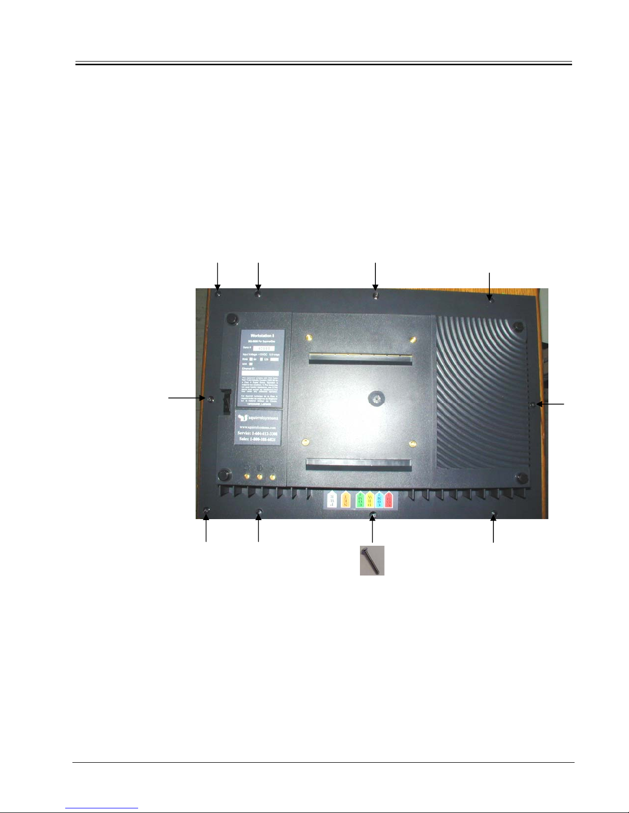
DISASSEMBLY AND ASSEMBLY
Removing the Front
Cover
To remove the Front Cover:
This procedure requires a #2 Phillips screwdriver.
1. Place the WORKSTATION 8’s front of the unit face down on the
anti-static mat. Ensure that the mat is clean of debris that could
scratch or damage the workstation.
2. Remove all 10 screws that secure the front cover to the bottom
housing as shown in the picture below.
3. Carefully hold the front and rear housing together and turn the
unit over right side up.
4. Carefully lift off the front cover to expose the internal
assemblies.
3/24/05 Preliminary Release 2-5
Page 20
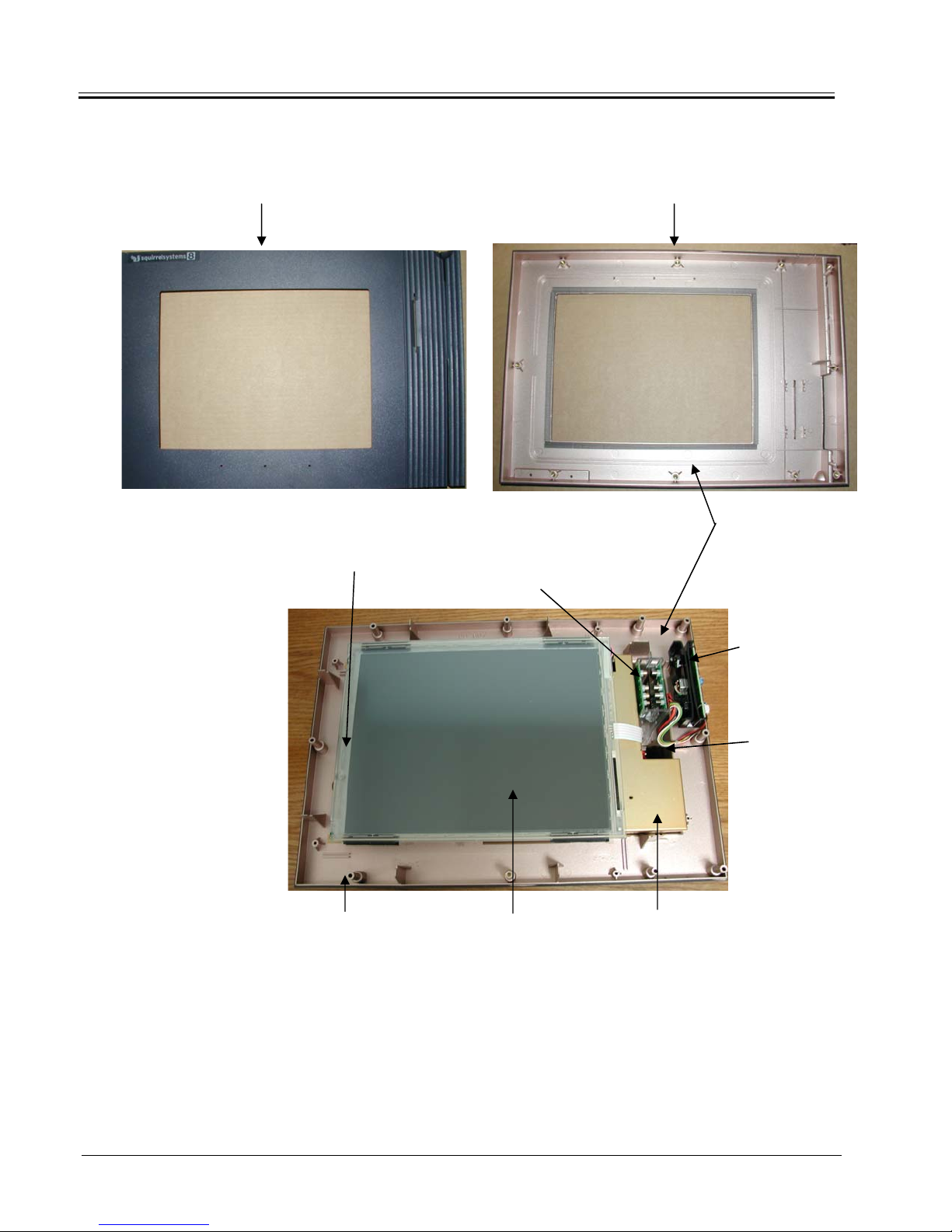
DISASSEMBLY AND ASSEMBLY
Front/Top Cover Front/Top Cover
Front View Back View
LCD Optical ID Reader
(Isis Badge Reader)
Base Bottom Housing Sensor/Overlay LCD Mounting
Bracket
Spray coated with
copper loaded paint for
EMI/RFI shielding
Magswipe
Reader
Power Switch
2-6 Preliminary Release 3/24/05
Page 21
DISASSEMBLY AND ASSEMBLY
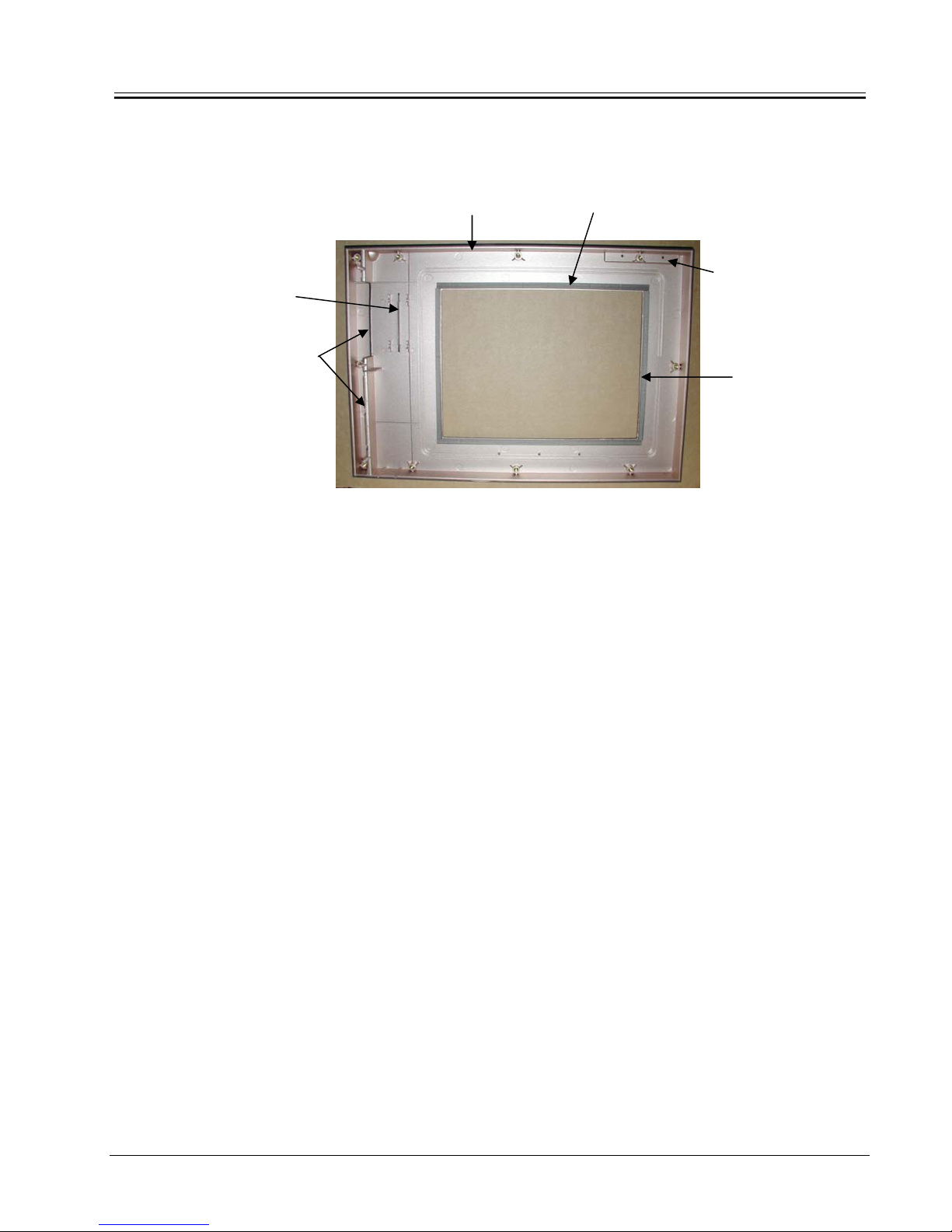
(
)
Replacing the Front
Cover
Badge Card Slot
Magswipe Card Slot
In the event the top cover is damaged and is required to be replaced, it should
be noted that the top cover consists of the following: Top cover plastic, RF
Gasket Strips and the Touch Strip located in front of the cover.
Front/Top Plastic Cover 10.25” RF Gasket Strip (2 pcs)
(99-622) (88-053-1)
Touch strip
(on front side)
(99-623)
7.35” RF Gasket Strip
(2 pcs)
88-053-2
Backside View
When ordering, all 3 items need to be ordered at the same time. The gasket
and Touch Strip are not reusable. When installing the gasket, DO NOT stretch
the gasket during application.
Reassembling the top cover to the bottom housing is the reverse of the
disassembly process. When the top cover is fitted over the bottom housing,
make sure the Badge Reader’s Card Guides fit into place in the Badge Card
Slot located in the Font Cover.
Removing the
Magswipe Reader
1. To remove the Magswipe Reader a #1 Phillips screwdriver is
required.
2. When disconnecting the interface cable from the ISIS
Detector board, attention should be paid as to how the
connector is oriented and connected to the right angle
connector on the detector board.
3/24/05 Preliminary Release 2-7
Page 22
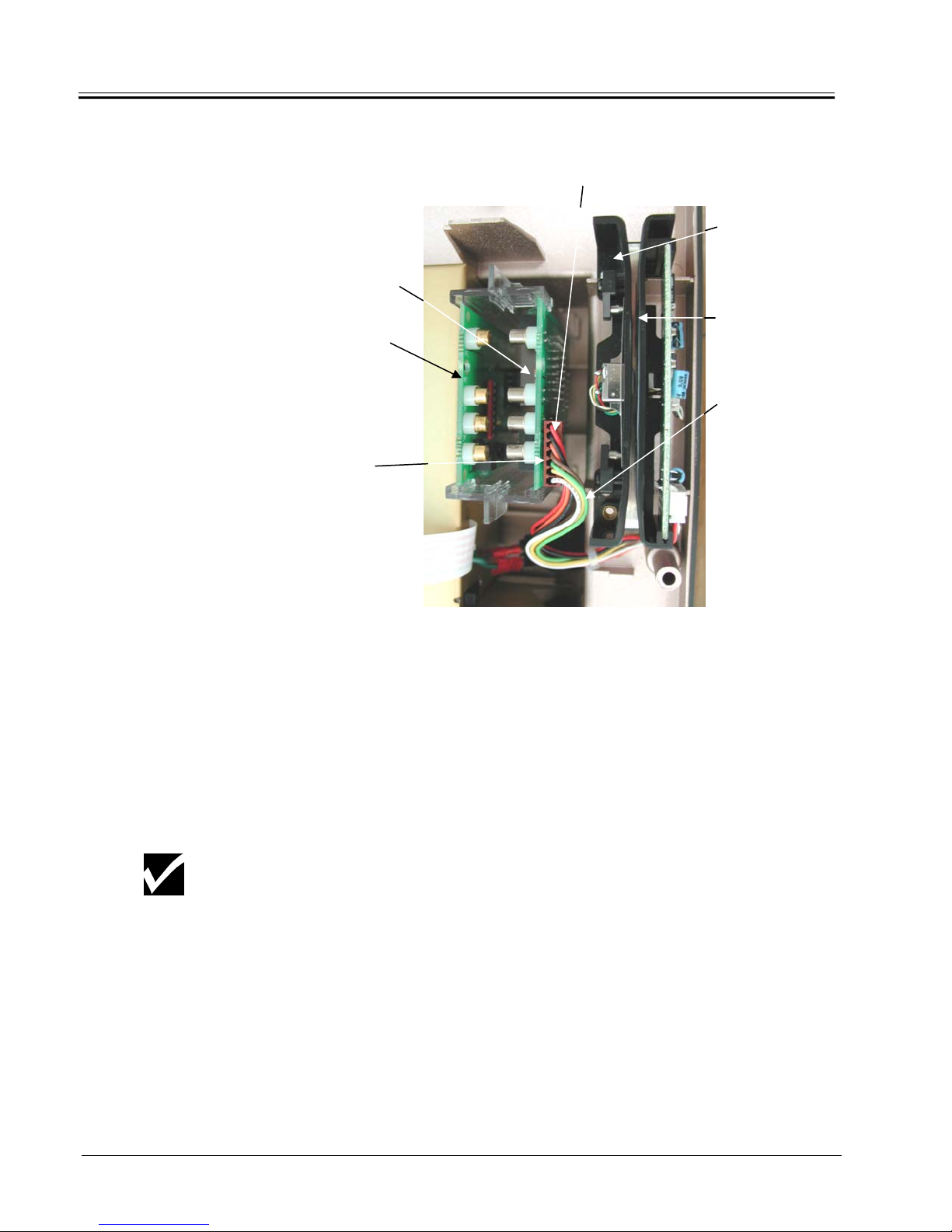
DISASSEMBLY AND ASSEMBLY
ISIS Detector PCB
ISIS Emitter PCB
2. Disconnect
Red Wire
1. Remove Screw
Magswipe Reader
Interface Cable
Removing the ISIS
Badge Reader
(Optical Reader)
NOTE
1. Without touching the emitter (emitting diode) and detector
(phototransistor) components (these will either be gold or
silver), carefully grasp the top edges of the emitter and
detector boards and gently slide them (together) upwards
and out of the card guides.
Care should be taken when handling these boards as the emitter &
detector components have been aligned for optimal performance.
Accidentally shifting these components can cause the reader to not read
the badge cards.
2-8 Preliminary Release 3/24/05
Page 23
DISASSEMBLY AND ASSEMBLY
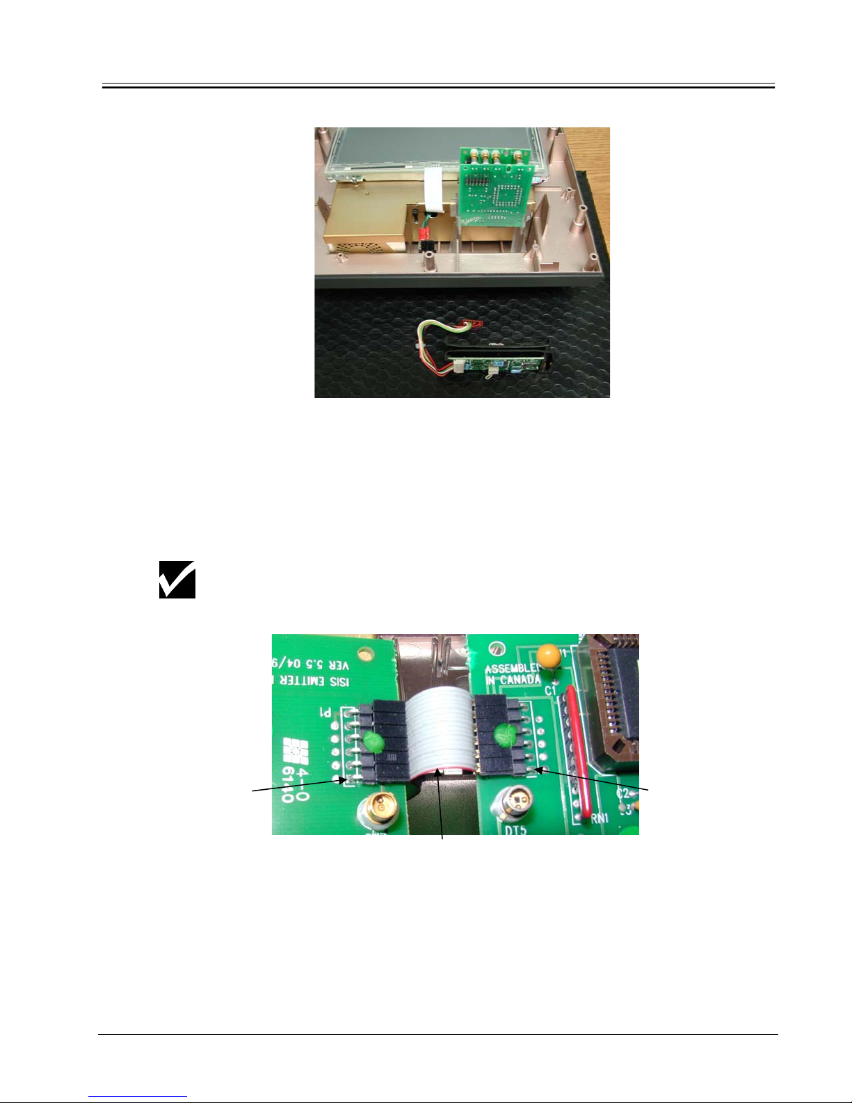
Removing the ISIS Reader
NOTE
2. Both the detector & emitter boards need to be disconnected
from the ribbon cable. Always handle these boards by
holding their edges and avoiding touching the components
and circuitry.
The ribbon cable can only be disconnected from the Motherboard after the
LCD Mounting Bracket is disassembled from the Internal Shield Housing.
Pin 1
Red wire
Pin 1
Replacing these boards is the reverse of removing and care should be
exercised when reconnecting and reinserting into the card guides. The
red wire of the ribbon cable connects to Pin 1 on both P1 connectors of
both boards. Both cards need to be slid down the card guide rails
completely and should be seated properly.
3/24/05 Preliminary Release 2-9
Page 24
DISASSEMBLY AND ASSEMBLY
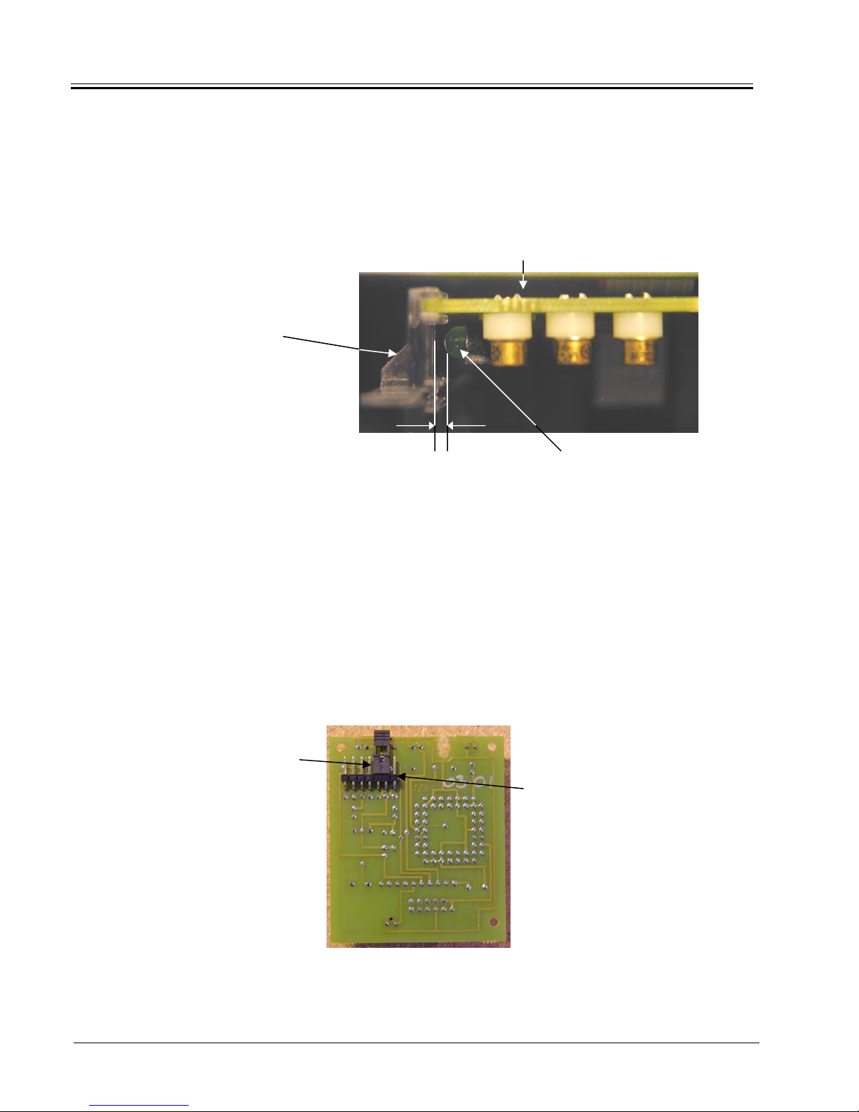
3. Ensure that each green LED on the ISIS Badge Reader
PCBs are properly aligned with the card guide lightpipes as
shown below. The LED should not touch the card guide but
should be about 1/16” (1 mm) away.
Card
Guide/Lightpipe
1/16” Green LED
(1 mm)
ISIS PCB
Badge Reader LEDs
If the LED is not properly positioned or the lightpipe is dim and uneven the LED
can be carefully bent into a better position, ensuring that the LED does not
touch the card guide.
In the event the workstation being serviced does not have a Magswipe
Reader, the ISIS detector board will have a jumper installed on the right angle
connector located at the back of the board as shown below.
Jumper
Pin 1
ISIS Detector PCB
2-10 Preliminary Release 3/24/05
Detector PCB Jumper Setting
Page 25

DISASSEMBLY AND ASSEMBLY
Removing the ‘DG41
LCD Assembly
(Mounting Bracket)
from the Rear Internal
Shield Assembly
The ‘DG41 LCD Panel requires an Open Frame Inverter
(DMA23058) which is mounted to the backside of the LCD
NOTE
Mounting Bracket.
The LCD Mounting Bracket is merely resting on top (acting as a lid)
of the Rear Internal Shield Assembly. No tools are required when
removing the LCD Mounting Bracket from the Rear Internal Shield
Assembly.
1. Carefully lift off the LCD Mounting Bracket a few inches, as
there is the Touchscreen Sensor Cable, Backlight Cable and
LCD Data Cable attached to the Motherboard.
Carefully lift off
the LCD
Mounting Bracket
a few inches
3/24/05 Preliminary Release 2-11
Page 26

DISASSEMBLY AND ASSEMBLY
2. Disconnect the Touchscreen Sensor Cable, Backlight Cable
and LCD Data Cable from the Motherboard and lift the LCD
Mounting Bracket clear away from the Rear Internal Shield
Assembly.
Backlight Cable
LCD Data Cable
D
Touchscreen
Sensor Cable
After the LCD Mounting Bracket has been completely removed, the ISIS
NOTE
cable can now be disconnected from the Motherboard.
When disconnecting the cables, attention should be paid as to how the
cables are connected to the Motherboard and the orientation of the cables’
NOTE
connectors. When disconnecting cables,
Remove/disconnect the cables by pulling on their connector or pull-tab.
Reassembling the LCD Mounting Bracket to the Rear Internal Shield Assembly
is the reverse of the disassembly process. A visual inspection should be done
after to make sure the LCD Mounting Bracket is resting properly (on all sides)
on top of the Rear Shield Assembly.
Top View of LCD Mounting Bracket
DO NOT PULL on the cable itself.
Rear View of LCD Mounting Bracket
2-12 Preliminary Release 3/24/05
Page 27

NOTE
DISASSEMBLY AND ASSEMBLY
Make sure the Touch-screen cable tail is positioned properly in
between the notch of the rear metal casing before resting the LCD
Mounting Bracket on top of the casing. The Touch-screen cable tail
should also be bent with a radius as it is channeled through the
notch and should move freely through the notch.
Disassembly of the
‘DG41 LCD Assembly
Removing the Touch Screen Sensor (Overlay)
To disassemble the LCD assembly a #1 Philips screwdriver and
side cutters are required
.
The LCD panel is very sensitive to pressure and can be damaged.
Keep dirt and debris away from the LCD panel. Refer to
APPENDIX B on Handling the LCD.
1. Carefully hold the side edge of the sensor where the flat flex
cable is and lift off slowly to disengage the Velcro. Then
disengage the Velcro from the other side of the sensor/LCD.
2. Handle the touchscreen with reasonable care when not
integrated onto the LCD.
3. DO NOT PULL OR STRESS THE FLAT FLEX CABLE.
Refer to APPENDIX E for Cleaning & Specifications.
3/24/05 Preliminary Release 2-13
Page 28

DISASSEMBLY AND ASSEMBLY
Reassembling/Replacing the Touch Screen Sensor (Overlay)
Before mounting the Touchscreen Sensor, the face of the LCD display must
be clean of any dust or debris. Refer to APPENDIX B LCD Handling. The
backside of the Touchscreen Sensor must also be cleaned of any fingerprints.
Refer to APPENDIX E Touchscreen Sensor. The space between the
Touchscreen Sensor and the LCD face must be clean and free of any foreign
objects.
The Touchscreen Sensor is secured to the LCD via a 3M Hook and Loop
product (Velcro). Tiny, stiff hooks mesh with pliable loops for quick secure
fastening. 4 pieces of this tape are applied, 2 to the top edge and 2 to the
bottom edge of the backside of the Touchscreen Sensor. The adhesive tape
is set back slightly from the edge of the active area of the Touchscreen. When
the Top Plastic cover is reassembled, the mounting tape should not be visible.
When mounting the Touchscreen Sensor to the LCD, the Active Area Border
of the Touchscreen Sensor must be aligned to the LCD’s Display Area Border.
Once positioned, gently press the Touchscreen firmly against the LCD.
Removing the ‘DG41 LCD from the LCD Mounting Bracket
1. Make sure the ESD protected work area has no debris on the
antistatic mat.
2. Turn the LCD Mounting Bracket over and place the assembly face
down on the antistatic mat.
3. Cut the cable tie that is securing the backlight cable (cable tail from
LCD) to the cable tie mount.
Exercise care not to scratch the LCD’s display surface. Refer to APPENDIX B
LCD Handling.
NOTE
4. Disconnect the backlight cable from the Open Frame Inverter’s
interface connectors.
5. Cut the cable tie that is securing the LCD Data Cable to the tie
mount.
6. Carefully pull back the RF Gasket just enough to loosen the
adhesive (do not completely remove) so that the LCD Data Cable
can be passed through later.
When disconnecting cables,
Remove/disconnect the cables by pulling on their connector or pull-tab.
NOTE
2-14 Preliminary Release 3/24/05
DO NOT PULL on the cable itself.
Page 29

4. Disconnect the
Backlight Cable
DISASSEMBLY AND ASSEMBLY
3. Cut cable tie securing backlight cable
5. Cut the cable tie
that is securing the
LCD Data Cable
6. Carefully pull
back the RF
Gasket (do not
completely
remove).
7. Carefully turn the LCD Mounting Bracket over, right side up.
NOTE
Be careful not to touch the LCD’s display surface when turning the LCD
Mounting Bracket over.
8. Using a Phillips #1 screwdriver remove the 4 screws and
washers that secure the LCD to the LCD Mounting Bracket.
#4-40x1/4 Screw
#4 Star
Washer
9. Carefully lift off the LCD at the same time slowly passing the
backlight cable and the LCD data cable through the cutouts
in the LCD Mounting Bracket.
3/24/05 Preliminary Release 2-15
Page 30

DISASSEMBLY AND ASSEMBLY
Disconnecting the LCD Data Cable
When disconnecting the LCD data cable from the LCD connector, attention
should be paid to how the data cable is oriented and connected to the LCD
NOTE
connector.
Removing the Open Frame Inverter
83-006
#6 NYLON WASHER
Turn the LCD Mounting Bracket over. Using a #1 Phillips screwdriver
unscrew the 2 screws securing the Inverter to the LCD Mounting
Bracket.
82-004
#4-40x1/4 Screw
32-017
Inverter – DMA23058
82-004
#4-40 x 1/4 SCREW
WARNING
Shock hazard
if powered!
76-208
Backlight Cable
Refer to Appendix I for LCD bracket preparation for the mounting of the
LQ121S1DG41 display.
NOTE
2-16 Preliminary Release 3/24/05
Page 31

DISASSEMBLY AND ASSEMBLY
Reassembly
Reassembly is almost the opposite process of disassembly.
1. Make sure the LCD Data Cable is connected in the proper orientation to
the LCD and Torque Seal has been applied to either side of the data
cable connector.
Use the following method when connecting the LCD data cable to the
LCD.
A) Correct connection
ispersedStress is d
Base (horizontal film base) is required
B) Incorrect connection
Stress is dispersed
Base (horizontal film base) is required
2. When mounting the LCD, carefully pass the backlight cables and the
LCD data cable through the openings in the LCD Mounting Bracket.
3. Line up the LCD’s Mounting Holes to the stand-offs.
4. Install the washers and the screws. Do not over tighten the screws at
this point.
3/24/05 Preliminary Release 2-17
Page 32

DISASSEMBLY AND ASSEMBLY
5. Adjust and position the LCD, then tighten the screws using a
crisscross pattern. DO NOT USE POWER TOOLS, ONLY HAND
TIGHTEN THE MOUNTING SCREWS.
Binding Torque Value: 0.196N x m (2.0Kgf x cm)
NOTE
6. The pink and blue wires of the LCD’s backlight cable connect to Pin
1 of interface connectors J2 & J3 on the Inverter Board.
Base Bottom Disassembly
Disconnecting the Power Switch Cable from the Motherboard
1. Disconnect the power switch cable from the quick tabs located on
the motherboard.
2. Cut the cable tie strap securing the ferrite bead to the Rear Internal
Shield Casing.
1. Disconnect the power
switch cable from the
quick tabs.
When disconnecting cables, DO NOT PULL on the cable itself.
Remove/disconnect the cables by pulling on their connector or pull-
NOTE
tab.
2. Cut the cable
tie strap securing
the ferrite bead
3. Pull back the power switch cable until the cable is clear of the
slot/channel on the Rear Internal Shield Casing.
Attention needs to be paid as to how the power switch cable was
routed and how the ferrite bead was positioned when secured to
NOTE
2-18 Preliminary Release 3/24/05
the Rear Internal Shield Casing.
Page 33

Reassembly
Reassembly is the reverse of the disassembly process.
Disassembly of the Internal Shield Assembly
Removing the Internal Shield Assembly out of the Base Bottom Plastics
1. The Internal Shield Assembly sits inside the Base Bottom Plastic
Housing and is not secured to the Bottom Plastic Housing in any way.
To remove the Internal Shield Assembly, grasp the assembly as shown
in the picture below and carefully lift the assembly straight out of the
base bottom evenly.
DISASSEMBLY AND ASSEMBLY
Reassembly
Reassembly is the reverse of the disassembly process. Simply align the
Internal Shield Assembly to the Base Bottom Housing and carefully lower
the Internal Shield Assembly into the Base Bottom Housing. Check to make
sure the Internal Shield Housing is sitting evenly inside the Base Bottom
Housing.
Removing the Power Switch Cable and the Power Switch
1. Disconnect the power switch cable from the tabs of the power switch.
When disconnecting cables, DO NOT PULL on the cable itself.
Remove/disconnect the cables by pulling on their connector or pull-tab.
NOTE
3/24/05 Preliminary Release 2-19
Page 34

DISASSEMBLY AND ASSEMBLY
2. Gently push the switch through the Base Bottom Housing until the
switch pops out.
Reassembly
Reassembly is the reverse of the disassembly process.
Removing the Intake Fan
1. Disconnect the fan’s 3-pin connector plug from the 3-pin header
(Reference Designator: CN2) on the motherboard.
2. The fan is secured via two #6-32x1/2” Phil screws (as depicted below)
onto PEM Head Standoffs located inside the Shield Housing. To remove
the fan use a #1 Phillips screw driver and carefully unscrew the top screw
first followed by the remaining screw.
82-608
6-32x1\2” Phil Screw (x2) Black
Located on top corner (unscrew first)
& bottom corner (unscrew last)
CN2
FAN ASSEMBLY
2-20 Preliminary Release 3/24/05
Page 35

Reassembly
Reassembly is the reverse of the disassembly process.
Make sure the cable tail from the fan is of the correct length. If not then any
excess cable needs to be bunched neatly together and cable tied to achieve
NOTE
the proper cable length.
Removing the Motherboard from the Internal Shield Housing
1. Using a Phillips #1 screwdriver, remove the 9 screws and
washers that secure the motherboard to the Internal Shield
Casing.
DISASSEMBLY AND ASSEMBLY
2. Removing the motherboard out of the Rear Shield Housing should
be done with care and without any stress to the board. To remove
the motherboard, carefully lift the end of the motherboard where the
hard drive mounting area (Reference Designator: HD1) is located.
This will cause the board to come up at an angle. Once the board
has cleared the Rear Metal Casing’s wall, slide the board
completely out carefully. Care should be taken not to damage the
foil tape located on the inside wall of the metal casing near the
fan/keyboard area.
3/24/05 Preliminary Release 2-21
Page 36

DISASSEMBLY AND ASSEMBLY
Reassembly
Reassembly of the same motherboard in the Shield Housing is the reverse
of the disassembly process.
1. Inserting the motherboard into the Rear Shield Housing should be
done with care and without any stress to the board.
2. When reassembling, angle the motherboard so that the
keyboard/fan end of the board goes in first. Gently lower the board
down when in position.
3. Once the board is sitting inside the casing, shift the board around to
make sure there is some play to ensure proper placement. Check
front side of the metal casing’s area where the I/O connectors are
exposed to make sure the I/O connectors are properly aligned with
the metal casing’s I/O connector openings. Also check that the
keyboard connector is aligned properly to the metal casing’s
opening before securing board down.
NOTE
4. Install screws and washers to secure the motherboard to the shield
casing.
Screws have two purposes: one, to secure the motherboard into
place, particularly around I/O areas where user interaction causes
NOTE
additional stress; and two, the screws are the means of electrically
connecting the metal shield to the chassis ground source on the
motherboard. Be sure to use all screws.
Refer to APPENDIX F for the following:
• New Motherboard Preparation
NOTE
• Foil Taping the Rear Shield Casing
• Foil Tape Specifications
Refer to APPENDIX G for Motherboard Connector Descriptions, Jumper
Descriptions & Settings.
Resetting CMOS for Squirrel Defaults
The WS8 product now offers the feature where by resetting CMOS
to factory defaults will reset CMOS to Squirrel’s required Default
NOTE
Settings.
To reset CMOS:
2-22 Preliminary Release 3/24/05
Page 37

- Turn power on or re-boot system and press the “DEL” key on
the keyboard to access CMOS.
- When the CMOS main menu appears select “Load Optimized
Defaults” to load Squirrel’s Default Settings.
- Save settings and exit CMOS for changes to take effect.
Removing the Card Guide Rails
• Using a Phillips #1 screwdriver remove the two screws
(one on each Card Guide) securing the Card Guides to
the Base Bottom Plastics.
Reassembly
• Reassembly of the Card Guide Rails to the Base Bottom
Plastics is the reverse of the disassembly process.
DISASSEMBLY AND ASSEMBLY
• Make sure the Card Guides are properly in place before
securing the rails.
3/24/05 Preliminary Release 2-23
Page 38

CHAPTER 3: INSTALLATION
Installation of the SQUIRREL WORKSTATION 8 involves the
following recommendations:
• General guidelines
• Electrical Power Requirements
• Location and mounting positions
• Proper installation of the mounting hardware
• Host/Server Communication Protocol
• ISIS Badge Reader Configuration
• Cable Location Label - l/O Interface
• Typical Workstation & Peripheral Setup
INSTALLATION
General Guidelines
• Final testing of the installation
1. The Workstation should have sufficient clearance to allow
access to the power switch and cables.
2. Account for the Workstation’s dimensions when selecting an
installation location or enclosure. Refer to Chapter 1 for product
dimensions.
3. Workstation must be placed/mounted at a comfortable working
level and yet will not block traffic flow in the restaurant when in
use.
4. Consider locations for accessories such as AC power outlets
and lighting for installation and maintenance convenience.
5. Location should have adequate ventilation (2 inches) and
measures should be taken to avoid obstructing the airflow to
allow for maximum cooling. Note air intake and exhaust
locations – see page 1-7.
6. Location must allow for credit card reader swiping action and
7. Workstation should be located where the possibility of food or
3-1 R1.0 Preliminary Release 3/24/05
badge reader insertion.
beverage spillage is at a minimum risk.
Page 39

INSTALLATION
8. Workstation should be kept away from high heat sources such
as grills, fryers and heat lamps.
9. Location should have adequate space for the external power
supply; check printer and cash drawer installation. The external
power supply must have 1" clearance on all sides.
Electrical Power Requirements
The power line for the Workstation 8 must be kept in accordance
with the SQUIRREL POWER SPECIFICATION GUIDE. This
means the Workstation as well as all locally connected peripherals
will be plugged into a SQUIRREL Dedicated Isolated Ground
receptacle.
Location and Mounting Positions
The WORKSTATION 8 can be mounted in a variety of locations
and positions using the Tilt Stand or Wall Bracket as shown below.
The General Guidelines and Power Requirements mentioned
above must be taken into consideration during customer
consultation for the best locations and mounting methods.
SUSPENDED UNDER COUNTER MOUNT
3-2 Preliminary Release 3/24/05
Page 40

INSTALLATION
ANGLED WALL MOUNT SIDE WALL MOUNT
“TRADITIONAL”
COUNTER TOP
COUNTER SUNK
(Using Wall Bracket)
Proper Installation of the Mounting Hardware
Tilt Stand (92-205) Installation
The Tilt Stand can be used to suspend the Workstation 8 from a
shelf, rack, wall, or to support the Workstation on a countertop in a
traditional fashion.
By aligning the Workstation in different positions on the Back Plate
of the Tilt Stand, these options can be obtained.
When the Workstation 8 is mounted vertically on the Back Plate,
the Tilt Stand attaches as in Figure 3-1. The tubing and cables can
then be routed through the hole in the Back Plate.
FLUSH WALL MOUNT
(Using Wall Bracket)
3/24/05 Preliminary Release 3-3
Page 41

INSTALLATION
Tilt Stand
Back Plate
Figure 3-1. WORKSTATION 8 with Tilt Stand
Similarly, the Workstation 8 can be secured to the Back Plate
sideways except when attached from the left. Use only two screws
as shown in Figure 3-2.
Tilt Stand
Back Plate
Figure 3-2.Workstation 8 with Tilt Stand (Sideways from Left)
3-4 Preliminary Release 3/24/05
Page 42

INSTALLATION
For counter top mounting where the Tilt Stand is not to be screwed
to the countertop, a weight can be attached to the base of the Tilt
Stand as shown in Figure 3-3. The base weight is shipped
standard with the Workstation 8.
Figure 3-3. Tilt Stand with Weight
There are three screw holes for securing the base to the mounting
surface. It is important that the correct screws be used for the
surface where the base is being installed. Long wood screws
should be used for wood paneling and shelves and "butterfly shield"
screws MUST be used for a surface such as gyproc.
Ensure that wood screws are secured into wall studs when wall
mounting the Workstation. If they are not secured properly, then the
weight of the Workstation will cause the Workstation to pull out of
the wall and fall, causing damage to the restaurant’s wall and the
Workstation itself. A commercially available stud locator (available
at hardware stores) should be used during installation.
3/24/05 Preliminary Release 3-5
Page 43

INSTALLATION
Adj
usting the Tilt Stand
BASE
SCREWS
(3)
To adjust the angle of the Tilt Stand:
1. Remove the three base screws that secure the stand to the wall,
countertop or shelf if necessary. See Figure 3-5. The
Workstation may have to be removed in order to do this.
TILT STAND
BACK PLATE
BASE
Figure 3-5. Tilt Stand Base Screws.
2. Locate the three setscrews on the backside of the Tilt Stand
Base as shown in Figure 3-6.
3-6 Preliminary Release 3/24/05
Page 44

INSTALLATION
Set Screws (3)
(1/8” Allen key)
Figure 3-6. Tilt Stand Base Setscrews.
3. Using a 1/8" Allen Key, loosen these screws just enough so that
the back-plate of the stand begins to move. While holding the
stand against the mounting surface, adjust the back-plate to the
angle desired. On a piece of masking tape placed on the raised
portion of the base by the back-plate, mark the desired backplate angle with a felt pen. The back-plate angle can now be set
by tightening the setscrews using the mark on the tape as a
guide for the desired angle. (Don't forget to remove the tape
afterwards.)
4. If needed, the tilt angle range can be switched over to the
opposite side of the base. Remove the setscrews and lift the
back from the base. Flip the back 180° and re-install it into the
base. Replace the washers, adjust the back to the desired angle
and tighten the setscrews.
5. Place the stand in its previous location and fasten the base
screws.
6. Install/mount the Workstation 8.
3/24/05 Preliminary Release 3-7
Page 45

INSTALLATION
g
)
Mountin
the Workstation 8 to a Wall Bracket (92-207
The Wall Bracket can be used in two ways: to attach the
Workstation to a wall, or to provide a slight tilt for a flush countermount installation.
WALL MOUNT
Mounting screws MUST be secured into the wall stud. (Two
screws are sufficient for vertical studs.) “Butterfly Shield screws”
must be used for gyproc to ensure that the bracket doesn’t pull
away from the wall causing the Workstation to fall.
See Appendix H for the use of “Butterfly shield” type screw.
Mounting flanges on the Wall Bracket hold and support the
Workstation. A foam insert is included as a spacer to prevent
unintended dislodging of the WS from the bracket, while still
allowing easy service access. Place the Workstation on the
bracket as shown in Figure 3-7.
Foam Insert
(“Bump-off”
Preventer)
Foam Insert
#98-302
#98-302
Figure 3-7. Wall Mount
The rubber feet on the backside of the Workstation may have to be
removed for it to be wall mounted.
3-8 Preliminary Release 3/24/05
Page 46

INSTALLATION
COUNTER SUNK MOUNT
The Wall Bracket can be attached to the back of the Workstation to
provide a slight tilt when the unit is mounted on a counter top.
The four mounting screws used to secure the Workstation 8 to the
Tilt Stand can be used to attach the Wall Bracket to the Workstation
as shown in Figure 3-8.
Figure 3-8. Attaching the Wall Bracket to the Workstation 8.
Host/Server Communication Protocol
The standard communication protocol between the Host/Server and
the WS8 product is Ethernet 10/100 Base-T. TCP/IP (Transfer
Control Protocol/Internet Protocol) is the standard used for
SquirrelOne (POS) to communicate between Host/Server and
workstation.
3/24/05 Preliminary Release 3-9
Page 47

INSTALLATION
–
ISIS Badge Reader Configuration
The ISIS badge reader can be configured for the type of ISIS
Badge Card series used. Series 1 was the original badge type.
Series 2 was developed to extend the range of ID numbers. See
STN 073 for more detailed information.
To configure the series type:
1. Power on the workstation and load SquirrelOne software.
2. Once POS is loaded and the Workstation has initialized,
insert the badge card of the desired series.
3. The badge reader will automatically configure itself to the
series of badge card inserted after power-on.
Cable Location Label
4. To reconfigure the badge reader to a different series type,
power off the Workstation and perform steps 1 to 2 again.
I/O Interface
The Cable Location Label is located right above the Multi RJ12-I/O
connector, RJ45 Ethernet connector and Power Jack.
Refer to Chapter 1 “Product Description” for I/O Connector
description.
3-10 Preliminary Release 3/24/05
Page 48

INSTALLATION
Multi I/O Connector Label
The color scheme on the Cable Location Label developed for
earlier Squirrel Workstation models for each port/connector
descriptor still holds for the WS8 product. This color scheme was
introduced to aid in connecting peripherals to their respective I/O
port connectors. Interface cables used to connect the peripherals
to their respective ports and communication cables also have
corresponding matching color bands.
3/24/05 Preliminary Release 3-11
Page 49

INSTALLATION
y
r
r
y
pical Workstation & Peripheral Setup
T
Matching Color
Band
SQ-7035
Note: depending on
peripheral, COM port can
be configured to support
the following:
Printer
OR
Tower
OR
Weigh Scale
OR
Bar Code Reader
Printer
SQ-7035
SQ-7175
Cash Drawe
SQ-7035
Tower
OR
Weigh Scale
OR
Bar Code Rd
SQ-7706
Power Suppl
Ethernet Patch Cable
The power connector is friction lock. To prevent the plug from
becoming dislodged, attach tie wrap and loop cord to secure.
3-12 Preliminary Release 3/24/05
Page 50

INSTALLATION
g
All interface cables EXCEPT the Power Supply connection can be
made while the Workstation is powered on. Hence any
communication cables can be replaced without powering down the
Workstation.
Final Testin
Powering It On
of the Installation
Once the power, ethernet and peripherals have been interfaced to
the Workstation, it is now ready to be powered on. The Workstation
8 can be powered on without having the Squirrel POS software
activated on the host.
To power on the Workstation 8 while Squirrel POS is active:
1. Ensure that power and Ethernet communication lines to the host
are connected.
2. Turn the power switch ON.
3. On power up, the screen will go white for a few seconds and the
ISIS Badge Reader LEDs will also turn on. The following chain
of events will take place:
o POST (Power On Self Test)
o Will get IP Address
o Will load Linux Image – Spinning Wheel
o POS will load
LOADING DATA PAGE 0
LOADING IMAGE 1
o POS session will start.
For SquirrelOne software initially the Workstation will look for the
server.
4. If the POS program is active on the Host Server, the
Workstation should now load PROGRAM and DATA pages
automatically. If the POS program in not active, then select the
START BUSINESS DAY option within the Squirrel program on
the Host Server. Consult the software manuals for further
information on host to terminal operations.
3/24/05 Preliminary Release 3-13
Page 51

INSTALLATION
5. Once POS is loaded onto the Workstation and the Workstation
has initialized, insert a badge card into the Badge Reader to
configure the reader for the type of badge series to be used.
Screen Contrast
The Workstation 8 is designed so that the screen contrast is preset
to the maximum setting and thus eliminating the need for contrast
control.
Volume Control
The Workstation 8 is designed so that the volume control is also
preset to the maximum setting and thus eliminating the need for
volume control.
3-14 Preliminary Release 3/24/05
Page 52

CHAPTER 4: MAINTENANCE
There is relatively little general maintenance for the SQUIRREL
WORKSTATION 8, but disregarding maintenance will result in long
term problems for the user.
Caring for the WORKSTATION 8
The WORKSTATION 8 and its associated cables and peripherals
should not be immersed in liquids. The risk of liquids spilling on or
around the Workstation should be prevented. The WORKSTATION
8 is designed to be water-resistant, NOT waterproof.
The WORKSTATION 8 should be kept away from high heat
sources such as grills, fryers and heat lamps. Any area that is too
hot for prolonged exposure of your hand (more than a minute) is
too hot for the Workstation.
MAINTENANCE
General Cleaning
Cleaning solvents such as gasoline, turpentine and alcohol also
should NOT be used on the Workstation.
Routine cleaning can be performed by wiping the WORKSTATION
8 with a clean, soft damp cloth to remove dust and minor stains.
Soap and warm water can be used carefully with a rag to clean
stains. Make certain that the Workstation is powered OFF and that
NO water can drip from the cloth into the openings of the
Workstation. The touch-screen display can be cleaned with a
common household glass cleaner applied with a clean, soft cloth.
Examine the screen area, especially the gaps on the border of the
screen between the touch-screen surface and the plastic housing.
Carefully clean out any crumbs or other debris that could be
“touching” the screen. (An employee badge can be carefully used
to clean out the screen border areas.)
Exhaust vent and fan intake vents must be kept clean of dust
buildup. Clumps of dirt or ‘dust bunnies’ can block airflow and
restricted airflow causes overheating inside your Workstation.
When components overheat, they become stressed and eventually
fail. Overheating caused by dust is the primary cause of equipment
failure over time.
4-1 R1.0 Preliminary Release 3/24/05
Page 53

MAINTENANCE
Cleaning the Credit Card Reader
Regular use of the Credit Card Reader results in a residue buildup
on the magnetic head within the reader. This degrades
performance and will lead to the eventual failure of the credit card
reader. Regular cleaning of the reader will prevent this problem
from occurring.
Disposable cleaning cards are available from SQUIRREL for
cleaning the Credit Card Reader. A card should be used to clean
the reader every 2 - 4 weeks depending on usage. If the credit card
reader performance starts to degrade (i.e. credit cards take several
swipes to read) the reader should be cleaned.
To use the disposable cleaning card, simply follow the directions
that accompany it.
4-2 Preliminary Release 3/24/05
Page 54

CHAPTER 5: TROUBLESHOOTING
If the WORKSTATION 8 is required to be serviced on site (restaurant), it is
advisable that the service technician bring along a fully functional Workstation
in the event that the Workstation in question requires more than a simple
service. Swapping Workstations should be carried out in order to minimize
disruption to the site.
Troubleshooting on Workstations can be carried out using the Diagnostic
feature available in the SquirrelOne POS software. Reference can be made to
the V1.3x Functions document or the V1.3x Managers Guide for detailed
information regarding the Diagnostic feature.
The Workstation 8 has thus far proven to be a very reliable product. However,
there is always a chance that you may experience some problems. Listed
below are some common problems and possible solutions.
TROUBLESHOOTING
Problem Possible Solutions
Workstation is ‘ON’ but the screen is
blank/dark.
No touch in some areas of the screen
and recalibration doesn’t fix the
problem.
Touch the screen or insert a badge
card to activate the backlight. If there
hasn’t been any activity on the
Workstation for approximately 2
minutes, the software turns off the
backlight to conserve power.
Check to make sure the touch-screen
sensor is connected properly to the
motherboard.
Connect another touch-screen sensor
to see if the problem is rectified.
Component failure in the touch-screen
sensor circuitry on the motherboard.
Send unit to Repair Depot for
servicing/replacement.
5-1 R1.0 Preliminary Release 3/24/05
Page 55

TROUBLESHOOTING
Problem Possible Solutions
Badge Reader will not read Badge
Cards.
Top LED of the Badge Reader
is either continuously flashing
or off.
Check that the Badge Reader function
is enabled in the POS software.
Refer to the software manual on
Badge Reader setup.
If the Badge Reader function is
enabled in POS and the problem still
persists, check to make sure Badge
Cards are being inserted properly.
Check to make sure the ISIS cable is
seated properly on the Motherboard
and connected properly to the ISIS
reader. Also check to make sure both
LEDs (Detector & Emitter boards)
light when unit is powered.
Check the alignment of the emitter
and detector components.
Swap with another known working
Badge Reader and check if problem is
rectified.
The Credit Card Reader (Mag Swipe
Reader) requires several swipes to
read the card information or will not
read the cards at all.
The Magnetic Swipe Reader is a bidirectional reader allowing the card to
be swiped in either direction. Ensure
that when the card is being swiped,
the magnetic stripe is oriented
correctly into the reader (magnetic
stripe goes into the reader facing
towards the LCD screen), and the
card is not being swiped too fast.
Using a Mag Stripe Reader Cleaning
Card, swipe the Cleaning Card
through the Credit Card Reader to
help eliminate residue buildup on the
magnetic head.
5-2 Preliminary Release 3/24/05
Page 56

TROUBLESHOOTING
Problem Possible Solutions
Check that the ISIS LED goes off for
a short period while a M/R card is
being swiped. Does this happen? If
not, check that the Mag Reader’s
cable is connected/seated properly to
the right angle connector located at
the back of the ISIS Detector boards.
Also inspect the cable for any
damage.
Communication problems.
Printer not printing or printer
communication problems.
Check the Host Server to make sure
the Workstation’s IP Address is
entered correctly.
Check that the interface patch cable
is connected properly at the
Workstation and to the termination
block.
Swap the interface patch cable with a
known working cable.
Swap in a known working Workstation
and if the problem still persists then
the problem lies in the wiring or the
Host Server.
Make certain that there is proper
electrical power (refer to the Squirrel
Power Specification Guide).
Check to make sure that the interface
cable is connected properly at the
Workstation and on the correct port,
as well as at the printer end.
3/24/05 Preliminary Release 5-3
Make certain that the printer is
powered on.
Make certain that the printer routing is
done correctly in the Squirrel POS.
Make certain that the printer port’s
jumpers on the Motherboard are
configured correctly for RS232
communication protocol.
Page 57

TROUBLESHOOTING
Problem Possible Solutions
Swap in a known working printer and
if the problem still persists then the
problem lies with the Workstation.
Problem could be component related
on the Motherboard.
Cash Drawer will not open.
The Squirrel Diagnostic feature
available in the SquirrelOne software
can be used in conjunction with a
Squirrel Cash Drawer Tester (SQ-
9870) to test the Cash Drawer port.
The tester consists of two LED
indicators that briefly pulse ON when
the Cash Drawer function is selected
in the Diagnostic utility. If the tester
reveals that neither one of the LEDs
is triggered then the problem could be
component related on the
Motherboard. If both LEDs pulse ON,
then proceed to other Possible
Solutions listed below.
Check to make sure that the interface
cable between the Cash Drawer and
Terminal are connected properly.
Swap in a known working Cash
Drawer interface cable.
LCD backlight not working or too dark.
5-4 Preliminary Release 3/24/05
Check to make sure the Cash Drawer
is powered.
Check that the backlight cable is
connected properly at the
Motherboard and LCD end.
Faulty or damaged backlight interface
cable or cables from the LCD itself.
Burnt out backlight tube(s). Note:
depending on the LCD panel, some
models permit replacing backlight
tubes in the field and some don’t.
Contact Squirrel for details or to
inquire.
Page 58

TROUBLESHOOTING
Problem Possible Solutions
Inverter board component level
failure.
LCD screen unreadable; Character
missing pixels; Screen abnormal;
Wrong color displayed; Horizontal or
vertical lines displayed.
NOTE: a few pixel abnormalities may
be normal. Refer to note on page 6-7
‘Appendix B’.
Workstation does not power up – no
video; no fan sound; Badge Reader’s
LED off.
Check that the LCD data cable is
seated properly at the LCD and
Motherboard end.
Damaged or defective LCD data
cable.
Swap in another LCD (same model)
to determine if the LCD is faulty.
Check that the Power Supply is
connected properly at the Workstation
and wall outlet end.
Check wall outlet with a Wall Socket
Circuit Tester or Multimeter to make
sure there is power.
Check the Power Supply’s end
connectors to make sure they are in
good condition.
Swap in a known working Power
Supply. If the unit powers then the
problem is with the Power Supply, if it
doesn’t then the problem lies within
the Workstation (component or board
circuit level).
3/24/05 Preliminary Release 5-5
Check resettable fuse FS4 on the
Motherboard.
Page 59

CHAPTER 6: APPENDICES
APPENDIX A
3. Wrist Strap
A two-part device
including a wristband
and a coil cord that
connects a person’s
skin to ground.
2. Common
Ground Cord
A cable and
connector that
connect a table
mat and one or
two wrist straps
to ground.
1. Table Mat
A work surface
that dissipates
static from
conductive items
placed on it.
Air Ionizer
An Air Ionizer is an optional piece of equipment for the ESD Work-station and is
costly, but will give you the added protection you need. Nonconductive
materials, such as plastic and synthetic fabrics, cannot be grounded. Only
ionized air can neutralize their static charge. The air ionizer should be turned on
immediately after the wrist strap is attached. If you are applying or removing
pressure sensitive tape, do so directly under the blower, using a slow, steady
motion.
ESD Work-station
Work-station Components
4. Floor Mat
A walking surface that
dissipates static
charge from
conductive items
placed on it.
5. Floor Mat
Ground Cord
A cable and
connector that
connect a floor
mat to ground.
Constant Monitor
An electronic device that continuously
checks the connections of the coil cord,
wristband and person.
APPENDICES
6. ESD Awareness Sign
A sign that provides
warning text and symbol
to indicate special static
control precautions are
required in the area.
7. Heel Straps
A device for
connecting a
walking or
standing person
to ground by
using the
moisture in the
shoe as a body
connection and
a conductive
rubber tread as
a connection to
a grounded mat
or floor.
6-1 R1.0 Preliminary Release 3/24/05
Page 60

APPENDIX A
Maximum Allowable Resistances and Discharge Times for Static Safe
Reading from Operator
through:
Floor mat to ground 1000 megohms Less than 1 sec.
Table mat to ground 1000 megohms Less than 1 sec.
Wrist strap to ground 100 megohms Less than 0.1 sec.
*Minimum resistance to ground for each is 500 kilohms.
ESD Work-station Do’s and Don’ts
Do Don’t
• Test the wrist strap/operator combination
for continuity daily or install constant
monitors.
• Test the mats quarterly.
• Clean the mats with a cleaner designed
for static mats
• Remove all nonessential plastic items
from the workstation area. Insulative
plastic items can store large amounts of
static charge that is not removed when
placed on a mat or grounded. Examples
include: Styrofoam cups, plastic lunch
bags and containers, combs and brushes.
• Require personnel that wear heel
grounders to also wear a wrist strap when
they sit at a workbench. Most people lift
their feet or heels off the floor at some
point while seated.
• Use GFCI outlets when working with
energized items.
• Avoid parallel ground paths. The only
connection to ground for an operator at
an ESD workstation should be the wrist
strap, heel grounders or work surface.
Other uncontrolled ground paths could
create a shock hazard.
• Equipment and tools in the working area
must be grounded
Maximum Tolerable*
Resistance
APPENDICES
Operations
Maximum Acceptable
Discharge Time
• Do not ground the mat by
one snap and connect the
wrist strap to the other snap.
This adds the resistance of
the mat to the ground path.
• Do not “daisy chain” mats
together. Each mat must be
connected to the ground
point - not connected to the
ground point through another
mat.
• Do not use commercial
cleaners on mats. The
cleaners may leave a residue
that prevents the mat from
draining away charge.
6-2 Preliminary Release 3/24/05
Page 61

APPENDICES
APPENDIX A
Prime Sources of Static Electricity in an Electronics Work Area
1. People: Walking, rocking in a chair, getting up from a chair, putting on or removing
work smocks - any brisk or repetitive motion.
2. Clothing: Clean room smocks, synthetic shirts, sweaters, pants etc. Shoes with
synthetic (such as neoprene, foam rubber) soles and heels.
3. Chairs: Vinyl covered, fiberglass, finished (such as varnished, shellacked,
polyurethane coated), waxed.
4. Workbench tops: Plastic, vinyl, covered, finished wax.
5. Floors: Vinyl, finished wood, sealed concrete, waxed floors.
6. Parts bins, trays, tote boxes: Plastic, finished wood or metal.
7. Packaging material Plastic foam, bubble pack, cushioning, polyethylene bags, vials,
containers, Styrofoam pellets (shells, peanuts).
8. Tools: Plastic solder suckers, hand tools (coated handles), soldering irons (with
ungrounded tips), heat guns (used bar heat shrink tubing, drying conformal coating,
etc.), solvent brushes (synthetic bristles).
9. Manufacturing Equipment and Processes: Drying ovens, degreasers,
sandblasters, temperature chambers, solder flow machines, integrated circuit
handlers or loaders, spraying conformal coating, spray painting and cleaning, fault
isolation, cryogenic sprays.
Many of the components you come in contact with, including all those in the chart
below, are susceptible to damage from static discharge. In the case of the most
sensitive, it can take as little as 30 volts to degrade or completely destroy the
component.
What do you have to do to build up a potentially destructive charge? It can take as
little as sitting up straight or lifting one foot off the floor. Walking across a vinyl floor
can generate 4,000 volts; a carpeted floor 8,000 volts.
6-3 Preliminary Release 3/24/05
Page 62

NOTE
APPENDICES
APPENDIX A
Field Service – ESD Prevention
Field service technicians are required to take appropriate steps to make sure they are
properly grounded before handling any circuit boards. If a field service technician is at a
site and is not equipped with a portable ESD field service kit, the technician must keep
in mind that touching a metal chassis whether grounded or not will only temporarily
bring the technician to the same potential as the chassis. This is a common
misconception by a lot of field people, that touching ground will make you safe…it will
only while your are touching ground…once you disengage that connection, you put all
sensitive ESD devices at risk.
Field Service Kit
A typical field service kit provides a complete portable static safe workstation for
personnel working with electronics in the field. To stop static electricity from damaging
electronic cards, a static safe work area is essential for Field Service Technicians
performing in-field repair or installation of cards. A field service kit folds to fit into most
tool cases and comprises of the following: 24”x24” mat with 2 pockets, wrist strap,
ground cord and instructions.
Field Service Kit
6-4 Preliminary Release 3/24/05
Page 63

APPENDICES
APPENDIX B
LCD Handling
ESD Protection
• LCD’s are very susceptible to electrostatic discharge failure and so extra care should
be exercised when handling these devices. When working with an LCD, be sure to
ground your body and any electrical equipment you may be using.
• Treat the LCD the way you would treat most active electronic components such as IC,
etc. The original packaging material that ship with the product is static proof and would
offer basic ESD protection. However, when assembling the LCD into the workstation,
ESD precautions must be taken in order to prevent damage.
• Avoid the use of work clothing made of synthetic fibers. It is recommended to use
cotton clothing or other conductivity-treated fibers.
• Slowly and carefully remove the protective film from the LCD module, since this
operation can generate static electricity.
It is strongly recommended that the protective film be kept on as long as possible
in the assembly process in order to protect the polarizer. Impact, scratching or
rubbing the LCD’s surface can easily damage the polarizer and can degrade the
display quality.
Mechanical Force and Strength
• Do not touch the display surface of the LCD as it is made of glass and a polarizer that
is sensitive to pressure and can be easily scratched or damaged.
• Avoid stacking material on top of the LCD display.
• The LCD should be mounted properly to prevent movement to the LCD during normal
use and shipment.
• Both the top and bottom side of the LCD should be protected from excessive force as
this may crack the glass.
Handling the LCD
• Handle the module from the bezel’s edge. Avoid touching the LCD panel.
• If the LCD module has its circuitry PCB(s) on the rear side of the panel, care should
be exercised not to stress the PCB(s).
• Make sure the workstation is powered down when connecting or disconnecting the
LCD data cable.
• When mounting the LCD on the LCD bracket, never secure the LCD by using Hand
Power Tools. It is strongly recommended that the mounting screws be tightened using
hand tools and using the “Crisscross Method”.
• Never connect or disconnect the module from the workstation while power is being
supplied.
6-5 Preliminary Release 3/24/05
Page 64

APPENDICES
APPENDIX B
LCD Handling
Do not disassemble or modify the LCD module as this can cause permanent
damage and should be strictly avoided. Any non-authorized modifications,
ampering or physical damage will void the manufacturer’s warranty. t
The cold cathode fluorescent lamp in the LCD panel contains a small amount of
Caution!
mercury. Please follow local ordinances or regulations for disposal.
Cleaning
Even though most people understand that the LCD is constructed of glass as its major
components, most people do not know that extended exposure to moisture and water
can damage the LCD.
• Remove condensation/water immediately as water can stain, swell or cause the
polarizer to fade.
• To clean the surface of the LCD, use a forced air device if available, to blow any dust
and debris off the surface of the display. An alternative to a forced air device would be
to gently wipe (DO NOT scrub hard) the LCD surface with a nonabrasive soft, dry
cloth.
• DO NOT use organic solvents to clean the display panel off, as these solvents may be
adverse to polarizers.
• Petroleum benzene is preferred for cleaning the surface of the LCD to remove most
stains and smudges.
Storage
• Avoid using or storing the module under conditions where high temperature and
humidity may exist.
• When storing, the LCD should be packaged in a conductive polyethylene bag and
direct sunlight or light from fluorescent lamp should be avoided.
• Protect the LCD modules from excessive external forces.
• Use original cartons and trays (packaging material) for storage and for repackaging
defective modules.
• If stored at temperatures below the specified storage temperature, the Liquid Crystal
may freeze and deteriorate. If the storage temperature exceeds the specified rating,
the molecular orientation of the Liquid Crystal may change to that of a liquid, and
may not revert to its original state. Always store at normal room temperature and
normal humidity in a dark place.
Storage Temperature (Tstg):
Tstg = -25°C ~ +60°C
Humidity: 95% RH Max, at Ta (Ambient temp.) ≤ 40°C
Maximum wet-bulb temperature at 39°C or less at Ta>40°C
No condensation.
6-6 Preliminary Release 3/24/05
Page 65

APPENDIX B
LCD Handling
Ingestion and Injury Warning
LCD is composed of glass, liquid crystal, spacer dust and many other chemicals.
Should the display break, caution must be taken to avoid contact with liquid crystal.
When there is case of skin contact, wash immediately with soap & water and make
sure that there are no glass chips remaining on the skin. The liquid crystal may also
leak out, since liquid crystal is composed of over 20 different chemicals, avoid
ingestion of liquid crystal and glass particles.
Pixel Abnormalities (AQL)
Modern LCDs frequently have up to a few pixel abnormalities even as brand new,
and this is normal. Some years ago the industry, in a never ending drive to reduce
LCD costs, recognized that there could be an acceptable quality level (AQL), not
completely flawless parts but completely usable nonetheless. This allowed
manufacturing yield profile to go up during the LCD manufacture process and thus
lowered average unit cost (since the previously thought to be unusable LCDs were
discarded and considered an overall cost of business).
APPENDICES
6-7 Preliminary Release 3/24/05
Page 66

APPENDICES
APPENDIX C
Handling Circuit Boards
Measures should be taken to ensure that technicians are properly grounded before
handling the Motherboard (SBC) or any other circuit boards. Certain components on
the Motherboard are sensitive to static electricity and can be damaged by discharge.
• Handle all static sensitive components and circuit boards at a Static Safe Work Area
(ESD Workstation).
• Always lay conductive carriers on the ESD Workstation’s mat and attach your wrist
strap before removing the components from the carrier.
• Transport all static sensitive components in static shielding carriers or packages.
One particular hazardous time for static sensitive components is during handling and
shipping. Static charge on objects and personnel, even static buildup resulting from
movement of parts themselves, can blow or degrade parts.
• Any board or device leaving the protection of the static safe work area must be
placed in the appropriate static shielding container. Once placed in such a container,
it is fully protected from both static discharge and external static field.
• Only place components in, or remove them from, static shielding containers at a
static safe work place.
• When using conductive foam, do not remove or insert ICs, unless at a static safe
work area. Make sure that leads do not penetrate to the other side of the foam.
• It’s a good idea to put static awareness labels on all components leaving the work
area, to prevent removal from static shielding container during transit
• Always handle circuit boards by holding their edges and avoid touching the
components on the board.
• During PC board assembly, ensure that the ICs are the last of the components to be
mounted and that this is done at a protected workstation.
• All tools used during assembly, including soldering tools and solder baths, must be
grounded. All hand-tools should be of conductive or anti-static material and, where
possible, should be insulated.
• Avoid stacking boards with semiconductor devices; place them separately in static
dissipative board containers. Stacking can result in charging and discharging due to
friction.
• When not being worked on, sensitive components and circuit boards must be
enclosed in shielded bags or containers. There are 3 types of ESD protective
enclosure materials: Static Shielding – prevents static electricity from passing
through the package.
Antistatic – provides antistatic cushioning for electronic assemblies.
Static Dissipative – an “over-package” that has enough conductivity to dissipate any
static buildup.
6-8 Preliminary Release 3/24/05
Page 67

APPENDICES
APPENDIX D
Port Signal Pin Assignment
COM1 COM2 DRW COM3
COM 1
DRW (Drawer)
RS-232 Signals Pin1 = Gnd
Pin1 = Gnd Pin3 = STATUS C/D
Pin2 = TXD Pin4 = C/D1
Pin3 = CTS (default) or RXD Pin5 = Gnd
Note: Pin3 is internally configurable Pin6 = C/D2
Pin4 = RXD
COM 2 COM 4
RS-232 Signals RS-232 Signals
Pin1 = Gnd Pin1 = Gnd
Pin2 = TXD Pin2 = Tx
Pin3 = CTS (default) or RXD Pin3 = Rx
Note: Pin3 is internally configurable Pin4 = Gnd
Pin4 = RXD Pin5 = +5v
Pin6 = +5v
6-9 Preliminary Release 3/24/05
Page 68

APPENDIX E
Touchscreen Sensor
APPENDICES
Y
Active Area Border
H
X
S
Y
L
Cleaning
Clean the active surface (resistive surface) of the touchscreen with Isopropyl 99% and
lint free wipes. Always dampen the wipes and then clean the touchscreen.
The backside of the touchscreen can be cleaned with a household glass cleaner
(Windex) to remove any fingerprints.
Specifications:
Cable
L
H
Mechanical
Construction Top: Polyester with outside hard surface coating with clear or
antiglare finish.
Inside: Transparent conductive coating.
Bottom: Glass substrate with uniform conductive coating.
Cable & Connector
Typically a ribbon/flex cable existing from side, with five-position
0.025” (0.635 mm) square post receptacle (AMP 86015-1)
termination standard AMP 87499-9 housing with 0.100” (2.45 mm)
centers.
Touch Activation Force
Typically 2 to 4 ounces (57 to 113 g).
6-10 Preliminary Release 3/24/05
Page 69

APPENDIX E
Touchscreen Sensor
Expected Life The AccuTouch technology has been operationally tested to
more than 35 million touches in one location without failure
using a stylus similar to a finger.
Environmental
Temperature Operating: -10°C to 50°C.
Storage: -40°C to 71°C.
Relative Humidity
Based on 24-hour period, non-condensing.
Operating: 90% RH at 35°C.
Storage: 90% RH at 35°C.
NOTE: A special overlay for an extra HI humidity environment is
available. Contact Squirrel for inquiries.
Chemical Resistance
APPENDICES
The touch active area of the touchscreen is resistant to the
following chemicals when exposed for a period of one hour at a
temperature of 70°F (21°C):
Acetone
Ammonia-based glass cleaners
Common foods and beverages
Hexane
Isopropyl alcohol
Methylene chloride
Methyl ethyl ketone
Mineral spirits
Turpentine
6-11 Preliminary Release 3/24/05
Page 70

APPENDICES
r
J20
J21
APPENDIX F
MOTHERBOARD PREPARATION
J2
PCI1
CN3
CN1
CN4
J1
J5
J3
J4
CN6
J9
POD-6706 REV.A1
CN9
J11
J13
CN14
J14
CN18
HD1
CN24
CN25
CN16
CN26
J23
J24
J22
J15
J27
J25
J16
J18
J17
JP5
JP3
JP4
J19
JP8
JP6
JP7
JP9
CN20
CN21
CN19
JP1
J7
Note - CN8: The clip on
J8
the Keyboard Connecto
J6
must be
CN17
J10
CN22
JP2
CN10
CN23
J12
CN15
CN12
CN2
CN11
CN13
CN17
present.
CN8
Parts not populated to make
room for chassis fan:
CN11 – Mouse Connector
CN13 – USB Connector
CN17 – USB Connector
6-12 Preliminary Release 3/24/05
Page 71

APPENDICES
APPENDIX F
1 ½” x ¾” METAL FOIL TAPE (88-
025) TO THE OUTSIDE CORNERS
OF THE SHIELD CASING.
NOTE: CENTER TAPE TO CORNER
LENGTH.
FOIL TAPING THE REAR
SHEILD CASING (89-541)
FOR EMI PURPOSES
1 ½” x ¾” METAL FOIL TAPE (88-025) TO
THE INSIDE WALL OF THE BOTTOM
CASING.
NOTE: CENTER TAPE TO CORNER
LENGTH.
1 ½” x ¾” METAL FOIL TAPE (88-
025) TO THE OUTSIDE CORNERS
OF THE SHIELD CASING.
NOTE: CENTER TAPE TO CORNER
LENGTH.
1 ½” x ¾” METAL FOIL TAPE
(88-025) TO THE OUTSIDE
PORTION OF THE CASING.
BOTTOM (CORNER)
1 ½” x ¾” METAL FOIL TAPE (88-
025) TO THE OUTSIDE CORNERS
OF THE SHIELD CASING.
NOTE: CENTER TAPE TO CORNER
LENGTH.
NOTE 1: FOIL TAPING THE REAR SHIELD CASING CAN BE DONE BEFORE INSERTING
MOTHERBOARD INTO CASING.
NOTE 2: WHEN APPLYING FOIL TAPE MAKE SURE NONE OF THE VENT HOLES ON THE
REAR SHIELD CASING GET COVERED.
6-13 Preliminary Release 3/24/05
1 ½” x ¾” METAL FOIL TAPE (88-
025) TO THE OUTSIDE CORNERS
OF THE SHIELD CASING.
NOTE: CENTER TAPE TO CORNER
LENGTH.
Page 72

APPENDICES
APPENDIX F
Foil Tape Specifications
Description: 3M 1183 EMI Tin-Plated Copper Foil Shielding Tape
o Smooth tin-plated copper foil with a conductive acrylic pressure-sensitive
adhesive on liner.
o Its acrylic adhesive has good resistance to heat, oxidation, solvents and oils.
Properties Typical Values
Backing thickness 1.4 mil (0.04mm)
Total thickness (backing plus adhesive) 2.6 mil (.066mm)
Breaking strength 25 lb/in (44 N/10mm)
Adhesion to steel 35 oz/in (3.8 N/10mm)
Electrical resistance through adhesive 0.005 ohm
Flame retardancy Pass
6-14 Preliminary Release 3/24/05
Page 73

APPENDIX G
Connector Descriptions
CN1 - CPU FAN PWR
APPENDICES
CN6 - FLOPPY PWR
DIMM1 & DIMM2 – DIMM SOCKETS
JP1 - ISIS
J6 –
TOUCHSCREEN
SENSOR
CN7 –
INVERTER/BACK
LIGHT PWR (TFT
DISPLAY)
JP2 - KYBRD
CN22 –
KYBRD + MS
CN8 –
KYBRD
(PS/2)
CN2 – FAN
(SYSTEM)
CN18 – IDE HARD DRIVE
CN24 – COM1
CN16 – COM3
CN25 – COM2
J19 –PWR FOR TSC MODULE
6-15 Preliminary Release 3/24/05
COM1
CN20 – I/O INTERFACE
COM2
DRW
COM4
CN9 CN10
LCD INTERFACE
(TFT OR PASSIVE)
CN21 – DC PWR JACK
CN19 – ETHERNET (NETWORK)
Page 74

–
–
S
J5 (NEXT TO
BATTERY)
CLEAR RTC
APPENDICES
APPENDIX G
Jumper Descriptions
FRONT PANE
J20
WATCHDOG
ADDRESS
SELECT
J21
BACKLIGHT
SELECT
J3
BACKLIGHT
ELECT
J4
J2
TOUCHSCREEN
RESET
J1 - FAN PWR
J7
ISIS RESET
J8
BACKLIGHT
SEL
J9 - LCD TYPE
SEL
J10
WATCHDOG
J22 – COM1 RI/PWR SEL
J23 – COM2 RI/PWR SEL
J24 – COM3 RI/PWR SEL
J16 = COM4_DTR-DSR
J18 – COM4_CTS
J17 – COM2_CTS
J15 – COM1_CTS
J25 – COM2_DSR_DTR
J27 – COM1_DSR_DTR
6-16 Preliminary Release 3/24/05
JP6 – COM1 RS-485/422
JP7 – COM2 RS-485/422
JP9 – COM2 CTS
JP8 - COM4 RS-485/422
JP5 – COM4 SEL (RS232/422/485)
JP3 – COM2 SEL (RS232/422/485)
JP4 – COM1 SEL (RS232/422/485)
J13 - +12V
J14 - +12V
LCD PWR SEL
J11
J12
FAN PWR
Page 75

APPENDIX G
–
–
–
APPENDICES
JUMPER SETTINGS INFORMATION
FAN PWR – J1
1
2
Default
Factory Setting
FRONT PANE – J4
1 2
3 4
5 6
7 8
9 10
11 12
13 14
15 16
17 18
19 20
Default
Factory Setting
LCD – J9 & J11
LCD TYPE SELECT – J9
1 2
3 4
5 6
7 8
Default
Factory Setting
TOUCHSCREEN
RESET – J2
Default
Factory Setting
1
2
Default
Factory Setting
CLEAR RTC – J5
1
2
3
WATCHDOG SEL – J10
1 2 3
Default
Factory Setting
LCD POWER SELECT – J11
2 4 6
1 3 5
Default
Factory Setting
for ‘DG41
BACKLIGHT
SELECT
Default
Factory Setting
1
2
3
To Reset CMOS
Temporarily
J11 – for 3.3V
Setting:
3-5
4-6
J3
1
2
3
ISIS RESET – J7
Default
Factory Setting
FAN PWR - J12
Default
Factory Setting
BACKLIGHT
SELECT
Default
Factory Setting
1
2
3
1 2
J21
1
2
3
BACKLIGHT
SELECT
1
2
3
Default
Factory Setting
WATCHDOG
ADDRESS SEL – J20
1 2
3 4
5 6
Default
Factory Setting
J8
6-17 Preliminary Release 3/24/05
Page 76

APPENDICES
JP6
J15
APPENDIX G
COM1 (RS232) for POS Printer – CN24, JP6, J27, J22, JP4, J15
CN24
2 4 6 8 10
1 3 5 7 9
Default
Factory Setting
JP4
2 4 6 8 10 12 14 16 18
1 3 5 7 9 11 13 15 17
Default
Factory Setting
J15
1 2
Default
Factory Setting
(for current production
Brds – 610)
JUMPER SETTINGS INFORMATION
Default
Factory Setting
1 2 3
J27
1 2
Default
Factory Setting
Factory Setting
(for upcoming
Re-Spin Board)
1 2
Default
If connecting a Tower or Scale to COM1
CN24
2 4 6 8 10
1 3 5 7 9
J22
2 4 6
1 3 5
Default
Factory Setting
J22 – Configures
PWR/GND to CN24 Pin 8
Jumper Position
1-2: GND
3-4: +5v
5-6: +12v
6-18 Preliminary Release 3/24/05
Page 77

APPENDICES
JP9
APPENDIX G
JUMPER SETTINGS INFORMATION
COM2 (RS232) for POS Printer – CN25, JP7, JP9, J25, J23, JP3, J17
CN25
2 4 6 8 10
1 3 5 7 9
Default
Factory Setting
JP7
1 2 3
Default
Factory Setting
1 2 3
Default
Factory Setting
J23
2 4 6
1 3 5
Default
Factory Setting
J23 – Configures
PWR/GND to CN25 Pin 8
Jumper Position
1-2: GND
3-4: +5v
5-6: +12v
2 4 6 8 10 12 14 16 18
1 3 5 7 9 11 13 15 17
J17
J17
1 2
Default
Factory Setting
(for current production
Brds – 610)
1 2
Default
Factory Setting
(for upcoming
Re-Spin Board)
If connecting a Tower or Scale to COM2
CN25
2 4 6 8 10
1 3 5 7 9
COM3 (RS232) – CN16 - Default Factory Settings
CN16
2 4 6 8 10
1 3 5 7 9
Default
Factory Setting
J25
1 2
Default
Factory Setting
JP3
Default
Factory Setting
6-19 Preliminary Release 3/24/05
Page 78

APPENDIX G
COM4 (RS232) for Tower – J16, J18, J24, JP8, JP5
J16
1 2
Default
Factory Setting
JP8
1 2 3
Default
Factory Setting
JUMPER SETTINGS INFORMATION
J18
1 2
Default
Factory Setting
J24
2 4 6
1 3 5
Default
Factory Setting
2 4 6 8 10 12 14 16 18
1 3 5 7 9 11 13 15 17
JP5
Default
Factory Setting
Other: If connecting another type of device like a Scale to COM4
APPENDICES
J18
1 2
6-20 Preliminary Release 3/24/05
Page 79

APPENDIX H
Butterfly Shield Screw
APPENDICES
When installing SQUIRREL equipment such as the Wall Bracket and
the Tilt Stand to a fragile wall surface such as gyproc, "Butterfly
Shield" type screws should be used. Regular screws may easily pull
out of the wall causing the equipment to fall and damaging the wall's
exterior finish.
Butterfly Shields, shown in Figure A-1, will be sent with all Wall
Brackets for installation in gyproc. Instructions for the use of the
Shields supplied with the Wall Bracket are given below.
Figure A-1a Figure A-1b Figure A-1c
Butterfly Shield Screw Installation
1. Drill a 5/16" hole for each mounting screw. Squeeze the Butterfly
Shield flat and insert it into the hole. Refer to Figure A-1a.
2. Tap the Butterfly Shield flat. Refer to figure A-1 b.
3. Align the Wall Bracket to the holes and insert the screw. Tighten
until secure. Refer to figure A-1c.
SPAE-NAUR part numbers for various lengths of these particular
shields are given in Table A-1. Different wall thicknesses require
different lengths of shields than shipped with the Wall Bracket. A wellstocked hardware store should have a variety of shields available.
SPAE-NAUR
No.
058-010 Mini 1/8” 5/16” 100 1-1/8” + =
058-007 Short 3/8” 5/16” 100 1-1/4” + =
058-008 Medium ½” 5/16” 100 1-3/8” + =
058-009 Long 5/8” 5/16” 100 1-1/2” + =
Anchor
Size
Wall
Thickness
Drill
Diameter
Table A-1 Butterfly Shield Length
6-21 Preliminary Release 3/24/05
Unit Package REQUIRED
SCREW LENGTH +
WORK
THICKNESS =+
MINI
SCREW LENGTH
Page 80

APPENDIX I
LCD BRACKET PREPARATION FOR MOUNTING
THE LQ121S1DG41 DISPLAY
STEP 1
INSTALL RF GASKET STRIPS AROUND
PERIMETER OF BRACKET.
APPENDICES
REAR VIEW
Note: When placing the RF Gaskets, there
should be no gap in between the end of the
RF Gasket strip and the start of the next RF
Gasket strip.
88-052-6
RF Gasket
4.28”
Cable Tie Mount
88-052-5
RF Gasket
1.80”
Inverter – DMA23058
2.50”
88-052-4
RF Gasket
STEP 2
INSTALL INVERTER AND INVERTER
CABLE.
STEP 5 INSTALL CABLE TIE MOUNT TO SECURE
BACKLIGHT CABLE AFTER CABLE IS IN POSITION.
86-016
83-006
#6 NYLON WASHER
32-017
82-004
#4-40 x 1/4 SCREW
76-208
Backlight Cable
STEP 3
THE 2.125” X 1.625” GASKET SHOULD BE
INSTALLED AFTER ‘DG41 DISPLAY IS
MOUNTED TO THE BRACKET AND THE
LCD DATA CABLE HAS BEEN
POSITIONED AND PASSED THRU THE
OPENING.
88-052-1
RF Gasket
Material: E77 HR, Foam
NiCU Fabric PSA
(Schlegel)
11.83”
STEP 4
INSTALL CABLE TIE MOUNT TO
SECURE LCD DATA CABLE AFTER
86-016
Cable Tie Mount
88-052-3
RF Gasket
11.32”
88-052-2
RF Gasket
4.87”
88-054
2.125” x 1.625”
Material: E07
HR, Foam
NiCU C70
Fabric in a
high-resiliency
(HB) formula
6-22 Preliminary Release
Two drops of torque seal
will be applied to either side
of the mating connector.
3/24/05
 Loading...