


Version 3.5
Installation Guide
Revision 2.0
March 8, 2001
3/8/01 - Rev 2.0 1

SQUIRREL VERSION 3.5 INSTALLATION GUIDE
FOR WINDOWS NT
INSTALLING WINDOWS NT FOR SQUIRREL VERSION 3.5
CMOS SETUP
The setup of NT starts with turning on the PC and selecting F1 to enter the
Configuration/Setup Utility (CMOS). The majority of the settings will be set
to default.
1. Select Devices and I/O Ports from the Configuration and Setup Utility
Screen and do the following:
• Select USB Support and then disable
• Set USB Keyboard to Autodetect.
2. Esc back to config./util.
3. Go to the Power Management Screen and Disable the ACPI Bios Mode.
4. Go to the Automatic Power On Screen, select Wake Up on Alarm, and
then disable this function. You now need to select PCI Wake Up, and then
disable this function aswell.
5. Esc back to the Power Management Screen, then select APM.
6. Select Automatic Hardware Power Management, Disable this function,
7. Esc from CMOS, and press Enter to Save the Setup.
NT 4.0 INSTALLATION
1. Turn your PC off.
2. Insert NT install diskette 1 into drive A and turn your PC back on.
Booting from Dive A: is assuming the Startup Sequence in your CMOS is at the
default setting, which is to check the A: drive first and then your HD. If this is not
the case, return to your CMOS setup and adjust the Start Up or Boot sequence
to have A: as the first device to check and then your Hard Drive as the second.
3.
4. Each time a default setup prompt displays, press Enter.
The installation program proceeds to do a survey of components installed on
the PC, particularly the CD ROM drive.
If it does not recognize the CD ROM, you will need to reinstall the original
installation diskettes from the manufacturer of the CD ROM device and go
back to step one. (Check the CD-ROM package box for an install diskette.)
and then Select esc twice.
The computer will boot off drive A and begin the setup process.
When prompted, insert NT install diskette 2 into drive A and press Enter.
2 3/8/01 - Rev 2.0

(You also must have an existing operating system on your HD to install the
CD Rom Drivers.)
When prompted, insert NT install diskette 3 into drive A and press Enter.
5.
6. Press Enter at each prompt until the NT CD ROM prompt displays.
7. Insert the NT CD ROM in the CD drive and press Enter.
The license agreement displays.
Press Page Down to scroll to the bottom of the agreement, and then press
8.
F8 to accept the agreement. If you have had NT setup on PC before, it will
ask it you wish to Upgrade or (Install) New Version. You must select N to
Install. It will then proceed to copy files to your Hard drive. If NT has
never been installed on the PC before you will see the following:
A screen listing your hardware and software components appears.
Highlight “NO CHANGES, The above list matches my computer” and
9.
press Enter.
Partitioning Drives
The next screen determines the type of file structure NT will use.
( This could vary slightly due to different sized hard drives that come with
your machine.)
1. Select “Change to Largest Configurable Drive” for the partition and press
Enter.
2. Select the Current Settings and hit D to delete Partition, then select L to
Delete. You must also delete the Unformatted drive. Select D to Delete
Partition, click Enter, and then L to Delete.
3. You must now create the partition. Select C to Create Partition, and then
type in the size 4000 and press Enter.
4. When prompted select the file structure NTFS (NOT FAT), then press
Enter.
Squirrel Version 3.5 requires that your systems file structure is NTFS.
You should also Partition the rest of the drive space by selecting C to Create,
and then putting in the remainder of the drive space.
3/8/01 - Rev 2.0 3

SQUIRREL VERSION 3.5 INSTALLATION GUIDE
FOR WINDOWS NT
5. Highlight “\WINNT” and press Enter.
6. When prompted to do an extensive Secondary Examination, press Enter.
Note that this takes a number of minutes.
7. When prompted, remove the diskette and the CD, and then press Enter to
restart the PC.
8. When the system comes up and prompts you, insert the NT CD ROM back
in the CD drive and press Enter.
The system proceeds to gather information from your computer.
An NT Setup window appears.
NT Setup
1. Click Next to continue.
The prompt “Typical or Custom installation of NT” displays.
Select “Typical” and then click Next.
2.
The Name and Organization prompts display.
Beside Name, type Squirrel and press Tab.
3.
4. Beside Organization, type Squirrel and click Next.
The Product ID window appears.
Enter the Product ID and click Next.
5.
Note that this number is on the Certificate of Authenticity.
When prompted, type the site’s user name (restaurant’s name) and click
6.
Next.
7. When prompted to enter a password for the Administrator function, click
Next to ensure that the Administrator password remains blank.
8. When the prompt “Do you want to create an emergency repair diskette”
displays, click YES, then click Next.
The next window appears.
9.
Select “Install the most common NT components” and click Next.
10. Click Next again.
11. Select “DO NOT CONNECT TO NETWORK AT THIS TIME” and click Next.
12. Click Finish.
The system time zone screen appears.
NT Display Setup
4 3/8/01 - Rev 2.0
1.
Select the appropriate time zone for the site’s PC and click Close.

2. Click OK.
The video display setup screen appears.
Select the default settings for now. Later you may change the settings as
3.
required.
You are prompted to test the display setup.
Click Test, then click OK.
4.
If the color display covers the entire screen, the test is successful. If the color
display covers only a portion of the screen and some background shows,
click on the button indicating that the test was unsuccessful, ensure that the
color palette is set to”256 color” and then repeat step 4.
If satisfied with the test, click YES, then click OK.
5.
6. Click OK again when prompted to Save the display settings.
Emergency Repair Diskette (ERD)
When prompted to create the emergency repair diskette, insert a blank
1.
diskette into drive A and click OK.
The system displays a window to indicate that the diskette will be
formatted and all information on the diskette will be lost.
The system creates an emergency repair diskette (ERD).
2. When prompted, remove the diskette from drive A and the NT CD ROM
from the CD drive and then click Restart to reboot the PC.
Press Enter on WINNT (highlighted section) “in menu” to decrease the
waiting time. When the PC comes up, NT is installed. The message “Press
Ctrl Alt Delete to log on” displays.
Log back on. Press Enter ( If prompted) to accept a blank Administrator
3.
password.
The “Welcome to Windows NT” appears.
4. Click Close.
STANDARD SQUIRREL 3.5 INSTALL FOR WINDOWS NT
You will receive a CD Rom containing version 3.35b with an additional
folder on the CD containing the 3.5 executables. Once the installation of 3.35b
is done (as described below), copy the 3.5 files from the “35_Files” folder on
3/8/01 - Rev 2.0 5
SQUIRREL VERSION 3.5 INSTALLATION GUIDE
FOR WINDOWS NT
the CD, directly into c:\squirrel\bin\ and select YES when prompted to
overwrite existing files.
Note that once you have completed the 3.5 installation, you need to remove
the SQIO driver that is installed by default. This is done by going to a DOS
prompt and typing: instdrv4 sqio remove
Also see Appendix D (which is also Swtn # 238) for additional performance
adjustments.
To install Squirrel Version 3.35b:
1. Insert the Squirrel CD into your CD Rom Drive.
2. The CD Should automatically start the installation.
( If it doesn’t autorun the setup, either from a DOS prompt or through
Windows Explorer, switch to your CD Rom folder and type or execute “
Install.exe “ )
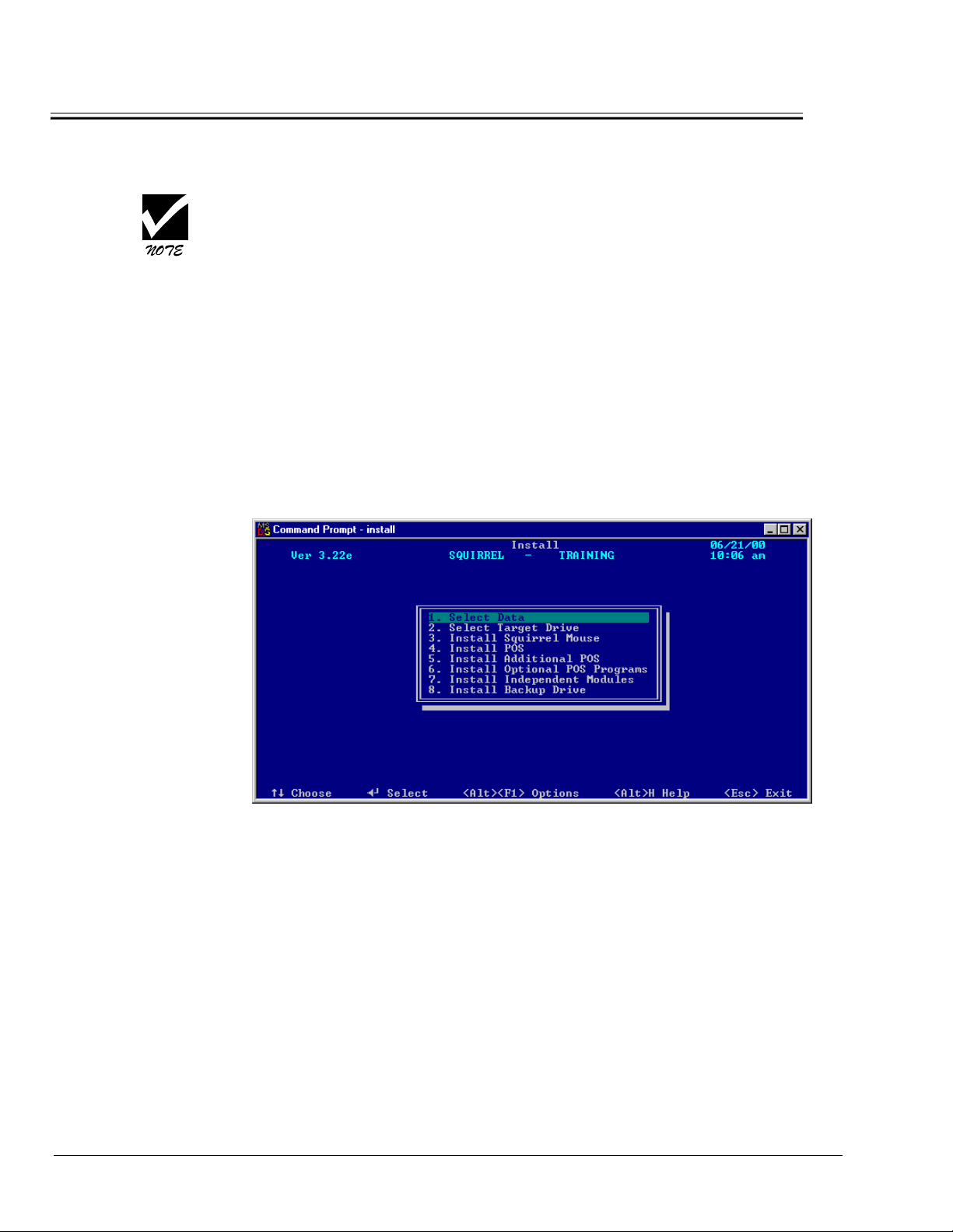
The Install Main Menu screen appears.
3. Select “Install POS “ and hit <Enter>. This will install Squirrel version
3.35b.
4. Once Squirrel is installed, you will be brought back to the main install
menu. If you have Optional Modules (Which will be included on the CD if
you ordered them), select “Install Optional POS Programs” and hit
<Enter>
5. Highlight the module you want install and press <Enter>.
6. Once installed the main menu displays. For each additional optional
module you want installed, you must repeat steps 4 and 5.
6 3/8/01 - Rev 2.0

7. After The Installation is done (Which includes copying in the actual 3.5
files as noted at the top of the previous page), you will need to go into the
“NT_SETUP” folder on the CD Rom and run Setup.exe.
This will then install your icons.
• In previous versions of Squirrel 3.x, you did not need to set up a printer in NT
in order for reports to print. In 3.5 you must have a printer specified as the
default Windows printer in order to print online reports.
• Also see Appendix E: for additional information on modem setup for credit
cards in version 3.5 and 4.01 ( also known as Swtn # 245 )
ROCKETPORT CARD INSTALLATION
Squirrel Version 3.5 is not compatible with octal cards, therefore you must
install the RocketPort card and related drivers. Please remove any existing
octal cards before installing the Rocket Port Card(s)
We are shipping the PCI version of the Rocket Port Card. If you have any
existing ISA Rocket Port Cards, they must be de-configured and removed
from the system before installing the PCI version of the card. Having an ISA
Card installed Before the PCI card could result in the PCI card not being
recognized by the system BIOS. If the ISA Rocket Port Is still required, it can
be installed “After” the PCI card has been installed and configured.
The Rocket Port Card (90-108) is a Multiport Serial card that allows
connection to Host devices such as Credit Card modems, Hotel Interface, and
Host Based Printers.
Please handle the Rocket port card with care, and exercise all anti-static
precautions.
To install the RocketPort card:
Ensure that the PC is powered off.
1.
2. Remove the cover.
3. Ground yourself with an anti-static strip.
4. Select PCI slot and insert card accordingly.
If Installing more than 1 Rocket Port card, please consider the placement of
the cards in the slots. The connector that plugs into the card is fairly large so
having 2 or more Rocket Port cards in adjacent slots side by side may impose
problems when plugging in all the connectors. Please provide adequate
spacing.
5. Ensure that the card is secured to back plate with a screw.
6. Reapply PC cover.
3/8/01 - Rev 2.0 7

SQUIRREL VERSION 3.5 INSTALLATION GUIDE
FOR WINDOWS NT
7. Power on machine and wait for NT to boot up.
Since you will not be “wired” to a physical network, you must have a loopback
adapter installed. This guide also includes information how to set this up
using the MS Loopback adapter and then the RocketPort card.
To install MS Loopback:
1. Point to Start|Programs|Control Panel and select Network.
2. Click YES when asked if you want to install Windows Networking.
3. Select Wired to Network, and click Next.
4. Click on Select from List.
5. Scroll down the list and select the “MS Loopback Adapter” and then click
OK.
6. The MS Loopback Adapter should now be listed and the box next to it
“Checked”. Hit Next.
7. Make sure ONLY the TCP/IP check box is selected, then select Next.
8. Select Next through the next 2 screens.
9. Insert Windows NT disk in CD ROM Drive, and type D:\ (Or the
corresponding drive letter for your CD-Rom drive) in the file location path
window and hit continue.
10. When the MS loopback Adapter Card Setup screen appears, leave the default
setting and select Continue.
11. Click No when asked “if there is a DHCP server on your network.”
12. When the Microsoft TCP/IP Properties window comes up, specify an IP
address for this machine. ( Since this machine is not wired to a network, the IP
address entered doesn’t need to be specific. If you want, put in 192.168.0.1 ).
The Subnet address can be 255.255.255.0 then select OK.
13. When the next window appears ( Bindings), Hit Next. And then Next again to
start the networking service.
14. In the next window you can leave the workgroup as “Workgroup” or change it
to “Squirrel”. Hit Next.
15. Select Finish to complete this part of the setup and the YES to reboot your PC.
After Rebooting and re-logging in, you may get a message saying a service failed
to Start and upon viewing the Event Log it shows 2 Stop Errors noting the
“Server Service” failing to start. This will be corrected after installing Service
Pack 6 once we complete the RocketPort driver setup.
8 3/8/01 - Rev 2.0
To install the RocketPort card driver:
1. c:\Insert The RocketPort Drivers Disk into the A: drive.
2. From the Taskbar, click Start|Programs|Windows NT Explorer.
3. Click on Drive A:\ , click double click on the Executable file ( xxxx.exe ) and
then click unzip into the default assigned directory “ C:\Comtrol “.
4. A message should state that 19 files were unzipped, click OK.
5. Close the Read Me Text window, then close Explorer Window
6. Go to Start|Settings|Control Panel and click on Network.
7. Click the Adapters tab , then click Add.
8. Click Have Disk and point to the C:\comtrol, then click OK.
9. Highlight Comtrol RocketPort/RocketModem, and then click OK.
10. The device wizard invoke and will guide you through the rest of this setup
process.
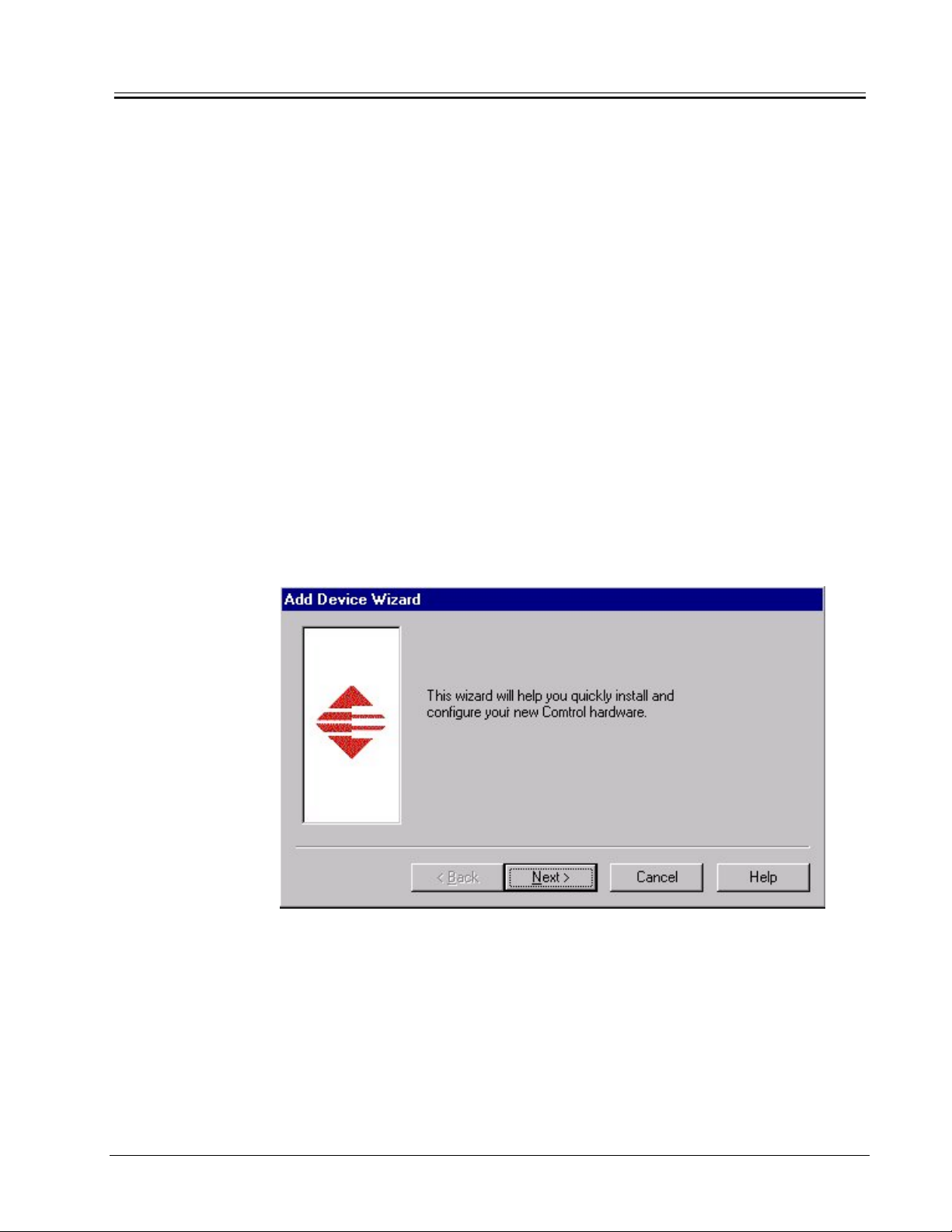
The following screen appears.
1. Click Next.
The following screen appears.
3/8/01 - Rev 2.0 9
SQUIRREL VERSION 3.5 INSTALLATION GUIDE
FOR WINDOWS NT
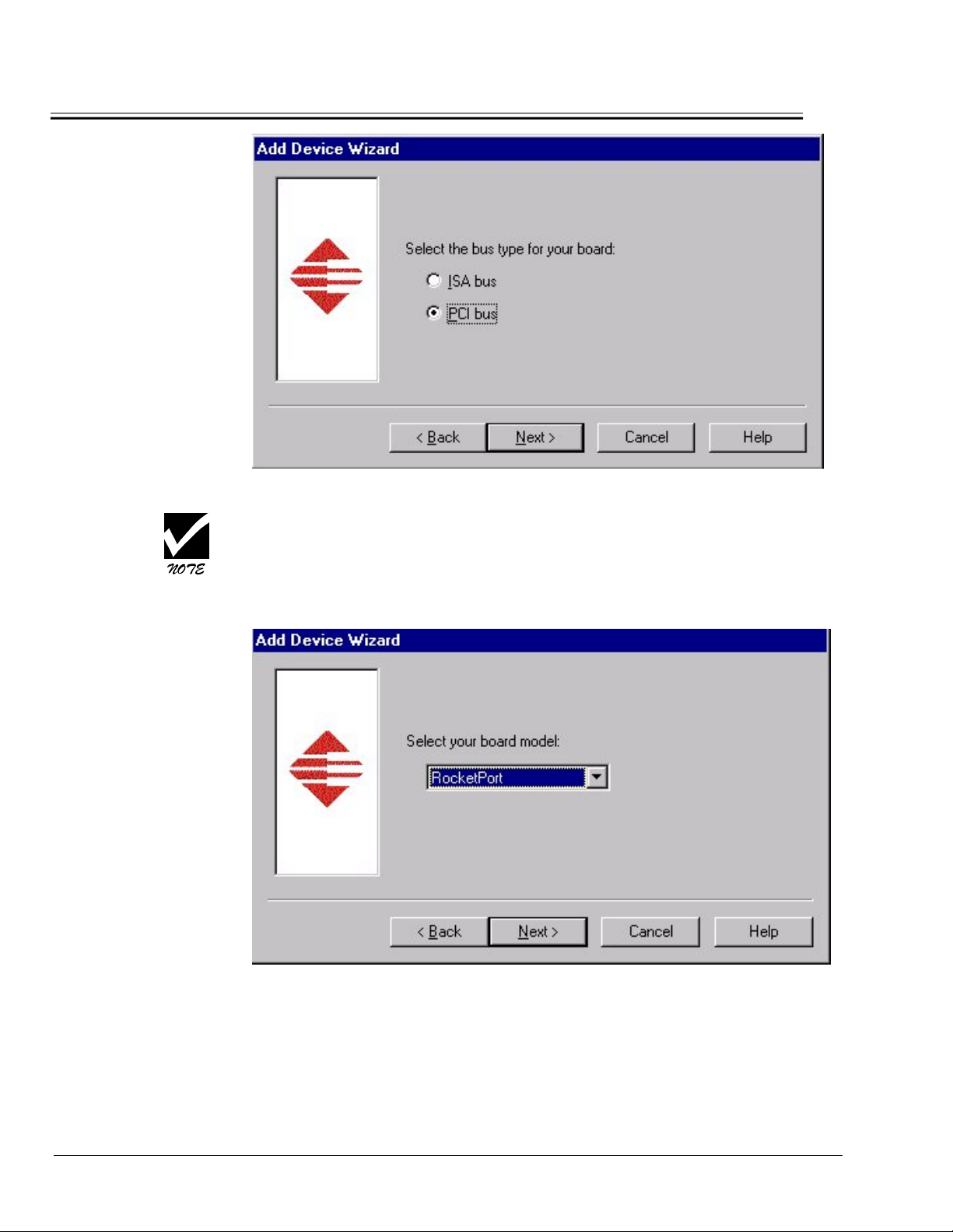
2. Select the Bus type for your board select PCI and click Next.
Please note that on the motherboard (or mainboard) within your PC, the
white slots are PCI and the black slots are ISA.
The following screen appears.
3. Leave Board Model as default and click Next.
The following screen appears.
10 3/8/01 - Rev 2.0
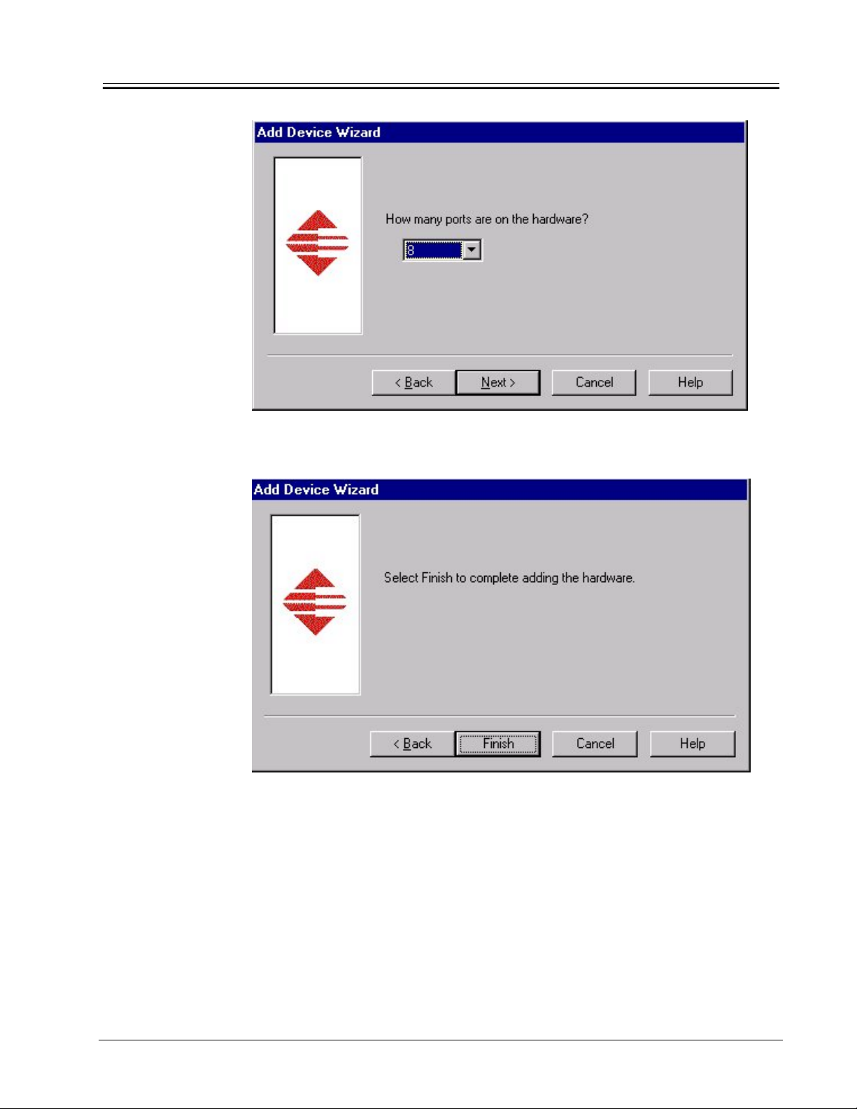
4. Set the Ports to 8 and click Next.
The following screen appears.
5. Click Finish.
3/8/01 - Rev 2.0 11

SQUIRREL VERSION 3.5 INSTALLATION GUIDE
FOR WINDOWS NT
The following screen appears.
Com 7
6. Leave the default Name (Rocket #1). Select COM 7 as your starting
comport, and click OK.
The following is an example of a Com 7 default:
Com 1 = Hotel Interface
Com 2 = Credit Card Interface
Com 3 = PC Anywhere Support/Credit Card Posting
Com 7 = Terminals
A site may only require three Comports, if for example, they are not running a
hotel interface.
The following screen displays.
12 3/8/01 - Rev 2.0

7. Click on the Options Tab.
The following screen appears.
3/8/01 - Rev 2.0 13

SQUIRREL VERSION 3.5 INSTALLATION GUIDE
FOR WINDOWS NT
8. Change the Scan Rate to 1 then click OK.
9. When the message Save Configuration Changes displays. Click Yes.
10. Close the RocketPort setup window, remove any disks from Drive A: and
Restart your PC as indicated.
ADDING ADDITIONAL ROCKETPORT CARDS
To insert additional RocketPort cards:
1. Ensure that the PC is powered off.
2. Remove the cover.
3. Ground yourself with an anti-static strip.
4. Select PCI slot and insert card accordingly.
5. Ensure that the card is secured to back plate with a screw.
6. Reapply PC cover.
14 3/8/01 - Rev 2.0

To configure additional RocketPort cards:
1. Go to Start|Programs|Comtrol RocketPort RocketModem|RocketPort
Setup.
2. Click Add.
The following screen appears.
3. Click Next.
The following screen appears.
4. Click Next.
The following screen appears.
3/8/01 - Rev 2.0 15

SQUIRREL VERSION 3.5 INSTALLATION GUIDE
FOR WINDOWS NT
5. Click Next.
The following screen appears.
6. Click Next.
The following screen appears.
16 3/8/01 - Rev 2.0

7. Click Finish.
The following screen appears.
COM 15
8. Click OK.
The following screen appears.
3/8/01 - Rev 2.0 17

SQUIRREL VERSION 3.5 INSTALLATION GUIDE
FOR WINDOWS NT
9. Click on the Options Tab.
The following screen appears.
18 3/8/01 - Rev 2.0

10. Change the Scan Rate to 1 then click OK.
11. When the message Save Configuration Changes displays. Click Yes.
12. Restart your PC as indicated.
UPGRADING SERVICE PACKS
Service Pack Upgrade
1. Insert Service Pack 6 disk in the CD ROM Drive.
2. Install Wizard guides you through. Click Next when prompted.
3. Click OK to complete the Upgrade.
CONFIGURING STARTING COMPORTS IN SQUIRREL
In order for the RocketPort card(s) to function with Squirrel you must specify
the starting comport in Squirrel Dealer Configuration.
3/8/01 - Rev 2.0 19

SQUIRREL VERSION 3.5 INSTALLATION GUIDE
FOR WINDOWS NT
1. Open a DOS Command Prompt window.
2. Go to the Squirrel\Data\Tomorrow directory and type Dealer then press
<Enter>.
3. Press <Enter> three additional times.
The following screen appears.
7
4. Press <Enter> until the cursor is beside First Com Port to Use and Type 7
and thin hit <Enter>.
5. Press <Esc> to exit.
6. The Squirrel\Data\Tomorrow prompt displays.
7. Type Nuts and press <Enter>.
8. To save the dealer settings you must go in to System Configuration and
escape out.
20 3/8/01 - Rev 2.0

APPENDIX A: SQUiRREL v3.5 UPGRADE System Installation
B
HOST CONVERTER PANEL v1.3a
Connects To Host
PC’s Rocket
Port Card
95-102
DE9 / M
Cabling for
Generic Multiport Serial Card
(90-108)
Pinned Adapters
95-103
Standard SQUiRREL
PN: SQ-7035
RJ12 Cables.
SQUIRREL
RJ12 JACK
INTERFACE
3/7
2/6
1/5
0/4
Converter Modules
Label the handle of each
3
7
2
6
1
5
0
4
A
converter module
according to the device
type and ID number.
PORT 0
PORT 1
PORT 2
PORT 3
C
P1
B
T = TRM
P = PRN
Device
Number
1
PORT 4
PORT 5
PORT 6
PORT 7
0
To PC
USB Port
USB/Host Power
PN: 95-105
Belden & CAT 5 Cables
Label each cable according to the device
type and ID number.
WIRE
COLOR
1
WHITE/GREEN
2
GREEN
3
SHIELD
4
WHITE/ORANGE
5
ORANGE GREEN
CAT 5
BELDEN
COLOR
BLACK
RED
WHITE
RS422
SIGNAL
Rx+
Rx-
Tx+
Tx-
RS232
SIGNAL
Tx
Rx
SHIELDSHIELDSHIELD
GND
Cable Sockets
Record the device type and ID number
5 4 3 2 1
T
1
T = TRM P = PRN
Device Number
1
2
3
3/8/01 - Rev 2.0 21
4
5
6
7

SQUIRREL VERSION 3.5 INSTALLATION GUIDE
r
FOR WINDOWS NT
Power Host Cable from PC USB port. ( Part # 95-105 )
The Converter Panel Ver.1.3a will have the Host Power (+5Vdc/0.5A) via a special cable
from PC USB port (7 feet long). Please note this cable does not come color coded as displayed
below. The connections are polarized which makes it possible to plug the cable in only one
way. When plugging into a mounted converter panel, the red/hot pin will be on the left.
USB/CONN 2 Pin Female
+5VH
GH
7 feet
Pin1/Red wire Pin 1/Red Wire
Pin4/Black wire P2 /Black wire
4 LEG Cable:
(Part # 95-102 )
The 4 x DE9/M connectors will connect the 4 x DE9/M pinned adapter (95-103). For cable
configuration please see the diagrams and the tables:
78 Pin
Conn.
DD-78 pin male Connector to 4 x DE9/M Connectors (Cable 1 to 4)
Labels:1,2,3 & 4
2 feet
Connector
Red Wire
4 x DE9 male
connecto
22 3/8/01 - Rev 2.0

We consider for each channel (port) the following signals:
Cable 1 (0/4) DE9/M
Cable 2 (1/5) DE9/M
DE9 Description DD-
78M
1 RxD Port 0 55
2 RxD Port 4 28
3 TxD Port 0 30
4 TxD Port 4 40
5 GND 68
6 GND 72
7 CTS Port 0 16
8 CTS Port 4 25
9 N/C N/A
DE9 Description DD-
1 RxD Port 1 17
2 RxD Port 5 08
3 TxD Port 1 50
4 TxD Port 5 02
5 GND 69
6 GND 73
7 CTS Port 1 53
8 CTS Port 5 04
9 N/C N/A
78M
Cable 3 (2/6) DE9/M
DE9 Description DD-
78M
1 RxD Port 2 37
2 RxD Port 6 46
3 TxD Port 2 11
4 TxD Port 6 63
5 GND 70
6 GND 74
7 CTS Port 2 59
8 CTS Port 6 09
9 N/C N/A
Cable 4 (3/7) DE9/M
DE9 Description DD-
1 RxD Port 3 56
2 RxD Port 7 27
3 TxD Port 3 10
4 TxD Port 7 64
5 GND 71
6 GND 75
7 CTS Port 3 57
8 CTS Port 7 45
9 N/C N/A
78M
3/8/01 - Rev 2.0 23

SQUIRREL VERSION 3.5 INSTALLATION GUIDE
FOR WINDOWS NT
PINNED ADAPTER (95-103) : DE9/F to RJ12/F
(4 Leg Cable Adapter)
DE9/F Description
1
2
3 Black
4 Yellow
5 White
6 Green
7
8
9
The Red and Blue wires are not pinned to the DE9/F connector. The users (field termination)
will do this. Each adapter has a label with the following information:
• For WS termination:
Port A: Red (wire) to P1 (pin 1)
Port B: Blue (wire) to P2 (pin2)
• For PRT termination:
Port A: Red (wire) to P7 (pin7)
Port B: Blue (wire) to P8 (pin8)
Special Note:
Under special request we can and will deliver the pinned adapter (95-103) with the wires
Pre-Terminated as follows:
a) 95-103 PP
b) 95-103 TP
channel in printer termination.
c) 95-103 TT (Red dot onto label): both channels are in terminal terminations.
(Blue dot onto label): both channels are in printer terminations.
- Red wire pinned to Pin7(DE9/F) connector
- Blue wire pinned to Pin8(DE9/F) connector
(Yellow dot onto label): first channel is in terminal termination and second
- Red wire pinned to Pin1 (DE9/F) connector
- Blue wire pinned to Pin8 (DE9/F) connector
- Red wire pinned to Pin1 (DE9/F) connector
- Blue wire pinned to Pin2 (DE9/F) connector
Fig. Pinned Adapter(95-103)
24 3/8/01 - Rev 2.0

APPENDIX B: SQUiRREL v3.5 New System Installation
A
C
(
)
HOST CONVERTER PANEL 1.41
Complete Panel: 92-251
Motherboard Only: SQ-6081
INTERFACE TO
Generic Multiport
Serial RJ45
JACKS
Connects To Host
PC’s Rocket
Port Card
95-104
SQUIRREL
LEGACY OCTAL
RJ12 JACK
INTERFACE
GENERIC MULTIPORT
SERIAL RJ45 JACK
INTERFACE
7
6
5
4
3
2
1
3
D
7
2
6
1
B
5
0
4
SQUIRREL
LEGACY OCTAL
C
AB
PORT 0
PORT 1
PORT 2
PORT 3
P1
Converter Modules
Label the handle of each
converter module
according to the device
type and ID number.
PORT 4
PORT 5
PORT 6
PORT 7
0
Device
Number
1
4
T = TRM
P = PRN
1
Generic Multiport Serial Card
Belden & CAT 5 Cables
Label each cable according to the device
type and ID number.
CAT 5
WIRE
COLOR
1
WHITE/GREEN
2
GREEN
3
SHIELD
4
WHITE/ORANGE
5
ORANGE GREEN
Cabling for
(90-108)
BELDEN
COLOR
BLACK
RED
WHITE
RS422
SIGNAL
Rx+
Rx-
Tx+
Tx-
RS232
SIGNAL
Tx
Rx
SHIELD SHIELD SHIELD
GND
GENERIC MULTIPORT
DO NOT CONNECT
54321
T
1
T = TRM P = PRN
Device Number
0
TO ETHERNET
Cable Sockets
Record the device type and ID number
Jumper settings for each port
to indicates whether a Printer
or Workstation is attached.
2
3
USB Host Power
Part # 95-105
3/8/01 - Rev 2.0 25
5
6
7

SQUIRREL VERSION 3.5 INSTALLATION GUIDE
r
FOR WINDOWS NT
Power Host Cable from PC USB port.
The Converter Panel Ver.1.41 will have the Host Power (+5Vdc/0.5A) via a special cable
from PC USB port (7 feet long). Please note this cable does not come color coded as displayed
below. The connections are polarized which makes it possible to plug the cable in only one
way. When plugging into a mounted converter panel, the red/hot pin will be on the left.
USB/CONN 2 Pin Female
+5VH
GH
7 feet
Pin1/Red wire Pin 1/Red Wire
Pin4/Black wire P2 /Black wire
( Part # 95-105 )
8 LEG Cable:
( Part # 95-104 )
The 8 x RJ45 connectors will connect the 8 x RJ45 receptacles (Port 0 to Port 7) on
Converter Panel Ver1.4. Below, for cable configuration please see the diagrams and the
tables:
78 Pin
Conn.
10 feet
DD-78 pin male Connector to 8 x RJ45 Connectors (Cable 0 to 7)
Labels :0,1,2,3,4,5,6,7,
Connector
Red Wire
Pin 1
8 x RJ 45 male
connecto
26 3/8/01 - Rev 2.0

We consider for each channel (port) the following signals:
Cable 0 (RJ45)(Lable “0”)
Cable 1 (RJ45)(Label “1”)
RJ45M Description DD-
78M
1 RTS Port 0 51
2 DTR Port 0 49
3 GND 68
4 TxD Port 0 30
5 RxD Port 0 55
6 DCD Port 0 35
7 DSR Port 0 54
8 CTS Port 0 16
RJ45M Description DD-
1 RTS Port 1 31
2 DTR Port 1 32
3 GND 69
4 TxD Port 1 50
5 RxD Port 1 17
6 DCD Port 1 33
7
8 CTS Port 1 53
DSR Port 1
78M
34
Cable 2 (RJ45) (Label “2”)
RJ45M Description DD-
1 RTS Port 2 12
2 DTR Port 2 13
3 GND 70
4 TxD Port 2 11
5 RxD Port 2 37
6 DCD Port 2 39
7 DSR Port 2 58
8 CTS Port 2 59
78M
Cable 3 (RJ45)(Label”3”)
RJ45M Description DD-
1 RTS Port 3 14
2 DTR Port 3 52
3 GND 71
4 TxD Port 3 10
5 RxD Port 3 56
6 DCD Port 3 18
7 DSR Port 3 38
8 CTS Port 3 57
78M
3/8/01 - Rev 2.0 27

SQUIRREL VERSION 3.5 INSTALLATION GUIDE
FOR WINDOWS NT
Cable 4 (RJ45)(Label”4)
RJ45M Description DD-
1 RTS Port 4 21
2 DTR Port 4 22
3 GND 72
4 TxD Port 4 40
5 RxD Port 4 28
6 DCD Port 4 43
7 DSR Port 4 5
8 CTS Port 4 25
Cable 6 (RJ45)(Label”6”)
RJ45M Description DD-
1 RTS Port 6 62
2 DTR Port 6 61
3 GND 74
4 TxD Port 6 63
5 RxD Port 6 46
6 DCD Port 6 48
7 DSR Port 6 29
8 CTS Port 6 9
78M
78M
Cable 5 (RJ45)(Label “5”)
RJ45M Description DD-
78M
1 RTS Port 5 41
2 DTR Port 5 3
3 GND 73
4 TxD Port 5 2
5 RxD Port 5 8
6 DCD Port 5 23
7 DSR Port 5 42
8 CTS Port 5 4
Cable 7 (RJ45)(Label”7)
RJ45M Description DD-
78M
1 RTS Port 7 60
2 DTR Port 7 1
3 GND 75
4 TxD Port 7 64
5 RxD Port 7 27
6 DCD Port 7 6
7 DSR Port 7 26
8 CTS Port 7 45
28 3/8/01 - Rev 2.0

APPENDIX C: Optional Accessories - AVAILABLE SOON
0
1) Octopus Cable Extensions
0
SQ Part #
95-104
8 Leg Octopus Cable
1
6
7
2) 4 Port USB Hub (SQ Part # 90-140)
CAT 5 UTP
Ethernet Cable
SQ-7706
Coupler
0
RJ45-RJ45 Coupler
SQ Part # 95-065
7
Coupler
7
Maximum 25 Feet
Combined Length
Top / Front View
-------------------Back View
3/8/01 - Rev 2.0 29

SQUIRREL VERSION 3.5 INSTALLATION GUIDE
FOR WINDOWS NT
The 4 Port Hub is a Universal Serial Bus (USB) hub, which is a USB cable concentrator and
a bridge between PC USB host controller and USB devices. The USB hub has one
upstream port (root port is not used in the SQUiRREL application) and four downstream
ports ( Ports 1, 2, 3 & 4 ). This hub will be used in self-powered mode to provide the
converter panel (Panel Version 1.4.1) with its host power supply.
System Requirements:
1. The USB Power Supply should be plugged into same power bar as the Host PC.
2. No connection is required between the host PC and the USB hub. The hub is merely
used to supply power for up to 4 converter panels .
Specifications:
Function Description Comments
Upstream port(Root port) 1 Not in use
Downstream port 4 Used to power up to 4 converter
Per-Port Output Voltage (each) DC+5V Power Host Converter Panel
Per-Port Output Current Max.=500mA Provides over-current detection
Power cable length 6 ft.
Dimensions(L x W x H) mm 119x61x23(mm)
LED Red Color Self-powered mode normal for
Weight 100g
Installation:
panels
SQUiRREL use
and protection
Step 1: Insert the plug of DC 6V 2.1A power supply cable into the power jack of the
USB hub.
Step 2: Connect the USB Power Host Cable into downstream port of the USB Hub
(up to 4 ports).
Step 3: Connect the 2 Pin Connector of the Power Host Cable into K21 receptacle
of the Converter Panel.
30 3/8/01 - Rev 2.0

Power Host Cable from PC USB port. ( Part # 95-105 )
The Converter Panel Ver.1.41 will have the Host Power (+5Vdc/0.5A) via a special cable from PC
USB port (7 feet long).
Please note this cable does not come color coded as displayed below.
The connections are polarized which makes it possible to plug the cable in only one way.
When plugging into a mounted converter panel, the red/hot pin will be on the left.
USB/CONN 2 Pin Female
+5VH
GH
Pin1/Red wire Pin 1/Red Wire
Pin4/Black wire P2 /Black wire
7 feet
Connector
3) Rocket Port Expansion Cards
Rocket Port PCI 4 Port Card ( SQ Part # 90-104 )
Rocket Port PCI 16 Port Card ( SQ Part # 90-116 )
With 16 Port Wiring Hub. ( SQ Part # 90-117 )
3/8/01 - Rev 2.0 31

SQUIRREL VERSION 3.5 INSTALLATION GUIDE
FOR WINDOWS NT
Pin Configuration for Rocketport Hub and Standard RJ 45 Cable Receptacles.
Pin
RS-232
Signals
Rocketport Hub
Output RJ-45 Pins
4J/RJ45
1 RTS Pin 1 = RTS
2 DTR Pin 2 = DTR
3 GND Pin 3 = GND
4 TxD Pin 4 = TxD
5 RxD Pin 5 = RxD
6 DCD Pin 6 = DCD
7 DSR Pin 7 = DSR
8 CTS
Pin 8 = CTS
32 3/8/01 - Rev 2.0

4) Rocket Port Adapters
A) Rocket Port Modem Adapter RS-232 serial interface
This adapter is required to adapt the RJ45 plug of the Octopus Cable to the DB25/F
connector of a modem.
Squirrel PN = RJ45 – DB25/M Modem Adapter (Part # :95-132)
Standard Interface Modems use DB25/F connectors.
The following table illustrates the RJ45/F – DB25M adapter connection signals:
RJ45/F Wire
Color
N/A - 1 Not used
4 Red 2 TxD
5 Green 3 RxD
1 Blue 4 RTS
8 White 5 CTS
7 Brown 6 DSR
3 Back 7 Signal Ground
6 Yellow 8 DCD
N/A - 9 to 14 Not used
N/A - 15 Not used
N/A - 16 Not used
N/A - 17 Not used
N/A - 18 Not used
N/A - 19 Not used
2 Orange 20 DTR
N/A 21 to 24 Not used
N/A 25 Not used
B) RocketPort Com Port Adapter DE9 RS-232 serial interface ( 95-131 )
This adapter is required to adapt the RJ45 plug of the Octopus Cable into a standard DE9 style
serial port. This could be used to connect a modem cable.
Standard Interface Modem Cable use DE9/F – DE9/M receptacles.
The following table illustrates the RJ45/F – DE9/M adapter connection signals:
DB25/M RS-232-Signal
Pin 1
Back View
Adapter
RJ45 F
Connector
Pin
DB25 M
Connector
Front View
Adapter
3/8/01 - Rev 2.0 33

SQUIRREL VERSION 3.5 INSTALLATION GUIDE
FOR WINDOWS NT
RJ45/F DE9/M RS-232-Signal
1 7 RTS
2 4 DTR
3 5 Signal Ground
4 3 TxD
5 2 RxD
6 1 DCD
7 6 DSR
8 8 CTS
N/A 9 Not used
To build the adapter:
1) Make the connections following the above table
2) Remove both screws.
3) Install the female screw – lock (62-109)
Pin 1
Back View Adapter
RJ45 F Connector
Pin
DE9/ M Connector
Front View
Adapter
34 3/8/01 - Rev 2.0

APPENDIX D: Setting the performance level in 3.5x
( Also Known As Swtn #238 )
When using SQUiRREL ver 3.35 there can be performance issues at POS
when going into back of the house functions. As with other classic programs,
the CPU usage is high when going into SQUiRREL. With 3.35 the CPU usage
is low when using POS, but the back of the house still uses classic and uses
system resources. If the ‘idle sensitivity’ function in the ‘Misc’ tab of the Pif’s
for SQUiRREL is set to ‘high’, then the CPU usage for that module stays at a
low level. This should alleviate any performance issues related to going into
back of house modules.
3/8/01 - Rev 2.0 35

SQUIRREL VERSION 3.5 INSTALLATION GUIDE
FOR WINDOWS NT
APPENDIX E: Modem setup for Credit Cards in Version 3.5 and 4.01
( Also Known As Swtn # 245 )
The use of a Rocketport card and Rocketport software drivers increases the
number of com ports available to Windows NT. Squirrel Version 3.5 and
Version 4.01 use one com port per terminal or requsition printer configured in
the system. Com ports not used by Squirrel terminals or requistion printers
can be set up to support the use of modems – with some limitations.
To illustrate, examine the setup for a hotel with 4 terminals, 3 requisition
printers, a hotel system interface, a credit card authorization modem and a
credit card posting modem. This configuration requires a total of 10 com
ports – 2 built in to the PC plus an 8 port Rocketport card.
The setup would be as follows:
Com1 – Hotel system
Com2 – Posting modem
Com3 – Authorization modem (on the Rocketport Card)
Com4 – Com10 - Squirrel terminals and requisition printers
NOTE: The following recommendations should be followed:
1. Hotel system should always be set to the built in Com1. This will
reduce the number of variables if troubleshooting is required.
2. For Version 3.5, Credit Card Posting must always be set to a built-in
Com port – i.e. Com1 or Com2. Version 3.5 does not support posting
credit cards to any other Com port.
3. Squirrel devices must be set up to use com ports higher than those set
up for modems. That is, in the above scenario, you cannot set the
Squirrel devices from Com3 to Com9 and authorization on Com10.
This is not supported.
(Continued on next page)
Software Configuration:
36 3/8/01 - Rev 2.0

Rocketport card: The Rocketport software must be configured to support a
modem. To do this, install the Rocketport driver starting with Com3 ( Or
Com 7 if Rocketport was installed as described earlier in the manual ). Next,
to enable the modem for a specific com port, highlight the name of the com
port you wish to configure and click on Properties:
(Continued on next page)
3/8/01 - Rev 2.0 37

SQUIRREL VERSION 3.5 INSTALLATION GUIDE
FOR WINDOWS NT
The following screen appears. Check the box “Emulate modem hardware
RING signal” and click OK to exit.
Click OK again then choose Yes to save the configuration. You will need to
reboot the PC before these changes take effect.
Hardware Requirements:
The following hardware is necessary for the Rocketport to support modems:
1. Host Convertor Panel – Motherboard SQ-6081 which supports RJ45
interface.
2. Cable for Multiport Serial Card – Part 95-104 – connects multiport
serial card to eight RJ45 jacks.
3. Rocket Port Modem Adapter RS-232 serial interface – Part 95-132
which connects RJ45 jack to modem adapter.
38 3/8/01 - Rev 2.0
 Loading...