

Page 1

FLEX
Development kit
because you want to know
User Manual
Page 2

because you want to knowwww.squarell.com
Version Description Date
120313 Initial creation 13- 0 3 -2012
120727 Minor changes 27- 07-2012
120803 Minor changes 03- 0 8 -2012
140 624 Squarell Support Portal added to chapter 9 24 - 06-2014
14 0 811 Fully improved version 11- 0 8 -2 01 4
14 0 911 New design and improved content 11-09-2014
Copyright © 2015 Squarell bv, the Netherlands
Under international copyright laws, neither the documentation nor the software may be copied, photocopied, reproduced, translated or reduced to
any electronic medium or machine-readable from , in whole or in part, without the prior written permission of Squarell bv, the Netherlands, except in
the manner described in the soft ware agreement. iConfigure is a trademark of Squarell bv in the Netherlands.
Microsoft, MS-DOS, Windows, Windows NT, Windows 95, Windows 98, Windows ME, Windows 2000, SQL Server, FoxPro, Excel, Access and
MS Query are trademarks of Microsoft Corporation.
Although care has been taken in preparing the information contained in this document, Squarell bv does not and cannot guarantee the accuracy
thereof. Anyone using the information does so at their own risk and shall be deemed to indemnify Squarell bv from any and all injury or damage
arising from such use.
All rights reserved by Squarell bv.
Page 3

1.
2.
3.
4.
5.
6.
7.
8.
9.
10.
Introduction ...................................................................................................... 3
1.1 About the FLEX Development Kit ................................................................................................ 3
1.2 Kit Contents ............................................................................................................................. 4
CANbus basics ..................................................................................................5
Making an on desk simulation.......................................................................8
3.1 Preparation.............................................................................................................................. 8
3.2 Hardware setup ....................................................................................................................... 8
3.3 Start the second FLEX “2” as interface to the telematics unit / PC ................................................. 9
3.4 Monitor the RS232 output of the Flex with iCheck ......................................................................10
3.5 Monitor the RS232 output of the FLEX with Docklight ..................................................................12
Make scan file from vehicle CANbus or test device .................................15
4.1 Hardware setup ...................................................................................................................... 15
4.2 In vehicle setup with wired connection ......................................................................................15
4.3 Record a CANbus scan with iUpload .......................................................................................16
J1708 signals ................................................................................................... 18
5.1 Hardware setup wired .............................................................................................................18
5.2 Read data from J1708 bus .......................................................................................................18
5.3 Hardware setup DatacliQ ........................................................................................................19
K-Line signals wired ......................................................................................20
6.1 Hardware setup ..................................................................................................................... 20
What to do next? ............................................................................................ 21
CANbus Termination .....................................................................................22
Abbreviations and Terminology ..................................................................23
Technical Support ..........................................................................................24
because you want to knowwww.squarell.com
Content
Appendix ...............................................................................................................25
Page 4

1. Introduction
Thank you for purchasing the FLEX Development Kit.
We are confident that the FLEX development kit provides the means to create powerful vehicle data solutions
based on CANbus, J1708 and K-line.
1.1 About the FLEX Development Kit
The FLEX Development Kit is a total solution to start using FLEX in trucks, vans and cars equipped with a CANbus.
With this kit you are able to:
• Make an on desk simulation for a driving truck
• Make CANbus scans from vehicles
• Replay CANbus scans in your on desk simulation
• Load new software into the Squarell FLEX device
• Install the FLEX in a truck connected to your telematics solution
This manual describes how to:
• Set up a working environment with software and hardware
• Learn how to do the basic tasks like monitoring and simulation of the vehicle data network
If you have any questions or need additional information, please do not hesitate to contact us
via our support portal or via your account manager.
After using this kit set up, both Flex devices can be reused in any supported vehicle.
because you want to knowwww.squarell.com
3
Page 5
1.2 Kit Contents
because you want to knowwww.squarell.com
Quantity Product Product Name
2 FLEX12 FLEX device
1 x FLEX loaded with SQU-FLX12-TDK.DCF
1 x FLEX loaded with SQU-8000-TRKS-000000.DCF
1 8510-28 0 J1708 DatacliQ cable
1 USB to RS232 USB cable with a RS232 connector
1 Combined cable Consists of 8612-U1, 8612-CQ and Power supply
2 CANcliQ cover
1 DatacliQ cover
Software
iUpload Downloadable from support.squarell.com
iCheck Downloadable from support.squarell.com
Docklight (evaluation version) Downloadable from support.squarell.com
Expertview www.expertview.live.com
Other downloads
FLEX user manual Downloadable from support.squarell.com
iCheck user manual Downloadable from support.squarell.com
iUpload user manual Downloadable from support.squarell.com
Squarell RS232 protocol Downloadable from support.squarell.com
4
Page 6
because you want to knowwww.squarell.com
5
2. CANbus basics
In the next chapters we discuss how to:
• Create a desk simulation of a vehicle
• Create a desk simulation for vehicle data reading
• Understand the RS232 output
• Check the output via iCheck tool
• Understand the CAN output check the output via iUpload tool
Please read the following instruction guidelines before starting the installation procedure:
CANbus
CANbus is a data network for the vehicle.
It reads technical data like:
Engine speed, fuel consumption, Torque, pedal position, PTO, Retarder, ABS, Cruise, Temperature.
All the Euro3-4-5-6 truck models have CANbus.
[and other vehicles, vans, cars, machines, trains, ships, airplanes]
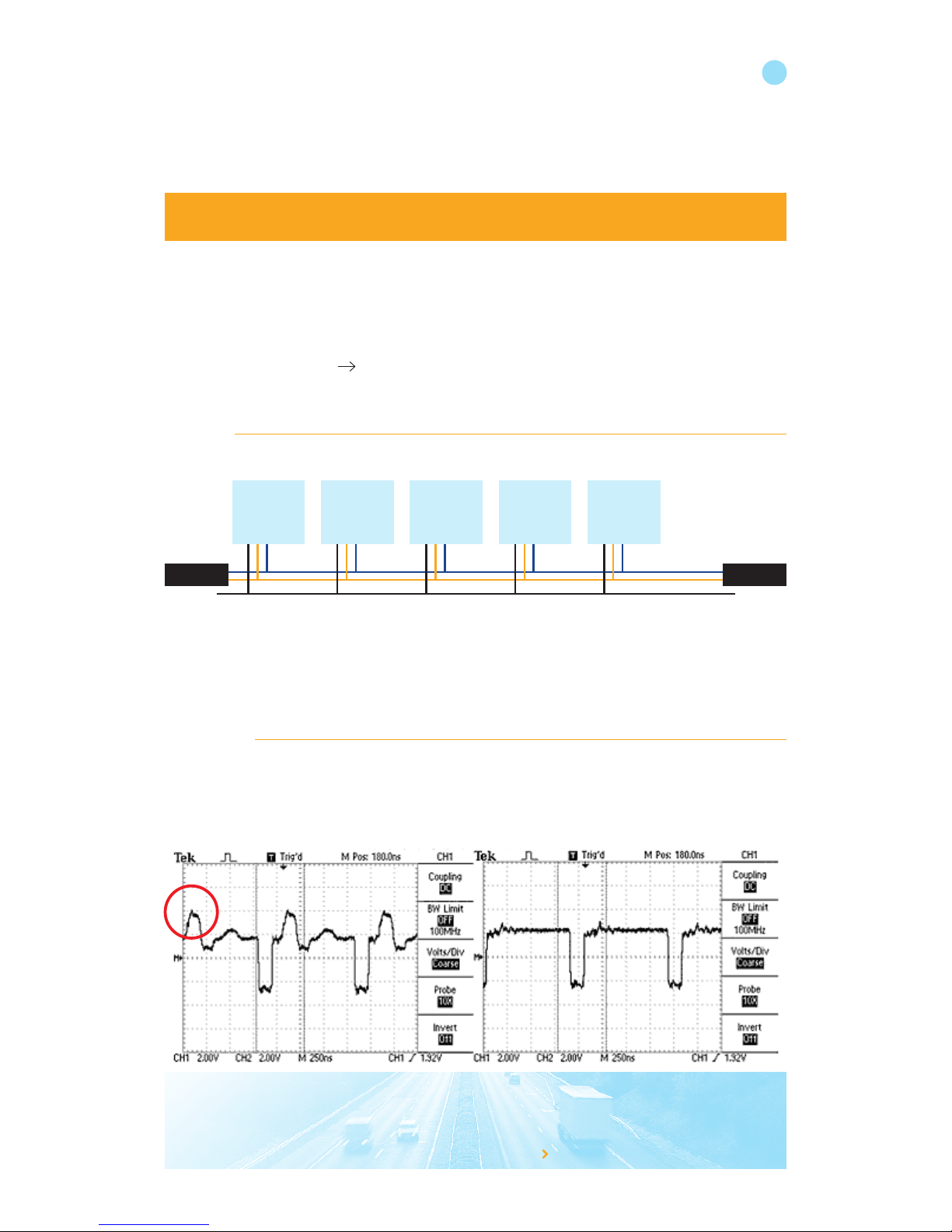
Termination
Termination resistance avoids reflections of the CANbus signal. A proper CANbus needs to have a 120 termination on
both ends of the CANbus. Missing a terminator or a terminator in the wrong place can cause errors on the CANbus.
Without termination With termination
(in red circle effect of missing terminator)
CANbus
Electronic
diesel
controler
Ground
ABS/EBS
brake
systems
Automatic
gearshift
Retarder PTO
Terminator
120 Ohm
Terminator
120 Ohm
Page 7
Firmware
The FLEX firmware handles the communication between the hardware and the software (DCF) loaded in the device.
Squarell recommends to always use the latest firmware version (announced on support.squarell.com) to benefit from the
latest developments and bug fixes. A new firmware version can be loaded using Squarell iUpload. A new device is
always loaded with the latest firmware version available.
DCF
DCF is a Device Configuration File (software). It programs the device how to handle the incoming and outgoing data.
The two software files (DCFs), pre loaded on the TDK devices, are used for the following purposes:
TRUCK SIMULATION DCF (SQU-FLX12-TDK.DCF, loaded on device number 1)
This DCF sends random data over the J1708, K-line and CANbus1.
With this data, tests can be performed to capture vehicle data, monitor and record FLEX messages.
FLEX DCF for Trucks (SQU-8000-TRKS-000000.DCF, loaded on device number 2)
These DCFs are DCFs with RS232 and CANbus output.
The input is via the CANcliQ or direct hardwire into the vehicle CANbus.
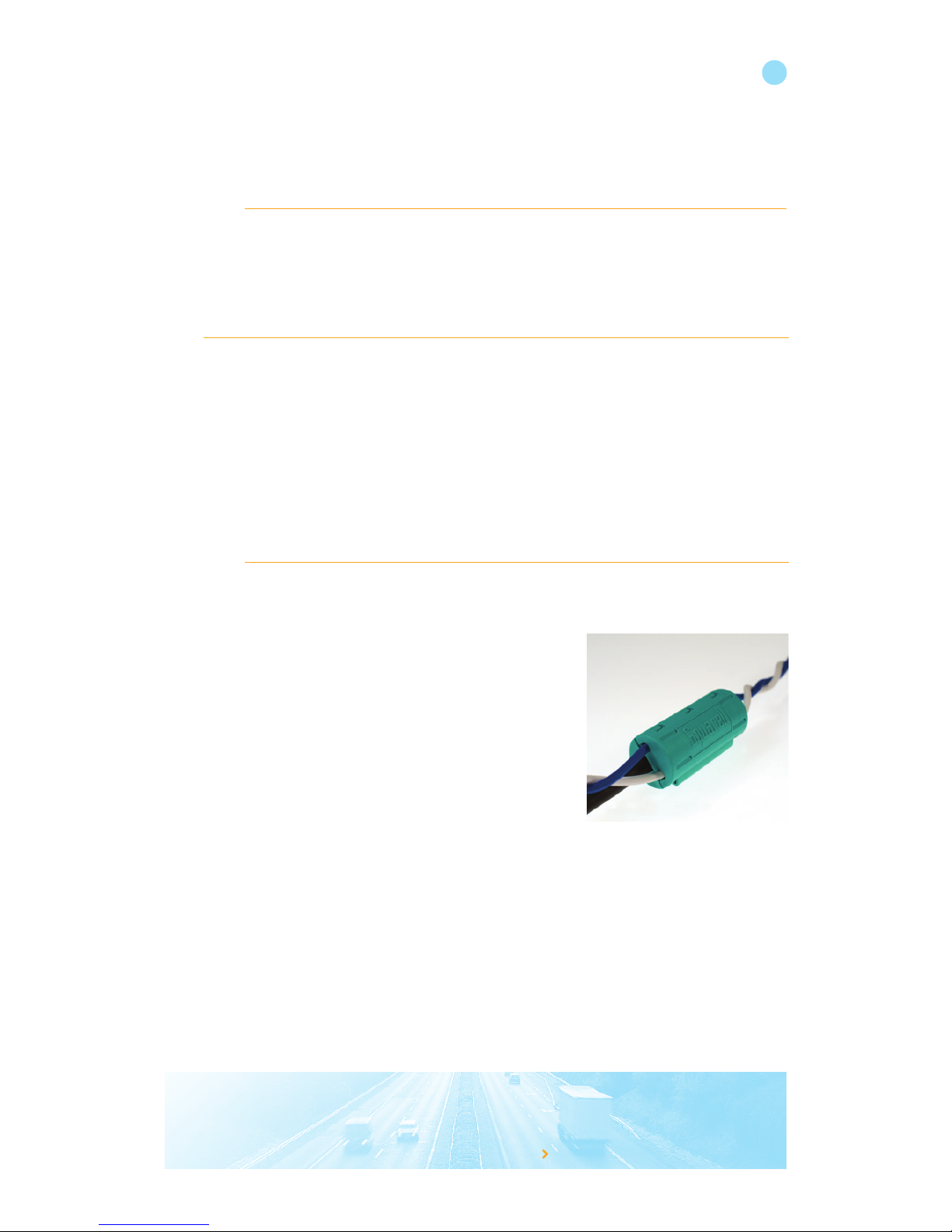
CANcliQ
The Squarell CANcliQ reads vehicle signals without making a wire-to -wire connection. This technology guarantees
that non intrusive signals are sent to the vehicle CANbus. This eliminates liability matters, warranty issues or possible
wrong connections.
Benefits
• No direct CANbus connection
• One cable fits all vehicles
• 100% non intrusive technology
• Safe and reliable reading of CANbus data
• No soldering, wire cutting or crimping
• No physical wire to wire connections
• Isolation of vehicle wires stays intact
• Quick installation
• No warranty and liability issues
The CANcliQ is standard on all our interface modules.
because you want to knowwww.squarell.com
6
Page 8
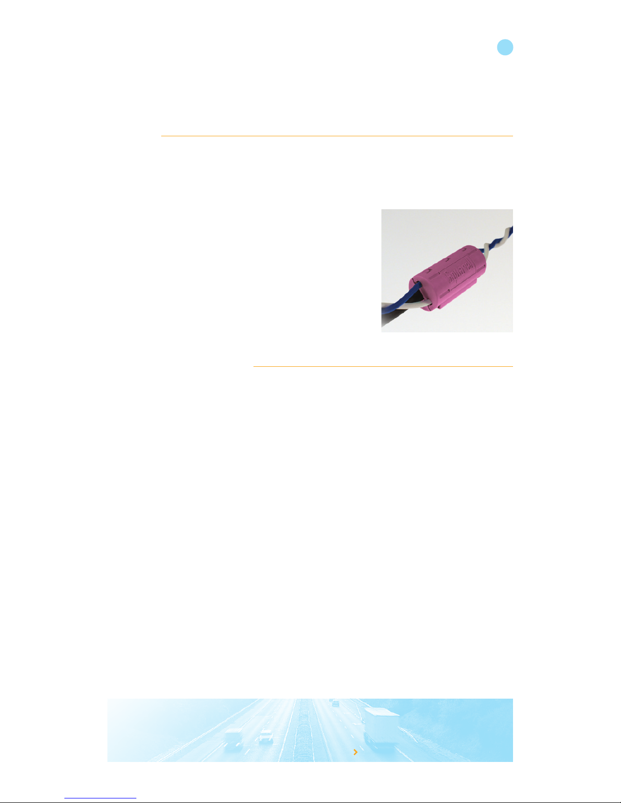
DATAcliQ
With the DATAcliQ, we can retrieve data from several sources continuing to offer better and more complete vehicle
data solutions. While we ensure that retrieving vehicle data is non intrusive and safe, we offer a more complete and
richer user experience.
At this moment Squarell has DATAcliQ’s available to read CANbus, J1708 or ISO11992.
Output RS232/CAN protocol
All Squarell devices are configured to send output data via RS232 and CAN. The output of every standard Squarell DCF
is conform the respective protocol. The advantage of the RS232 output is that we have set the most important vehicle
parameters in standard data strings. Based on these parameters, you can develop reports for advanced vehicle and
driver behaviour. The integration is easy as many modems or tracking units can transmit the data immediately.
The advantage of the CANbus output is that the device is a real replacement for the vehicle’s FMS interface. The FMS interface is used as a safe connection between the vehicle’s CANbus and a modem or tracking unit. Besides the standard
FMS/CANbus messages, Squarell has added additional parameters that can be used to create advanced reports.
You can identify a Squarell DCF by the “SQU” tag in the first digits of DCF name.
To get familiar with the standard Squarell output we advise you to read the Squarell RS232 protocol description and the
Squarell CANbus protocol description, which can be found in the download section on the Squarell support portal.
because you want to knowwww.squarell.com
7
Page 9
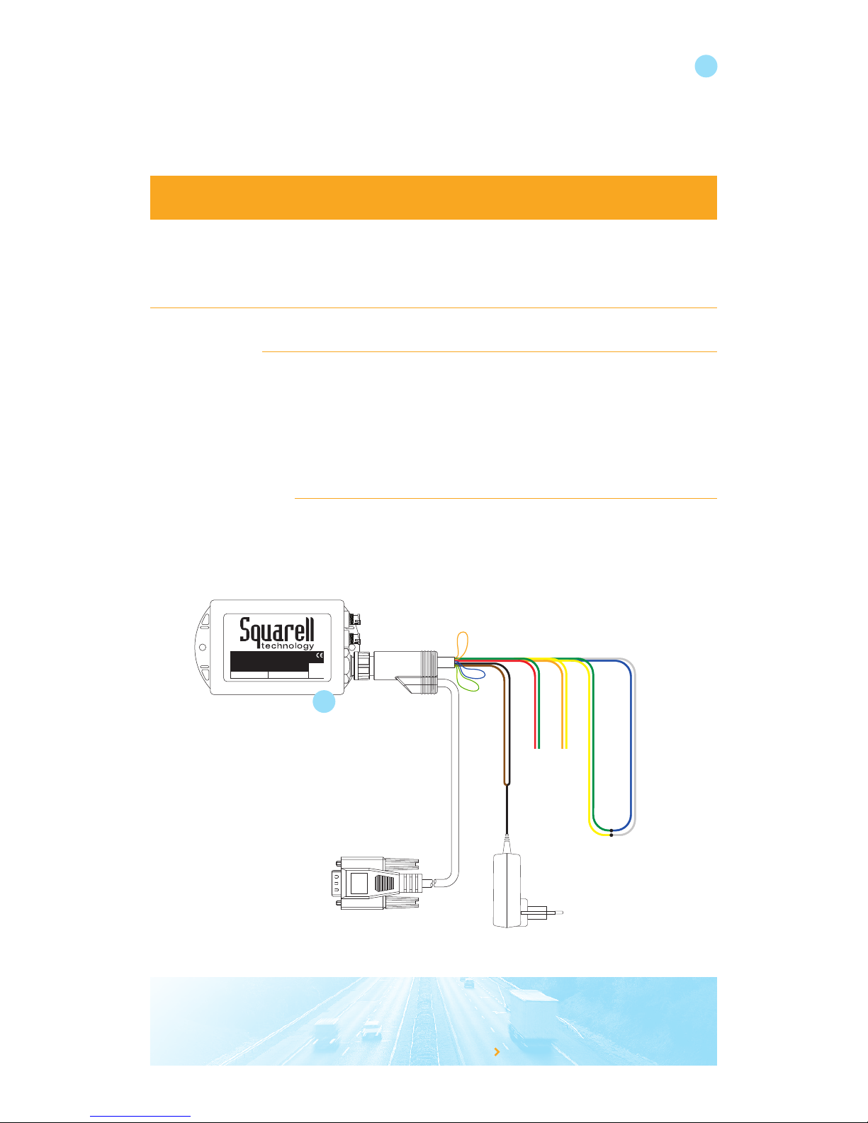
3. Making an on desk simulation
The first step is to have one FLEX unit (marked with number 1 = simulates a truck) act like a vehicle CANbus. From
this simulated vehicle CANbus the other FLEX unit (marked with number 2) reads the CANbus and converts the
data into the Squarell RS323 output data.
3.1 Preparation
• Download and install Docklight*
• Download and install iCheck*
• Download and install iUpload*
• Request an Expertview account (if not already done)
• Remove the end termination from the cables yellow/green & white/blue
* from support.squarell.com
3.2 Hardware setup
The parts that are needed are:
• FLEX “1” device
• cable xxxxx
Make the following setup:
The FLEX device is pre-loaded with the truck simulation software. This software (also known as DCF) simulates a
trip of a truck and can be used for testing.
because you want to knowwww.squarell.com
BU WH
YE GR
FLEX
Multi Source Vehicle Data Interface
S/N: 27197809Type: FLX12
12p SFD ASFD B
Sending Device
Not connected
OG YE
RD GRBN BK
BU
OG
GR/YE
USB
8
1
Page 10
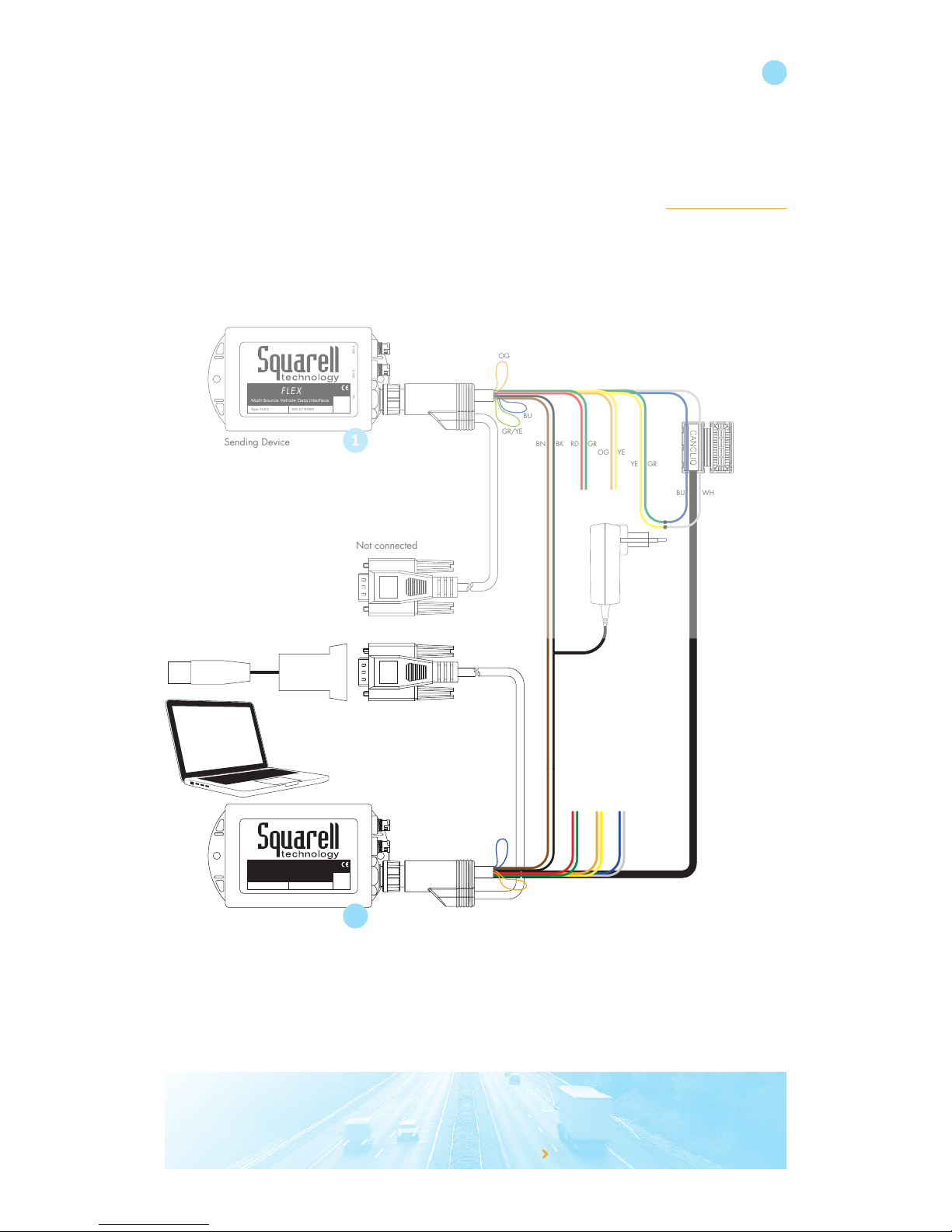
3.3 Start the second FLEX “2” as interface to the telematics unit / PC
• FLEX “2” device
• 8612-CQ 12-Pole Cable with CANcliQ
• 1 PC with serial port or USB port (please make sure correct drivers are installed)
Connect FLEX “2” to the setup as in the picture:
Click the CANcliQ around the Blue/White CANbus of device FLEX 1, it picks up the signal (white is CAN high, blue
is CAN low). As the CANcliQ only closes once, it is recommended to remove the locks and use tie wraps to close the
CANcliQ (later you can replace the modified CANcliQ cover by the spare one provided in the kit).
The Squarell standard trucks DCF is pre-loaded in the FLEX 2 device. This software (also known as DCF) supports trucks
and can be used for testing. The DCF processes, cleanses, filters, calculates and checks the received data and converts
the data to proper output (this can be RS232 and/or CANbus). Both the RS232 output as well as the CANbus output
(blue/white) are activated.
because you want to knowwww.squarell.com
FLEX
Multi Source Vehicle Data Interface
S/N: 27197809Type: FLX12
12p SFD ASFD B
FLEX
Multi Source Vehicle Data Interface
S/N: 27197809Type: FLX12
12p SFD ASFD B
Receive Device
Sending Device
To PC
with RS232 monitor
Not connected
BU
WH
YE GR
OG YE
RD GRBN BK
BN BK
OG YE
BU WH
RD GR
BU
OG
OG
BU
GR/YE
USB
USB
9
1
2
Page 11
because you want to knowwww.squarell.com
10
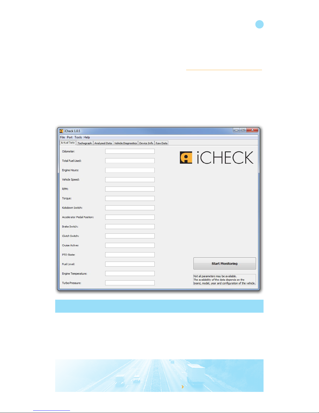
3.4 Monitor the RS232 output of the Flex with iCheck
Squarell has created a tool to easily perform a quick check of the installation. The program “iCheck” can be installed on
a laptop or PC and shows you the RS232 output of the device. When you see the most important parameters coming
through, you are sure that you have installed the Squarell device with the correct CANbus, J1708 and/or K-line (currently
iCheck only works together with Squarell DCF’s with RS232 output).
Download iCheck from the Squarell Support portal.
Run the program after the installation is completed.
Connect the RS232 cable of device 2 (see 3.3) to your PC (or via USB - RS232 to a free USB port).
Make sure the RS232 port is not in use by any other program (like Docklight)
Page 12
because you want to knowwww.squarell.com
11
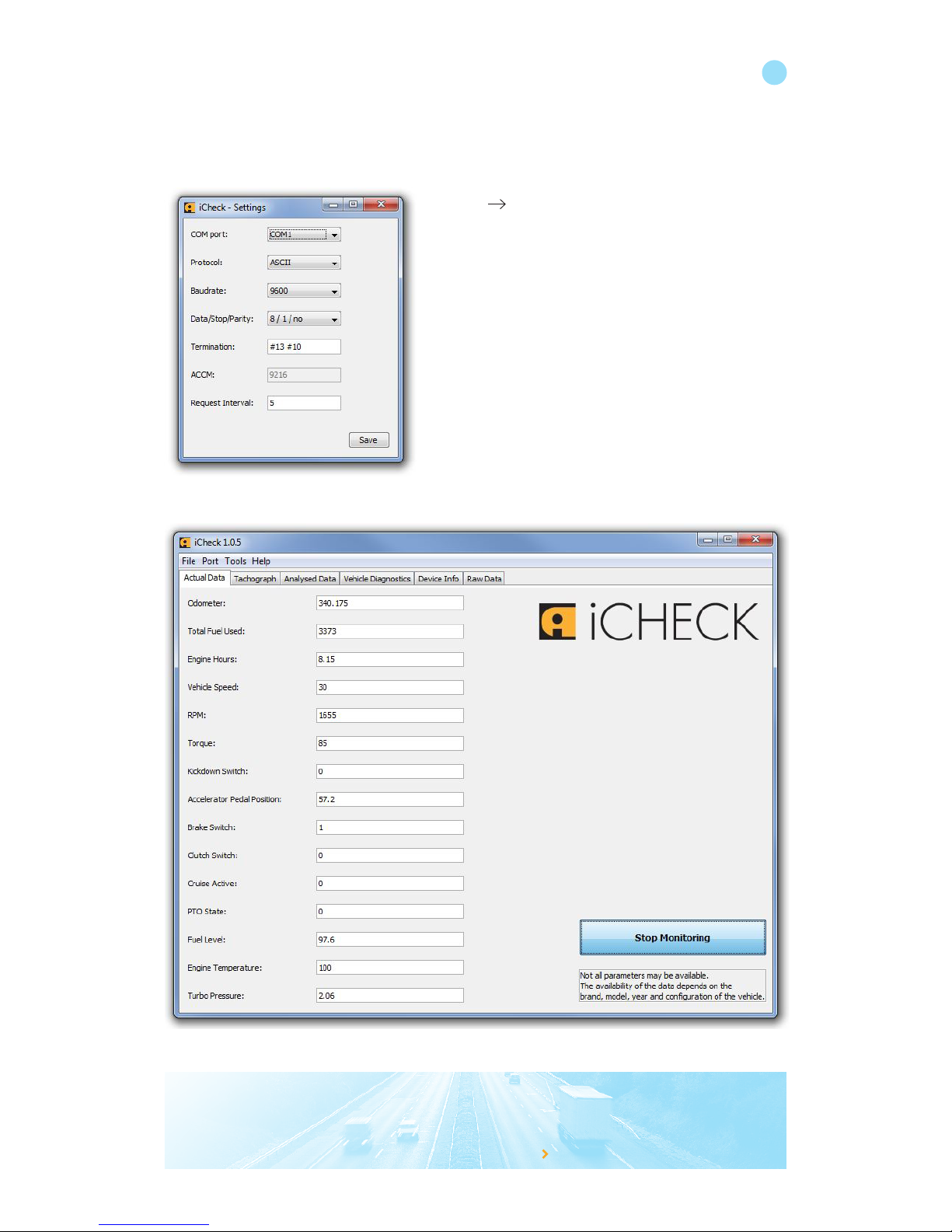
Click on “Start Monitoring”
When the installation is done right, the values for the parameters will appear.
Select Port Settings and select the right COM port.
All other default settings are right for this test.
More information on iCheck can be found in the manual which is downloadable from the Support portal.
Page 13
because you want to knowwww.squarell.com
12
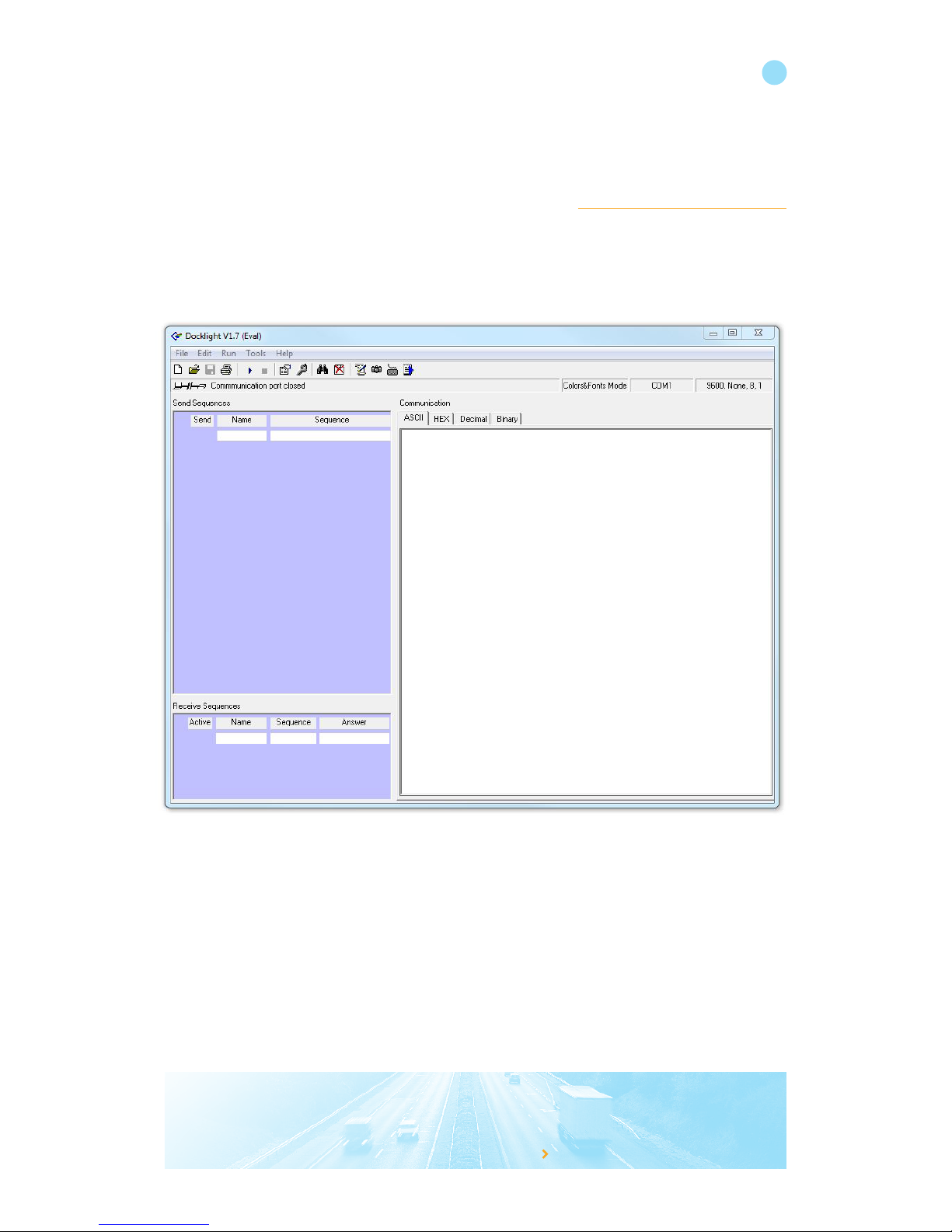
3.5 Monitor the RS232 output of the FLEX with Docklight
Connect the RS232 cable of device 2 (see 3.3) to your PC (or via USB - RS232 to a free USB port).
On the PC start the program “Docklight” (you can download Docklight from support.squarell.com).
Select the appropriate com port for the RS232 cable.
Double click on the COM port to modify the settings.
Select the baud rate 9600, 8 bits, 1 stop bit, No parity.
Page 14
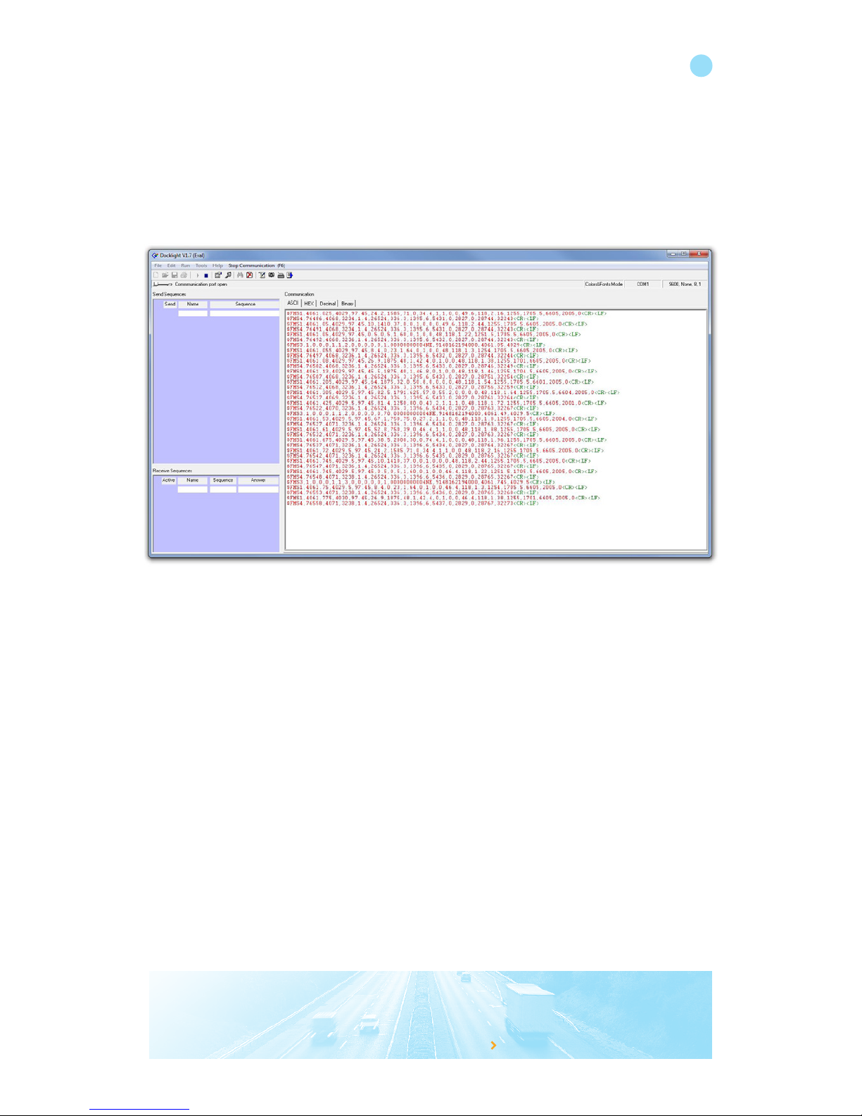
FLEX 1 has preloaded software (DCF) that is simulating a vehicle.
Press the play button.
Docklight is now showing the Data that is processed in FLEX 2 and read from the CANbus with the CANcliQ
$FMS1,4061.025,4029,97.45,24.2,1585,71,0,34.4,1,1,0,0,49.6,118,2.16,1255,1705.5,6605,20 05,0<CR><LF>
The Squarell RS232 protocol Document (downloadable from the support portal) shows you what the data means.
Chapter 3.2 “Detailed description of the $FMS1 message” gives information on the messages.
The following text is copied from the Protocol Document:
“This message is sent every 5 seconds at default. The format of the message is:
$FMS1,<value1>,…,<value20><CR><LF>”
because you want to knowwww.squarell.com
13
Page 15

because you want to knowwww.squarell.com
14
No. Parameter Description Unit Signification
1 Odometer Total vehicle distance km 1/2 0 0
2 Total fuel (*1) Total fuel used (TFU) liter 1/2
3 Engine hours Total engine hours hour 1/2 0
4 Actual speed Actual vehicle speed km/h 1/10
5 Actual engine speed Actual engine speed RPM 1/8
6 Actual engine torque Actual engine torque % 1
7 Kick down switch State of the kick down switch 0= no 1=yes 1
8 Accelerator pedal
position
Position of the accelerator pedal % 4/10
9 Brake switch State of the brake switch 0= no 1=yes 1
10 Clutch switch State of the clutch switch 0 = no 1=yes 1
11 Cruise active State of the cruise control 0= no 1=yes 1
12 PTO active *2 State of the PTO see (*2) 1
13 Fuel level Percentage fuel level % 4/10
14 Engine temperature Coolant temperature of the engine Celsius 1
15 Turbo pressure Turbo pressure of the engine bar 1/50
16 Axle weight 0 Weight of the steering axle of the
vehicle
kg 1/2
17 Axle weight 1 Weight of the first axle of the vehicle kg 1/2
18 Axle weight 2 Weight of the second axle of the
vehicle
kg 1/2
19 Axle weight 3 Weight of the third axle of the vehicle kg 1/2
20 Service distance Distance to drive until next service km 1/10
As you can see from the example Data string:
Parameter 1 is Odometer and has a value of 40 61.0 2 5 km
Parameter 2 is Total Fuel and has a value of 4029 Liter
Parameter 3 is Engine Hours and has a value of 97. 4 5 hours
In this example $FMS4 is also sent every 5 seconds and $FMS3 is sent every 30 seconds.
Page 16
4. Make scan file from vehicle CANbus or test device
With a scan file you can make an extraction of the CANbus data from a vehicle. You can also simulate this on
your desk, using the setup below.
4.1 Hardware setup
The parts that are needed are:
• 1 * FLEX device FLEX12 loaded with a reset dcf (use iUpload to load reset dcf)
• 8612-U1 or 8612-CQ 12-pole cable (both part of the combined cable)
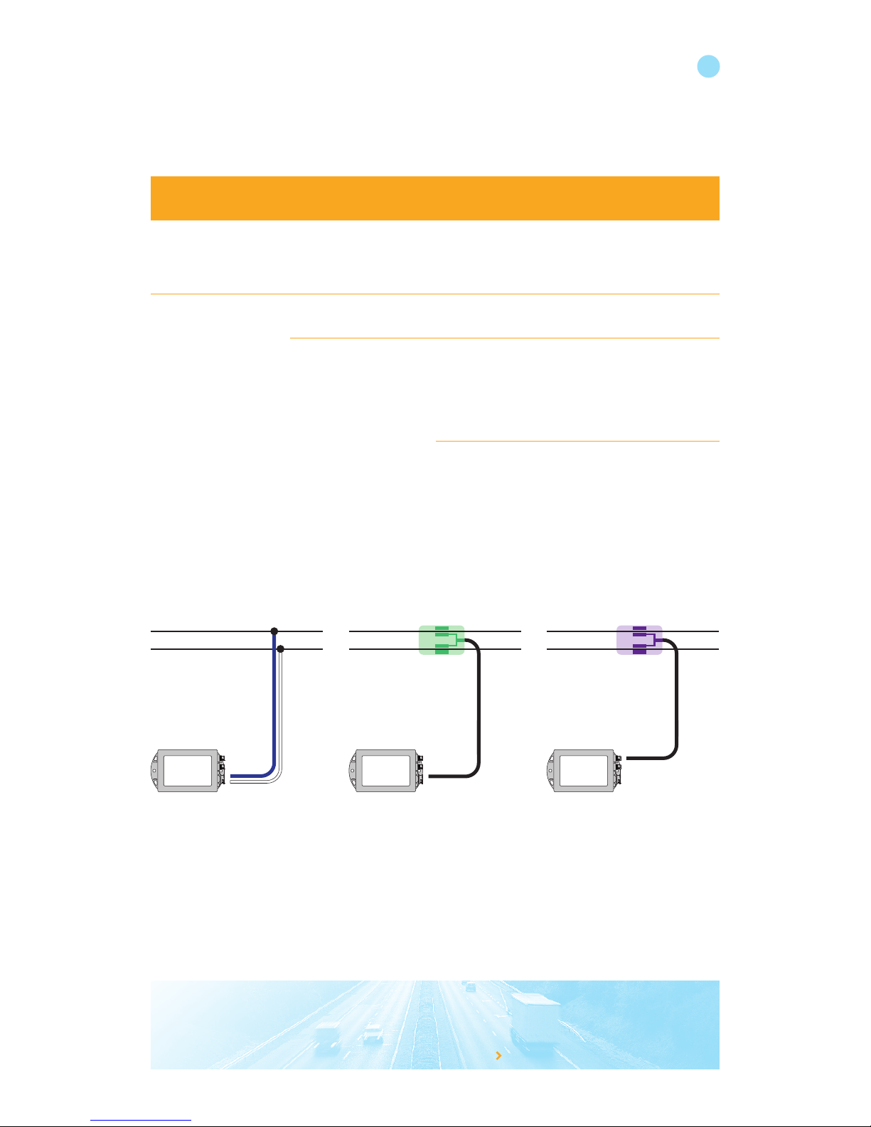
4.2 In vehicle setup with wired connection
In the vehicle make sure the power and ground are well connected.
Find the CANbus wires by using the Squarell installation instructions (all instructions are included in the Squarell
Installer certification training package, these trainings are run every month at squarell). For a installation instruction
you can contact the Squarell support department.
A CANbus scan can be made by using the blue/white wires, a CANcliQ or a DatacliQ for CANbus.
When using the wired connection the FLEX CANbus will be connected to an existing CANbus both Terminators in
the FLEX cable need to be removed. See chapter 8 for more information on CANbus termination.
• Cut the blue loop near the connector
• Cut the terminator at the end of the flying leads
Connect the FLEX device to the PC via the RS232 cable.
because you want to knowwww.squarell.com
15
CANcliQ
Squarell
FLEX
DatacliQ
Squarell
FLEX
DatacliQ
Squarell
FLEX
DatacliQ
Squarell
FLEX
Page 17
4.3 Record a CANbus scan with iUpload
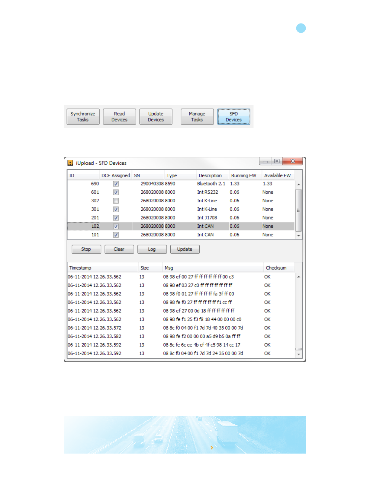
Start iUpload and click on “read devices” to locate the connected FLEX device. Click on the device line to select the
correct device.
because you want to knowwww.squarell.com
16
Monitor and log SFD Device port (CANbus scanning)
By selecting the requested SFD port you can monitor the activity on that port. Click on the correct SFD device and click
on ‘Start’ button. You should now see all incoming data on that port (takes 2-3 seconds).
To make a CANbus scan via a wired connection select ID 101.
To make a CANbus scan via a CANcliQ connection select ID 102.
To make a CANbus scan via a DatacliQ for CANbus select ID 180 (or 181).
Page 18
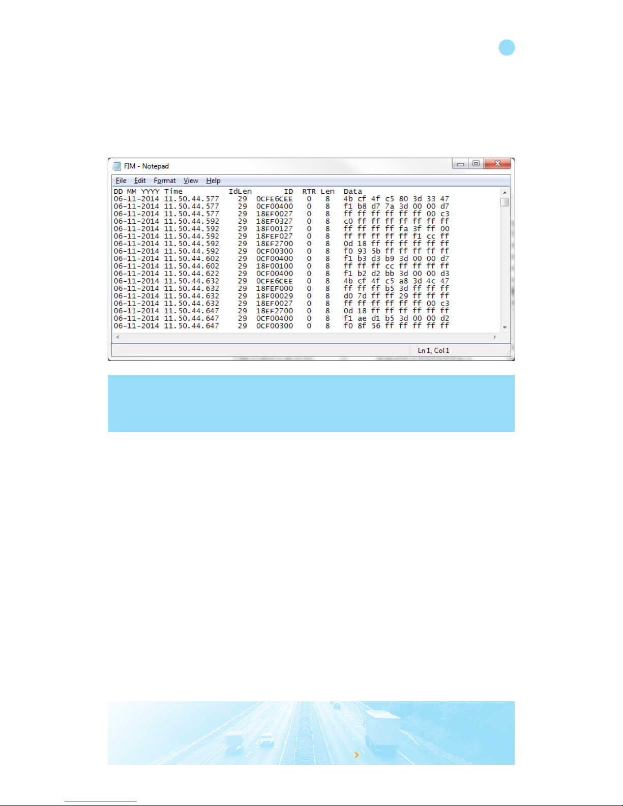
You can save the message log by clicking the ‘Log’ button. The below window appears. This .txt file can be saved to
a location on your PC.
because you want to knowwww.squarell.com
17
Note:
With above monitor option you can make a live vehicle CANbus scan using a wired connection, the CANcliQ
or DataCliq. This CANbus scan can be sent for analysis to the Squarell Technical department. But you can also
monitor incoming messages from the Bluetooth device for example.
Page 19
because you want to knowwww.squarell.com
5. J1708 signals
5.1 Hardware setup wired
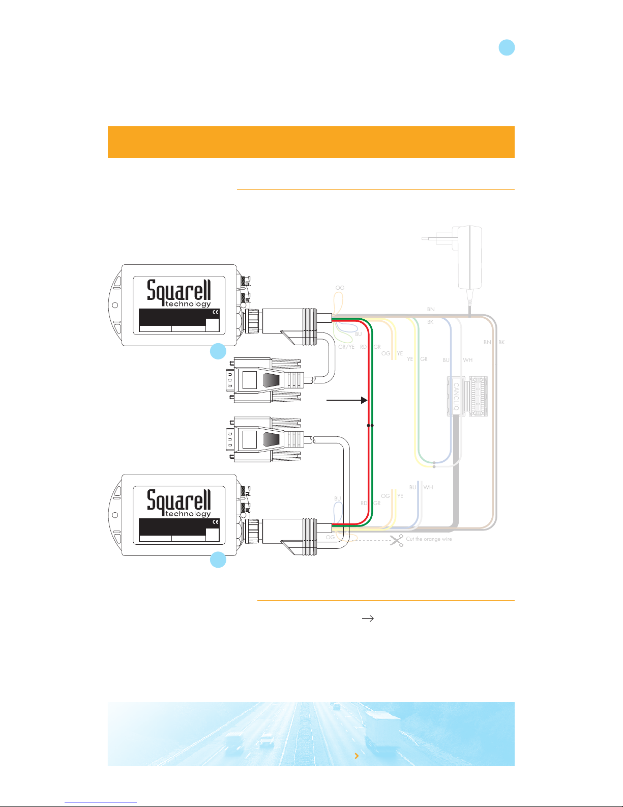
To test multiple signals besides the CANbus this setup should be made. Connect green and red from Flex no. 1 to
green and red of Flex no.2.
18
BU
OG
Cut the orange wire
BU WH
YE GR
OG YE
RD GR
RD GR
OG YE
BU WH
BN BK
BN
BK
BU
OG
GR/YE
FLEX
Multi Source Vehicle Data Interface
S/N: 27197809Type: FLX12
12p SFD ASFD B
FLEX
Multi Source Vehicle Data Interface
S/N: 27197809Type: FLX12
12p SFD ASFD B
Test Device
Truck simulator Device
To PC / Telematics Device
J1708
5.2 Read data from J1708 bus
Open iUpload and start the Function interface Mode (select the device Select SFD Devices
Choose the “internal J1708”channel (ID201) and press start. The J1708 Data as received by FLEX #2 is shown.
After clicking “Stop”, this data can be saved as .txt file by clicking the “Log” button
The same can be done with a DatacliQ for J1708 connected to FLEX#2. And connected to green and red J1708
wires of FLEX #1.
1
2
Page 20
because you want to knowwww.squarell.com
19
5.3 Hardware setup DatacliQ
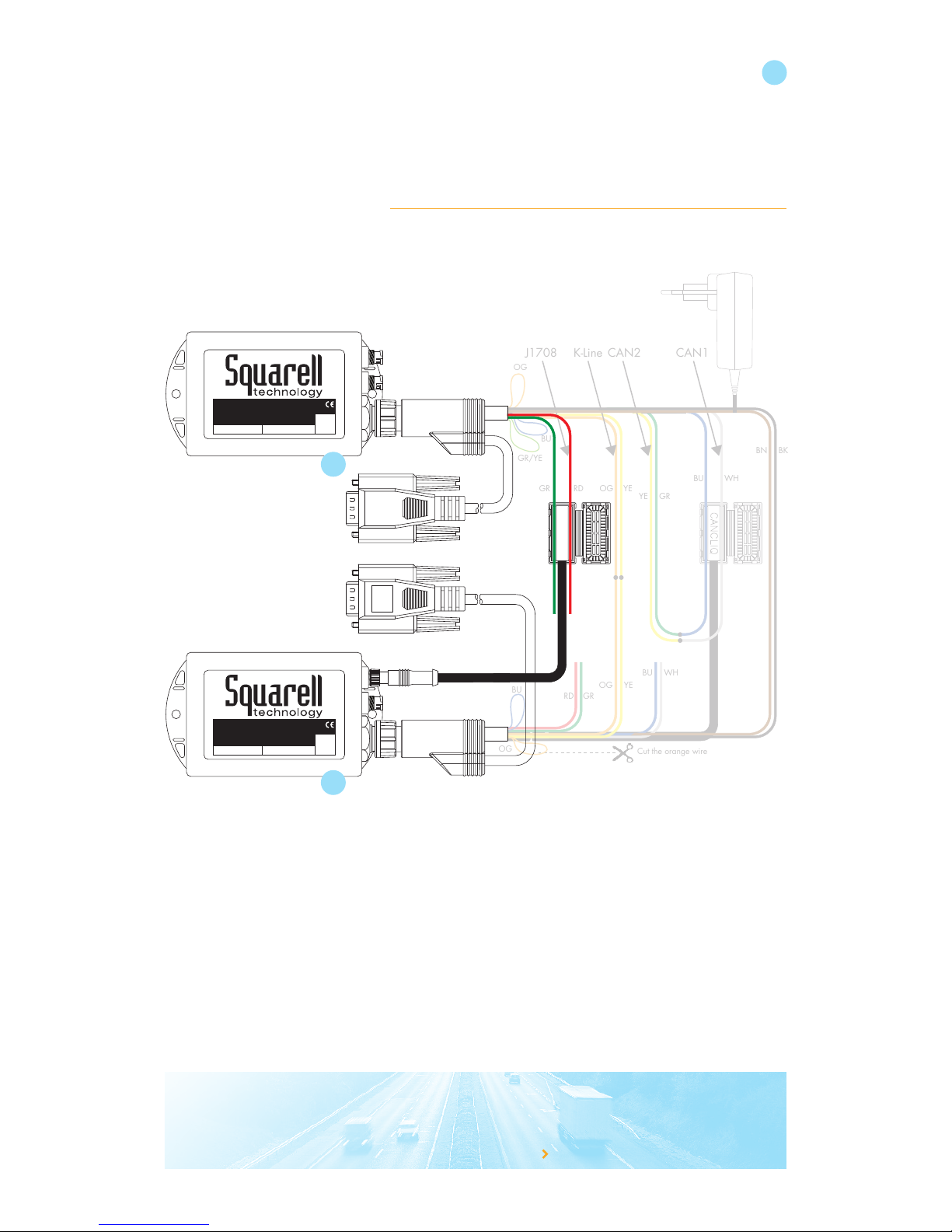
To test multiple signals besides the CANbus this setup should be made
The DatacliQ can be connected to SFD1 or SFD2 port. The FLEX will identify the signal automatically.
Please “read the devices” again to be able to see the new ID.280.
BU
Cut the orange wire
BU WH
YE GR
OG YERDGR
RD GR
OG YE
BU WH
BN BK
BU
OG
GR/YE
J1708 K-Line CAN2 CAN1
OG
FLEX
Multi Source Vehicle Data Interface
S/N: 27197809Type: FLX12
12p SFD ASFD B
FLEX
Multi Source Vehicle Data Interface
S/N: 27197809Type: FLX12
12p SFD ASFD B
Test Device
Truck simulator Device
To PC / Telematics Device
DATACLIQ
280
1
2
Page 21
because you want to knowwww.squarell.com
6. K-Line signals wired
6.1 Hardware setup
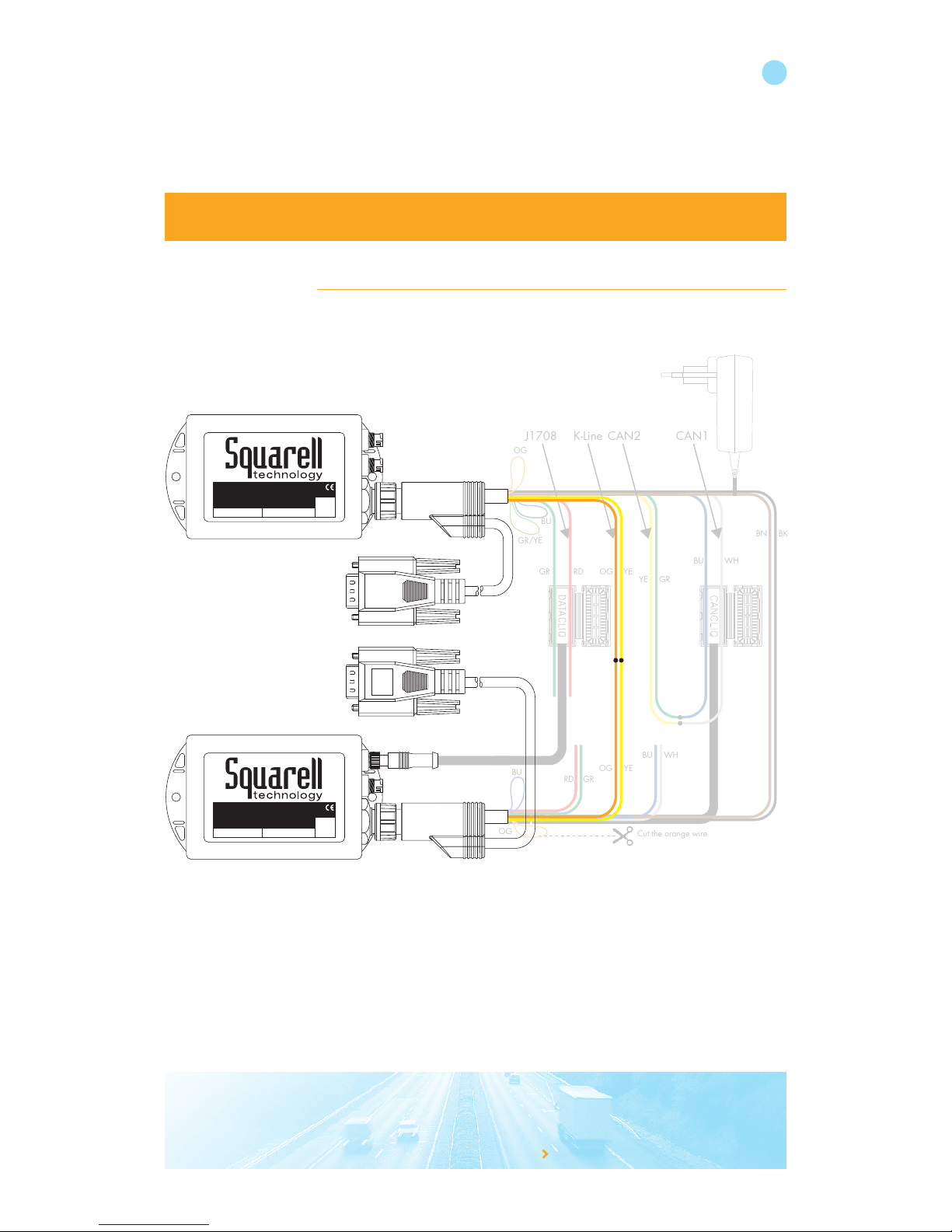
To test multiple signals besides the CANbus this setup should be made. The interface device is not sending tacho
data. You will not receive K-line data on iUpload.
20
BU
Cut the orange wire
BU WH
YE GR
OG YERDGR
RD GR
OG YE
BU WH
BN BK
BU
OG
GR/YE
J1708 K-Line CAN2 CAN1
DATACLIQ
OG
FLEX
Multi Source Vehicle Data Interface
S/N: 27197809Type: FLX12
12p SFD ASFD B
FLEX
Multi Source Vehicle Data Interface
S/N: 27197809Type: FLX12
12p SFD ASFD B
Test Device
Interface Device
To PC / Telematics Device
To PC which runs iConfigure
CANbus Monitor
280
Page 22

because you want to knowwww.squarell.com
7. What to do next?
After completing this manual you are able to:
• Understand output data
• Make a CANbus scan
• Make a J1708 scan
• Make a K-line scan
• Log in to Expertview
• Search a device in Expertview
• Change firmware and DCF in Expertview
• Start iUpload
• Update the device
• Create reports
• Connect to your telematics device
• Install the device in a vehicle (check support.squarell.com for vehicle installation instructions)
21
Page 23
because you want to knowwww.squarell.com
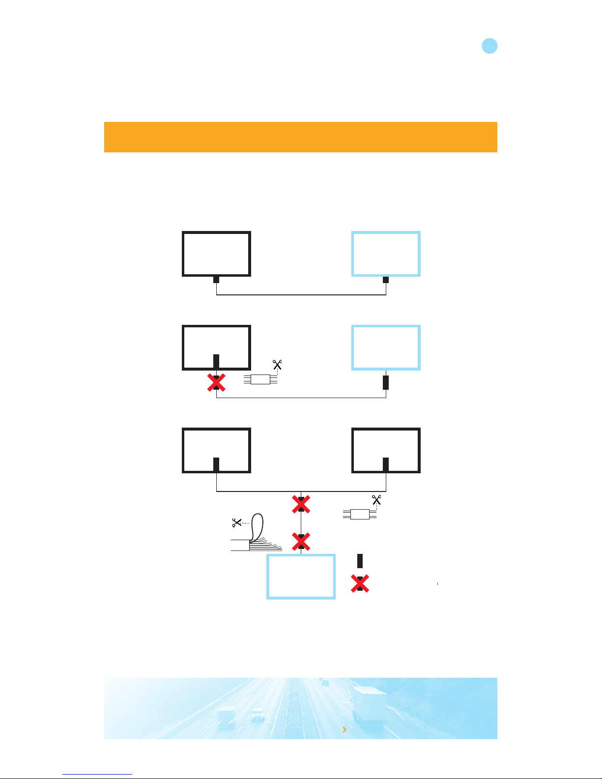
8. CANbus Termination
Terminate the CANbus always with 2 terminators.
All FLEX cables are equipped with 2 removable terminators on CANbus 1.
• Remove one terminators if the CANbus already is equipped with one terminator.
• Remove both cable terminators is the Squarell device becomes part of an existing (terminated) CANbus system.
Check the Termination:
• Turn Ignition off
• Power off
• Resistance between CAN High and CAN low must be 60 Ω
When the resistance is 40 Ω: The CANbus has 3 Terminators, remove one of the terminators.
When the resistance is 120 Ω: The CANbus has only 1 Terminator, add one terminator.
Modem CAN
input
Squarell FLEX
Squarell FLEX cable CAN1
Modem CAN
input
Squarell FLEX
Squarell FLEX cable CAN1
= Terminator
= Remove terminator
Modem CAN
input
Manufacturer
FMS
Squarell FLEX cable CAN1
Squarell FLEX
WH
BU
T
WH
BU
T
BU
22
Page 24

23
because you want to knowwww.squarell.com
9. Abbreviations and Terminology
In this manual there are abbreviations for the colors that are used in the Squarell products: The color abbreviations are:
BK = Black
BN = Brown
BU = Blue
GR = Green
OG = Orange
RD = Red
WH = White
YE = Yellow
Other abbreviations
CAN Controller Area Network
DAP Driver Awareness Panel
DCF Device Configuration File
SFD Special Function Device
MSB Most Significant Bit
LSB Least Significant Bit
Page 25

because you want to knowwww.squarell.com
10. Technical Support
If you need support from Squarell, you are welcome to visit our Squarell Support Portal (support.squarell.com). Here
we’ve built an extensive knowledgebase filled with user manuals, simulation setups, frequently asked questions and
many more downloads.
If you cannot find the answer you’re looking for, you can submit an online support ticket to our helpdesk. We will
review your query and come back with you with the answer you’re looking for. To use the Squarell Support Portal you
need to register for a user account first.
You can also submit a ticket if you need more help with choosing configurations, testing, installations or analysis. We
have configuration services available to help you with your projects.
Squarell Support Team
24
Page 26
because you want to knowwww.squarell.com
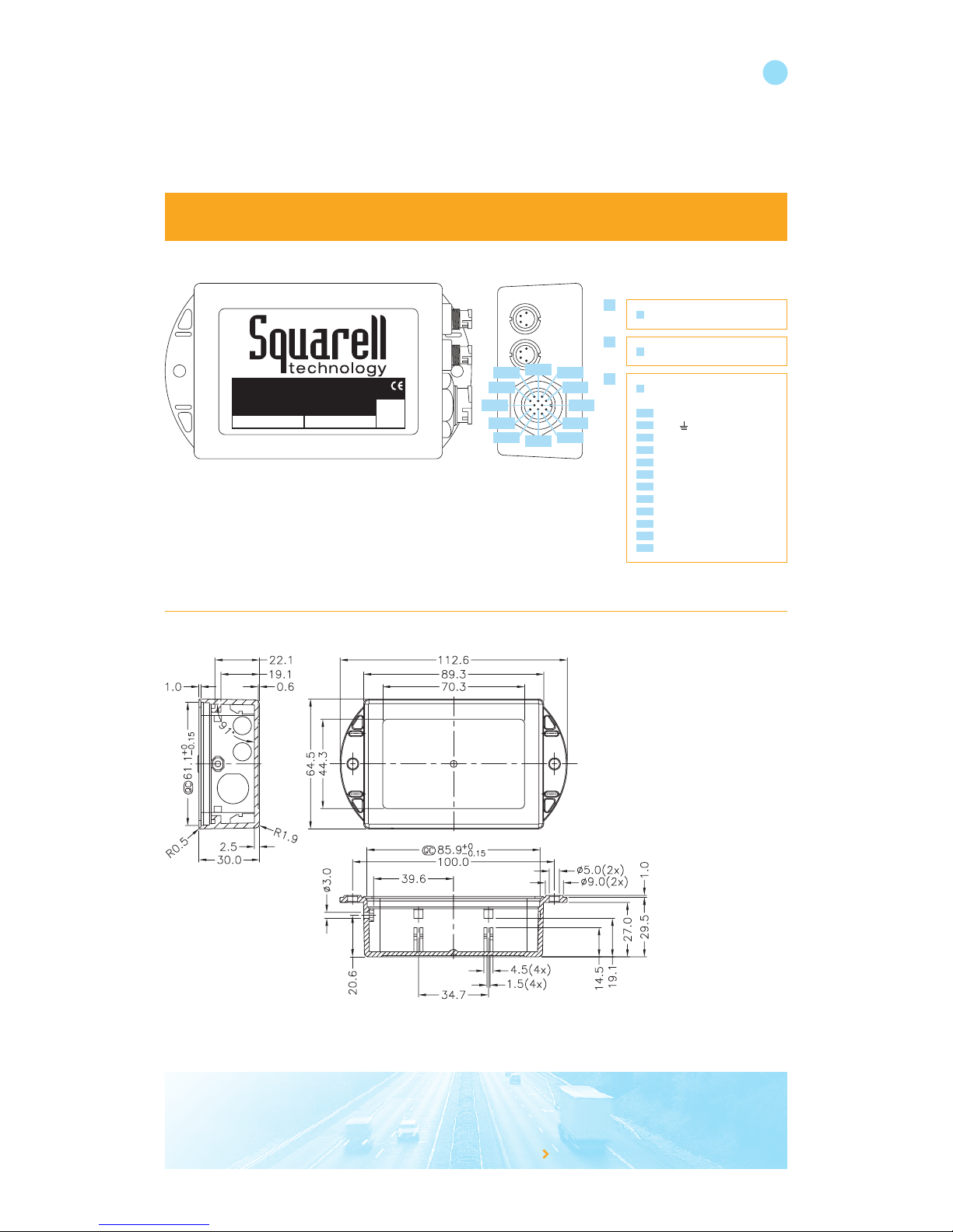
FLEX
Multi Source Vehicle Data Interface
S/N: 27197809Type: FLX12
12p SFD ASFD B
A
B
1
Pin 4
Pin 5
Pin 9Pin10
Pin 1
Pin 8
Pin 2
Pin 7
Pin 3
Pin 6
Pin11
Pin12
A
4-pole SFD connector
B
4-pole SFD connector
1
Universal 12-pole connector
Pin Function Color
Pin 1
V+ BN
Pin 2
Gnd BK
Pin 3
CAN1-H WH
Pin 4
CAN1-L BU
Pin 5
K-line 1 OG
Pin 6
K-Line 2 YE
Pin 7
J1708- GR
Pin 8
J1708+ RD
Pin 9
CAN2-H YE
Pin10
CAN2-L GR
Pin11
TXD (pin 2) RS232
Pin12
RXD (pin 3) RS232
25
Appendix
Page 27
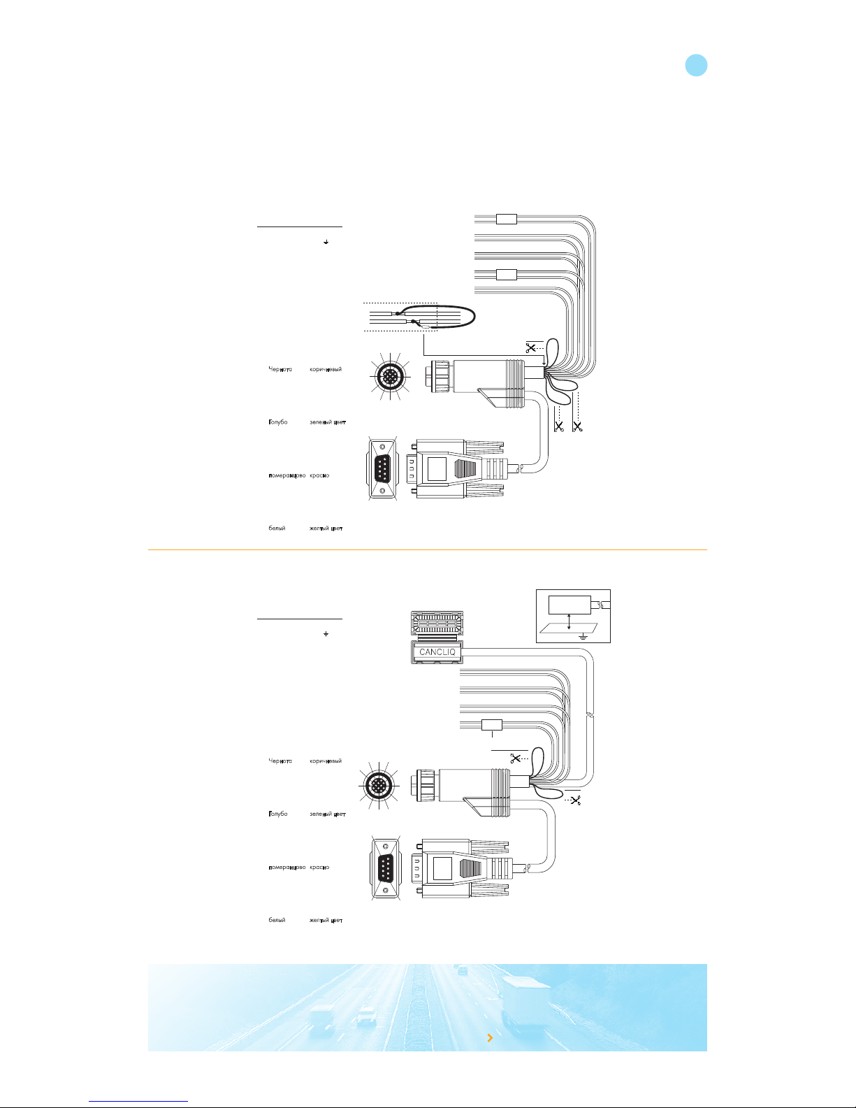
8612-U1 12-Pole universal Cable
8612-CQ 12-Pole Cable with CANcliQ
because you want to knowwww.squarell.com
Device: FLEXcliQ cable 12 pin
Connect to: FLEX
Ordercode: 8612 - CQ
Oude Weerlaan 27
2181 HX Hillegom
The Netherlands
t: +31 (0)252 - 42 03 11
www.squarell.com
Usage of this equipment is permitted for industrial purposes only. It must not be used
in situations in which human lives depend upon the operation of this equipment.
WH White
Wit
Weiss
Blanc
Blanco
Bianco
белый
YE Yellow
Geel
Gelb
Jaune
Amarillo
Giallo
желтый цвет
OG Orange
Oranje
Orange
Orange
Anaranjado
Alaranjado
померанцово
RD Red
Rood
Rot
Rouge
Rojo
Rosso
красно
BU Blue
Blauw
Blau
Bleu
Azul
Blu
Голубо
GR Green
Groen
Grün
Ver t
Verde
Verde
зеленый цвет
BK Black
Zwart
Schwarz
Noir
Negro
Nero
Чернота
BN Brown
Bruin
Braun
Brun
Marrón
Marrone
коричневый
8612CQP001
WH
BU
BU
OG
YE
OG
RD
GR
BK
1,5m
CANbus terminator
Cut the wire = no terminator
BN
6127
3112
1 4
8 5
9
9 5
6 1
10
Warning: Closes only once!
CANcliQ
> 5mm
T
K-line pull-up
resistor
Cut the wire
= no pull-up
resistor
T
12-Pole connector:
Pin Color Function
1 BN V+
2 BK Gnd
3 WH CAN1-H
4 BU CAN1-L
5 OG K-line 1
6 YE K-line 2
7 GR J17088 RD J1708+
9 BK CAN2-H
10 BK CAN2-L
11 BK TXD (pin 2)
12 BK RXD (pin 3)
CANcliQ
}
RS232
}
}
Female
Device: FLEX universal cable 12 pin
Connect to: FLEX
Ordercode: 8612 - U1
Oude Weerlaan 27
2181 HX Hillegom
The Netherlands
t: +31 (0)252 - 42 03 11
www.squarell.com
Usage of this equipment is permitted for industrial purposes only. It must not be used
in situations in which human lives depend upon the operation of this equipment.
WH White
Wit
Weiss
Blanc
Blanco
Bianco
белый
YE Yellow
Geel
Gelb
Jaune
Amarillo
Giallo
желтый цвет
OG Orange
Oranje
Orange
Orange
Anaranjado
Alaranjado
померанцово
RD Red
Rood
Rot
Rouge
Rojo
Rosso
красно
BU Blue
Blauw
Blau
Bleu
Azul
Blu
Голубо
GR Green
Groen
Grün
Ver t
Verde
Verde
зеленый цвет
BK Black
Zwart
Schwarz
Noir
Negro
Nero
Чернота
BN Brown
Bruin
Braun
Brun
Marrón
Marrone
коричневый
8612U1P001
6127
3112
1 4
8 5
9
9 5
6 1
10
OG
YE
BU
WH
BU
OG
GR / YE
RD
GR
BK
1,5m
CANbus terminator
Cut the wire = no terminator
Female
BN
GR
YE
K-line pull-up resistor
Cut the wire = no pull-up resistor
T
T
T
12-Pole connector:
Pin Color Function
1 BN V+
2 BK Gnd
3 WH CAN1-H
4 BU CAN1-L
5 OG K-line 1
6 YE K-line 2
7 GR J17088 RD J1708+
9 YE CAN2-H
10 GR CAN2-L
11 BK TXD (pin 2)
12 BK RXD (pin 3)
RS232
}
}
T
}
26
Page 28
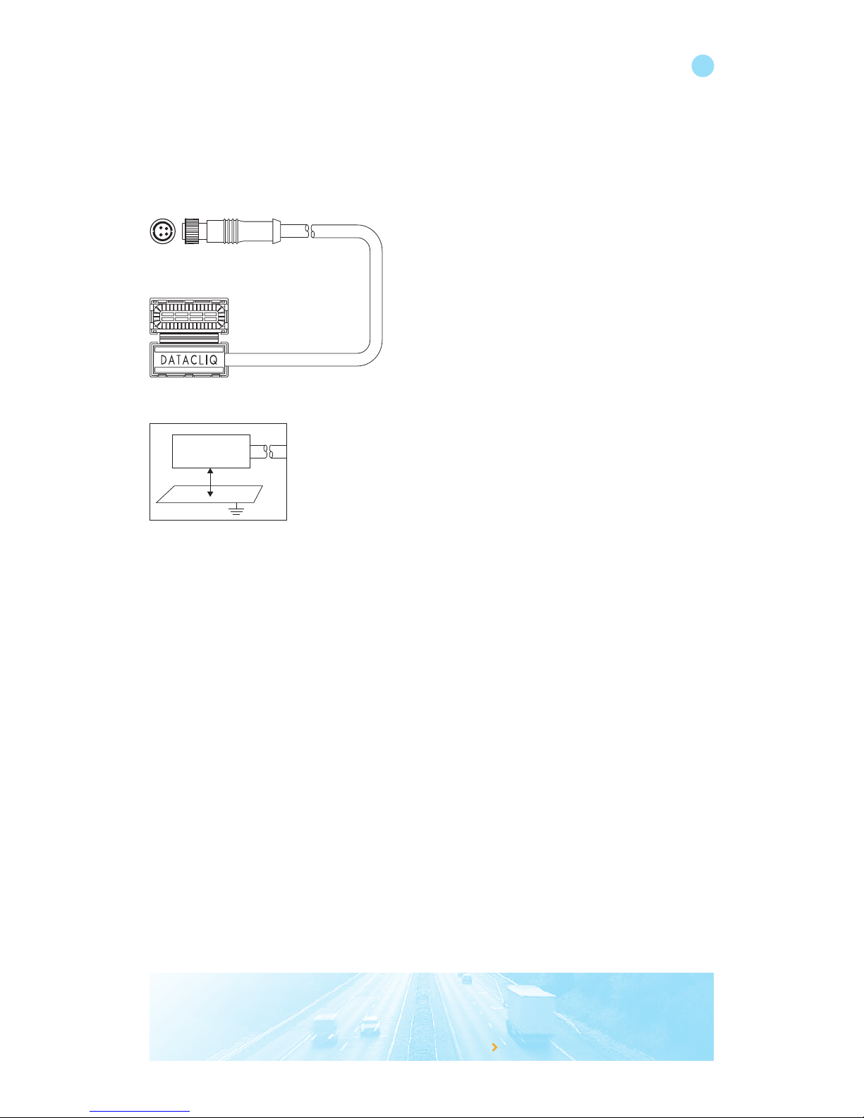
8510-XXX DatacliQ cable (optional)
because you want to knowwww.squarell.com
Ordercode: 8510 - XXX
Oude Weerlaan 27
2181 HX Hillegom
The Netherlands
t: +31 (0)252 - 42 03 11
www.squarell.com
DatacliQ
> 5mm
27
Page 29
because you want to knowwww.squarell.com
28
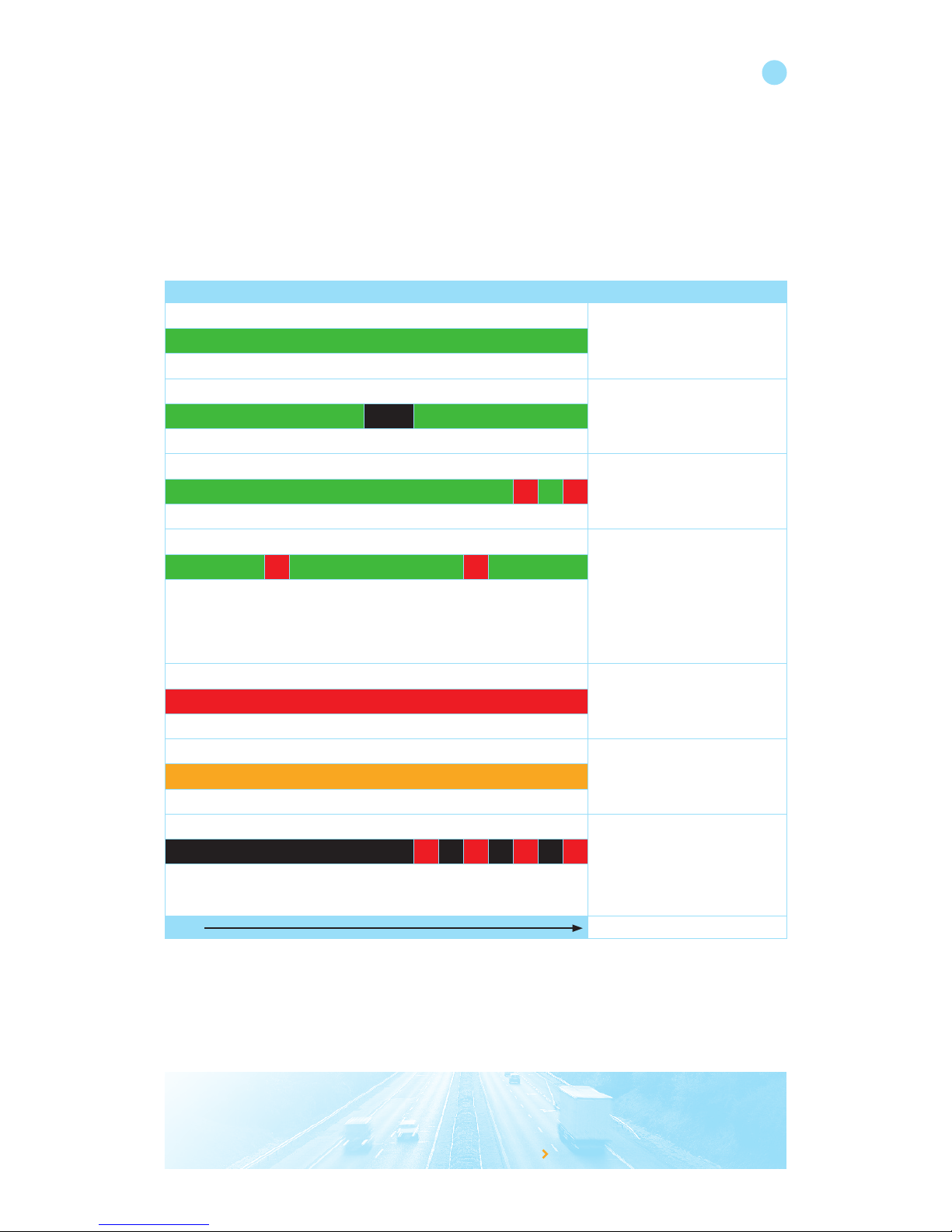
LED information
The FLEX (Squarell latest dcf version) is equipped with a status LED, with this LED you can check if the Squarell Device
is operational. The LED can light up green or red. The LED colours / patterns have the following meanings:
To test your vehicle CANbus connection:
After installation you can test the CANbus connection by turning the vehicle ignition ON and check the green LED
of the device. Now press the brake pedal and check if the green LED of the device blinks black once. If yes, your
CANbus connection is OK.
Led status
Device active. CANbus data is
being acknowledged.
Device is reading vehicle CANbus. Brake message received.
Device active. But no 1 of the
CANbus channels is stopped.
Check CANbus connection and
check the CANbus termination.
1 of the RS232 ports of the
Device is in interface mode:
• The device is uploading a DCF
to itself or to another device
• The device is downloading a
DCF to itself or to another device
• The device is monitoring the
CANbus
Device is not running a DCF:
• No DCF loaded or DCF corrupt
(reload DCF with iConfigure).
No valid “Key” loaded in the
device. DCF is not active.
When this LED patterns occurs
(2 to 6 red blinks) reload the
firmware and DCF.
When this LED patterns occurs
permanently, the device must be
send in for repair.
Time
Page 30

because you want to knowwww.squarell.com
Squarell Technology
Oude Weerlaan 27
2181 HX Hillegom
The Netherlands
Tel.: +31 (0)252 42 03 11
Fax: +31 (0)252 41 36 29
[email protected]
 Loading...