

User Manual: Squareled Vintage PAR Senior LED
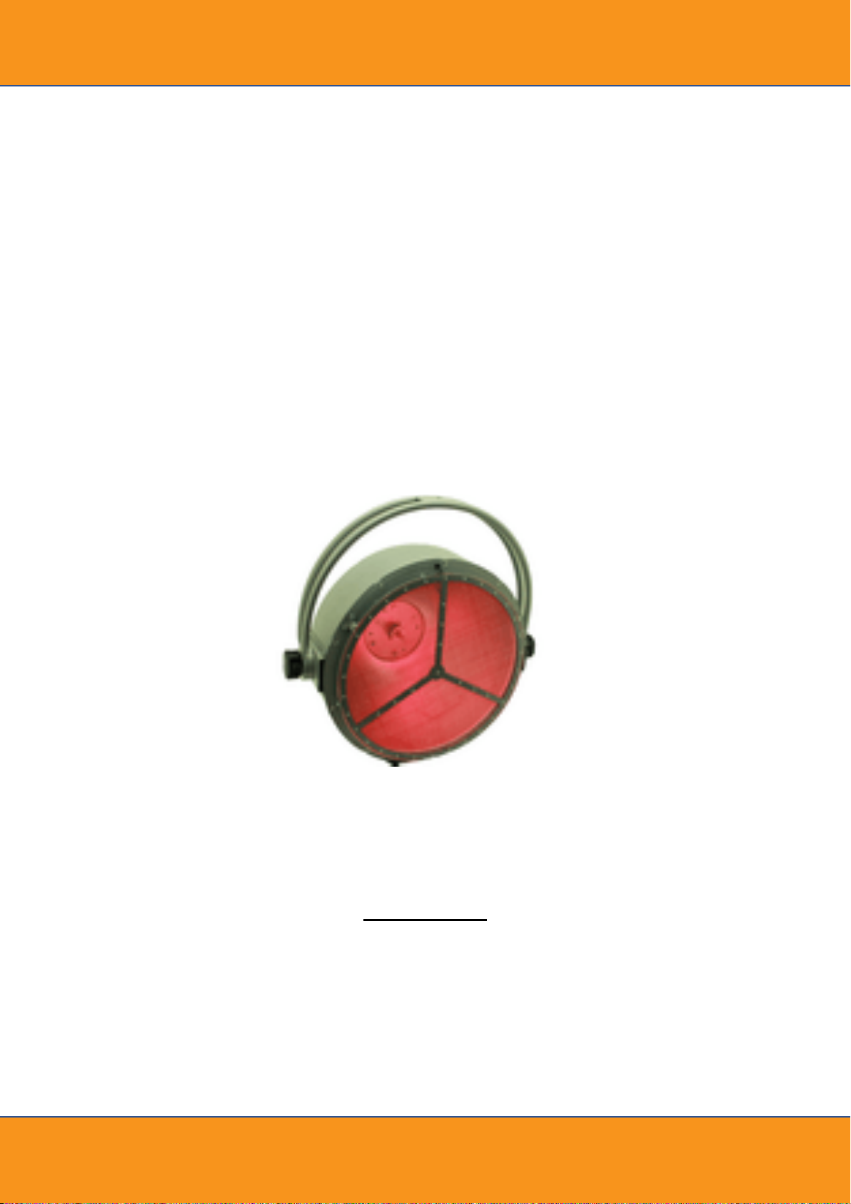
SQUARELED VINTAGE PAR
SENIOR - LED VERSION
Manual

DMX512 control
The wires must not come into contact with each other, otherwise the devices will not work at all, or will not
work properly. Please note, the starting address depends upon which controller is being used.
Only use a DMX-cable and 3-pin or 5-pin XLR plugs and connectors in order to connect the controller with
the device or one device with another.
If you are using controllers with this occupation, you can connect the DMX output of the controller directly
with the DMX input of the first device in the DMX chain. If you wish to connect DMX controllers with other
XLR outputs, you need to use adapter cables.
Building a serial DMX chain:
Connect the DMX output of the first device in the DMX chain with the DMX input of the next device.
Always connect one output with the input of the next device until all devices are connected.
Caution: At the last fixture, the DMX-cable has to be terminated. Plug the terminator with a 120Ω resistor
between Signal (–) and Signal (+) in the DMX-output of the last fixture.
Interconnecting several devices (master/slave operation)
Several devices may be interconnected (max. 30). Then all slave units can be synchronized and controlled
with the master unit without the need for a DMX controller. The devices must be set to the corresponding
operating modes.
Connect the DMX output of the master unit to the DMX input of the first slave unit. Then connect the DMX
output of the first slave unit to the DMX input of the second slave unit, etc. until all units have been
connected in a chain. Make sure the master unit is the first in the chain. Do not connect a DMX controller
to the DMX input of the master unit.
Set the master device to one of the stand-alone modes.
Set each slave device to any DMX address. The devices set in this manner can now be controlled by the
master unit.
Connection to the mains
1 Connect the device via the enclosed mains cable to a grounded mains socket. Thus, the unit is switched
on.
2 To switch off the unit, disconnect the power plug.
3 Do not connect the unit to the mains voltage via a dimmer. For a more convenient operation, use a mains
outlet which is switchable.
Power supply of further devices
The Jack POWER OUT allows for power supply of further devices. To interconnect several devices, connect
the Jack POWER OUT to the input POWER IN of the next unit until all units are connected. Matching power
cables with Power-Con plugs are available as accessories. In this manner, up to 3 devices can be linked at
230/240 input voltage.

Mode
Display
Function
ADDRESS
& DMX
Address 001-512
Setting DMX starting address
DMX-Model 1ch
Setting DMX channel mode
DMX-Model 2ch
DMX-Model 4ch
DMX-Model 7ch
MANUAL
Manual Halog 0 ~
255
Manual setting of the halogen lamp
Manual Red 0 ~ 255
Manual setting of the red LEDs
Manual Green 0 ~
255
Manual setting of the green LEDs
Manual Blue 0 ~ 255
Manual setting of the blue LEDs
STATIC1
Macro 1 ~ Macro 35
Manual setting of the color presets
DIMMERCURVES
Halogen
DimCurve Linear
Light intensity increases in-line with the DMX value
DimCurve Square
Light intensity increases exponentially with the DMX value
DimCurve InvSquare
Light intensity increases reverse exponentially with the DMX
value
DimCurve S-curve
Light intensity increases S-shaped with the DMX value
DIMMERCURVES
LED
LEDCurve Linear
Light intensity increases in-line with the DMX value
LEDCurve Square
Light intensity increases exponentially with the DMX value
LEDCurve InvSquare
Light intensity increases reverse exponentially with the DMX
value
LEDCurve S-curve
Light intensity increases S-shaped with the DMX value
OPERATION
After connecting the device to the mains it is ready for operation. The display indicates the last operating
mode. The operating modes can be selected by means of the display and the control buttons. All settings
remain stored even if the device is disconnected from the mains. The device can be operated in
stand-alone mode via the control board or in DMX-controlled mode via any commercial DMX controller.
Stand-alone mode
In the stand-alone mode, the device can be used without controller. Disconnect the device from the
controller.
Operating buttons
MENU Selects the operating mode or returns to the initial screen.
UP Selects the next menu item or increases values when modifying.
DOWN Selects the previous menu item or decreases values when modifying.
Menu structure in Stand Alone Mode

Channel
Value
Function
DIMMER, Halogen lamp
000 – 255
Brightness 0-100%
Manual dimmer intensity
Press the MENU button to select the manual dimmer intensity (Manual).
You can select the dimmer intensity of the halogen lamp (Manual Halog) as well as of the LEDs (Manual
Red/Green/Blue).
You can select the desired brightness values 000 -255 via the UP or DOWN button.
Please press the MENU button to exit the Mode.
Color presets
Press the MENU button to select the color presets (Static1).
You can select the desired color (Macro 1 ~ Macro 35) via the UP or DOWN button.
Please press the MENU button to exit the Mode.
Dimmer curves:
In order to set the dimmer curves for the halogen lamp, press the MENU button until the display shows
DimCurve. You can select the desired dimmer curve (Linear, Square, InvSquare,S-curve) via the UP or
DOWN buttons.
In order to set the dimmer curves for the LEDs, press the MENU button until the display shows LEDCurve.
You can select the desired dimmer curve (Linear, Square, InvSquare,S-curve) via the UP or DOWN buttons.
DMX operation
Setting the number of DMX channels and the DMX starting address
For operation with a controller with DMX512 protocol, the device is equipped with 7 control channels.
However, it can also be switched to a mode with 1, 2 or 4 channels if different functions are required. To be
able to operate the device with a DMX controller, the DMX starting address must be set. The starting
address depends upon which DMX controller is being used. Please refer to the controller’s documentation.
1, Press the MENU button so many times until DMX Address is indicated on the display.
2, Set the address via the UP and DOWN buttons and press the MENU button to return to the main menu.
3, Now press the MENU button so many times until DMX-Mode is indicated on the display.
4, The display then indicates 1CH (1 DMX channel), 2CH (2 DMX channels), 4CH (4 DMX channels) or 7CH (7
DMX channels). Use the buttons UP and DOWN to select the desired number of DMX channels. Please
press the MENU button to return to the main menu.
5, The DMX address will be shown on the LCD when DMX signals are being received. If no control signals
are available, the DMX address and “No DMX Signal” will appear alternately on the display. Note: Please
make sure that you do not have any overlapping channels in order to control each device correctly and
independently from any other fixture on the DMX chain. If several devices are addressed similarly, they will
work synchronically.
Functions in DMX mode
1-Channel-Mode

Channel
Value
Function
1 DIMMER, Halogen
lamp
000 – 255
Brightness 0-100%
2 COLOR
PRESETS LEDs
2 COLOR
PRESETS LEDs
000 – 004
No function
005 – 011
Color 1
012 – 018
Color 2
019 – 025
Color 3
026 – 032
Color 4
033 – 039
Color 5
040 – 046
Color 6
047 – 053
Color 7
054 – 060
Color 8
061 – 067
Color 9
068 – 074
Color 10
075 – 081
Color 11
082 – 088
Color 12
089 – 095
Color 13
096 – 102
Color 14
103 – 109
Color 15
110 – 116
Color 16
117 – 123
Color 17
124 – 130
Color 18
131 – 137
Color 19
138 – 144
Color 20
145 – 151
Color 21
152 – 158
Color 22
159 – 165
Color 23
166 – 172
Color 24
173 – 179
Color 25
180 – 186
Color 26
187 – 193
Color 27
194 – 200
Color 28
201 – 207
Color 29
208 – 214
Color 30
215 – 221
Color 31
222 – 227
Color 32
228 – 234
Color 33
235 – 241
Color 34
242 – 255
Color 35
2-Channel-Mode

Channel
Value
Function
1 DIMMER, Halogen
lamp
000 – 255
Brightness 0-100%
2 DIMMER, RED LEDs
000 – 255
Brightness 0-100%
3 DIMMER, Green LEDs
000 – 255
Brightness 0-100%
4 DIMMER, Blue LEDs
000 – 255
Brightness 0-100%
Channel
Value
Function
1 DIMMER, Halogen
lamp
000 – 255
Brightness 0-100%
2 DIMMER, RED LEDs
000 – 255
Brightness 0-100%
3 DIMMER, Green LEDs
000 – 255
Brightness 0-100%
4 DIMMER, Blue LEDs
000 – 255
Brightness 0-100%
5 Strobe
LED strips
000 – 003
No function
004 – 255
Increasing speed
6 DIMMER, ALL LEDs
000 – 255
Brightness 0-100%
7 COLOR
PRESETS LEDs
000 – 004
No function
005 – 011
Color 1
012 – 018
Color 2
019 – 025
Color 3
026 – 032
Color 4
033 – 039
Color 5
040 – 046
Color 6
047 – 053
Color 7
054 – 060
Color 8
061 – 067
Color 9
068 – 074
Color 10
075 – 081
Color 11
082 – 088
Color 12
089 – 095
Color 13
096 – 102
Color 14
103 – 109
Color 15
110 – 116
Color 16
117 – 123
Color 17
124 – 130
Color 18
131 – 137
Color 19
138 – 144
Color 20
145 – 151
Color 21
152 – 158
Color 22
4-Channel-Mode
7-Channel-Mode

7 COLOR
PRESETS LEDs
159 – 165
Color 23
166 – 172
Color 24
173 – 179
Color 25
180 – 186
Color 26
187 – 193
Color 27
194 – 200
Color 28
201 – 207
Color 29
208 – 214
Color 30
215 – 221
Color 31
222 – 227
Color 32
228 – 234
Color 33
235 – 241
Color 34
242 – 255
Color 35
TECHNICAL SPECIFICATIONS:
Power supply: 230 V AC, 50 Hz ~
Power consumption: 780 W Max
Protection class: I
DMX control channels: 1/2/4/7
DMX512 connection: 5-pin and 3-pin XLR
Flash-rate: 20 Hz
Lamp number: 1
Lamp type: HPL 230V/750W GX9.5 or HPL 230V/575W GX9.5
LED number: 27
LED type: 0.5 W RGB 5050 SMD
Dimensions (LxWxH): 365 x 705 x 640 mm
Weight: 11 kg
Vintage PAT-504
Power supply: 230 V AC, 50 Hz ~
Power consumption: 530 W Max
Protection class: I
DMX control channels: 1/2/4/7
DMX512 connection: 5-pin and 3-pin XLR
Flash-rate: 20 Hz
Lamp number: 1
Lamp type: 230V/500W GY9.5 or 230V/300W GY9.5
LED number: 18
LED type: 0.5 W RGB 5050 SMD
Dimensions (LxWxH): 265 x 540 x 460 mm
Weight: 9 kg

Das Lichttechnikhaus Vertriebs GmbH
Rudolf-Diesel-Str. 3, D-89312 Günzburg
Telefon +49 (0) 82 21 207 98-0
Fax +49 (0) 82 21 207 98-69
E-Mail info@lth-gmbh.de
Web www.lth-gmbh.de
 Loading...