

Page 1

SquareLED - Storm1000
Page 2

Manual | Storm1000
1. GETTING STARTED
Unpacking
• 1 x Storm1000 RGBW LED Strobe
• 1 x Base Plate
• A Sweet Safety Cable, An Eyebolt & Set of Mounting Brackets
• An Ever-So-Handy Power Cord
• This Lovely User Manual
Carefully check the shipping carton for damage that may have occurred during shipping. If the carton appears to be damaged, carefully inspect your unit for damage and be sure all accessories necessary to operate
the unit have arrived intact. In the event damage has been found or parts are missing, please
contact our customer support team for further instructions. Please do not return this unit to your dealer without rst contacting customer support at the number listed below.
Introduction
Congratulations, you have just purchased one of the most innovative
and reliable lighting xtures on the market today! Please read and understand the instructions in this manual
carefully and thoroughly before attempting to operate this unit, This manual contains important information
regarding safety protocol that must be strictly adhered to at all times.
Powering Up
All xtures must be powered directly o a switched circuit and cannot be run o a rheostat (variable resistor) or dimmer circuit, even if the rheostat or dimmer channel is used solely for a 0% to 100% switch.
AC Voltage Switch - Not all xtures have a voltage select switch, so please verify that the xture you receive is
suitable for your local power supply. See the label on the xture or refer to the xture’s specications chart for
more information. A xture’s listed current rating is its average current draw under normal conditions. Check
the xture or device carefully to make sure that if a voltage selection switch exists that it is set to the correct
line voltage you will use.
Warning! Verify that the voltage select switch on your unit matches the line voltage applied. Damage
to your xture may result if the line voltage applied does not match the voltage indicated on the voltage selector switch. All xtures must be connected to circuits with a suitable Ground (Earthing).
Getting A Hold Of Us
If something is wrong, please contact your dealer.
Disclaimer: The information and specications contained in this document are subject to change without no-
tice. We assumes no responsibility or liability for any errors or omissions that may appear in this user manual.
We reserves the right to update the existing document or to create a new document to correct any errors or
omissions at any time. You can get the latest version of this document from your dealer.
Page 3

Manual | Storm1000
Please read these instructions carefully
SAFETY INSTRUCTIONS
they include the important information
about the installation usage and
maintenance of this products
Please note:
to ashing or strobe lighting. If strobe lighting is to be used in a production, warnings should be
posted at the front of house or entrance doors to the theater as well as in a program, if distributed.
Example: “WARNING: Strobe lights are used during this performance.”
• Please keep this User Guide for future use. If you sell the unit to someone else, be sure that they also
receive this User Guide.
• ALWAYS make sure that you are connecting to the proper voltage, and that the line voltage you are con-
necting to is not higher than that stated on the decal or rear panel of the xture.
• Make sure there are no ammable materials close to the unit while operating.
• The unit must be installed in a location with adequate ventilation, at least 20in (50cm) from adjacent
surfaces. Be sure that no ventilation slots are blocked.
• ALWAYS disconnect from the power source before servicing or replacing fuse and be sure to replace with
same fuse size and type.
• ALWAYS secure xture using a safety chain. NEVER carry the xture by its cord. Use its carrying handles.
• DO NOT operate at ambient temperatures higher than 104°F (40°C).
• In the event of a serious operating problem, stop using the unit immediately. NEVER try to repair the unit
by yourself. Repairs carried out by unskilled people can lead to damage or malfunction. Please contact the
nearest authorized technical assistance center. Always use the same type spare parts.
• NEVER connect the device to a dimmer pack.
• Make sure the power cord is never crimped or damaged.
• Never disconnect the power cord by pulling or tugging on the cord.
• Avoid direct eye exposure to the light source while it is on.
Certain people with epilepsy and photosensitivity may suer a seizure if exposed
Caution!
There are no user serviceable parts inside the unit. Do not open the housing or attempt any repairs yourself.
In the unlikely event your unit may require service, please call your dealer.
Page 4
Manual | Storm1000
2. MEET Storm1000 RGBW LED STROBE FIXTURE
MAIN FEATURES
• Super bright output via 1260 0.8w RGBW LEDs
• Intense built-in strobe programs + random strobe
• 2-segment pixel modes can safely be used as wash (max 40% brightness)
• Built-in over heat protection temperature sensor to extend the lamp life
• Variable electronic strobe & 16-bit dimmer
• User adjustable ash rate of 0-30 ashes per second
• Flash duration can be set from 0-650ms in DMX mode
• 7000Hz LED scan rate
• 4-button easy to use LCD control panel menu
• Aluminum mounting bracket with locking knobs + base plate
• 3-pin & 5-pin DMX Input/Output
• PowerCon™ compatible AC power In/Out connectors
• Never disconnect the power cord by pulling or tugging on the cord.
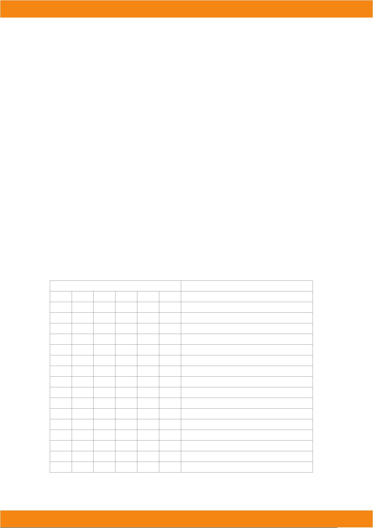
DMX Quick Reference (1/3/4/7/8/16-Channel Modes)
Channel Mode
1 3
------ 1
------ ------ ------
------ ------ ------
------ ------ ------
------ ------ ------
------ 2
1 3
------ ------
------ ------ ------ ------ ------
------ ------ ------ ------ ------
------ ------ ------ ------ ------
------ ------ ------ ------ ------
------ ------ ------ ------ ------
------ ------ ------ ------ ------
------ ------ ------ ------ ------
------ ------ ------ ------ ------
4 7 8 16
1 1 1 1 Master Dimmer (0-100%)
2 2 2 Red segment Intensity (0-100%)
3 3 3 Green segment Intensity (0-100%)
4 4 4 Blue segment Intensity (0-100%)
5 5 5 White segment Intensity(0-100%)
2 6 6 6 Flash duration (0-full on)
3 7 7 7 Strobe rate (0-30Hz)
------
4
8 8 Built-In Eects
Function
9 Red1/Segment 1 Intensity (0-100%)
10 Green1/Segment 2 Intensity (0-100%)
11 Blue1/Segment 3 Intensity (0-100%)
12 White1/Segment 4 Intensity (0-100%)
13 Red2/Segment 5 Intensity (0-100%)
14 Green2/Segment 6 Intensity (0-100%)
15 Blue2/Segment 7 Intensity (0-100%)
16 White2/Segment 8 Intensity (0-100%)
Page 5
Manual | Storm1000
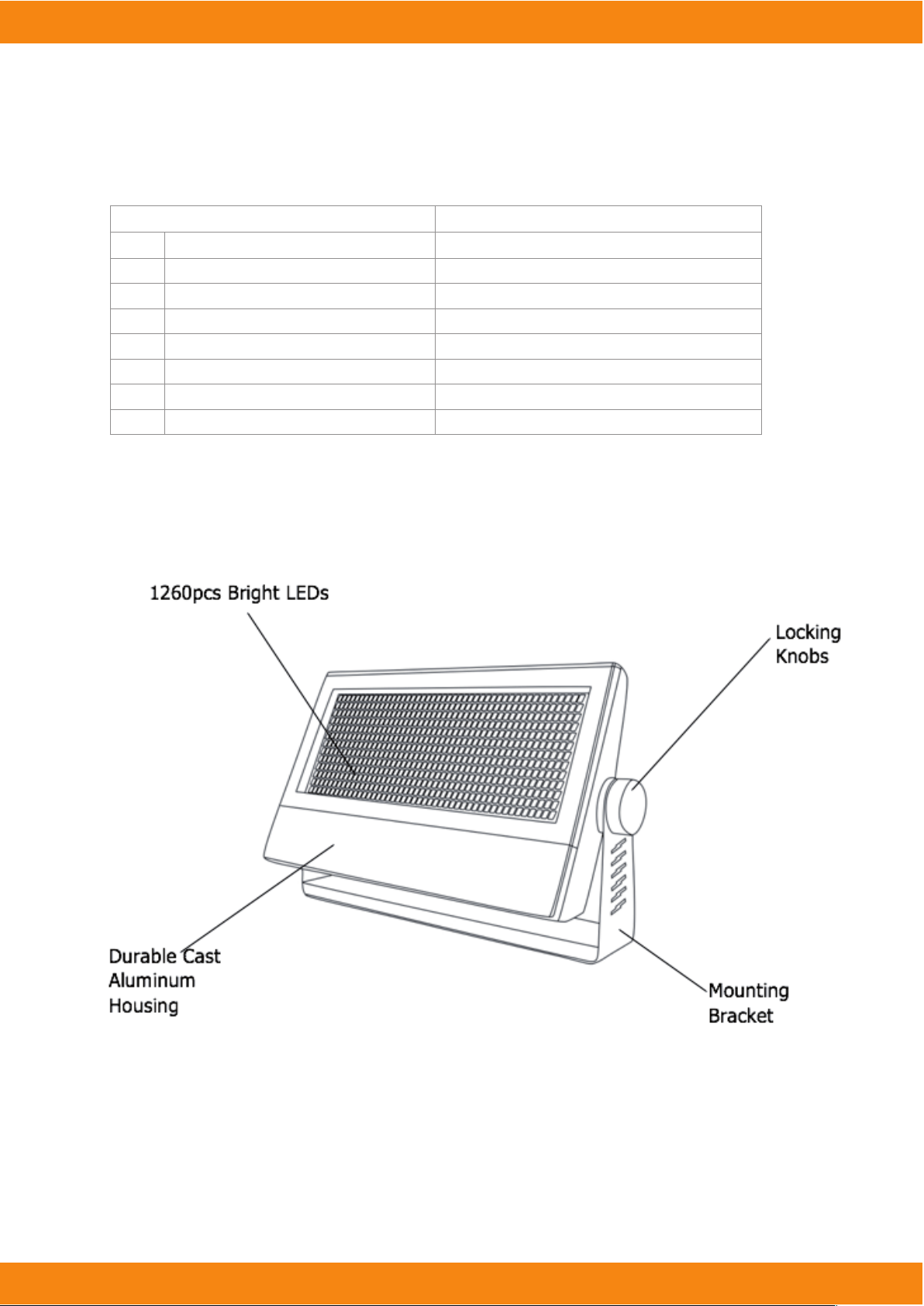
DMX Quick Reference (4/8-Channel: Pixel Modes)
4-Channel Pixel Mode
1 Red Segment Intensity (0-100%) Red1 Intensity (0-100%)
2 Green Segment Intensity (0-100%) Green1 Intensity (0-100%)
3 Blue Segment Intensity (0-100%) Blue1 Intensity (0-100%)
4 White Segment Intensity (0-100%) White1 Intensity (0-100%)
5 Red2 Intensity (0-100%)
6 Green2 Intensity (0-100%)
7 Blue2 Intensity (0-100%)
8 White2 Intensity (0-100%)
8-Channel Pixel Mode
Figure 1: The Storm1000 RGBW Pin-Up Picture
Page 6
Manual | Storm1000
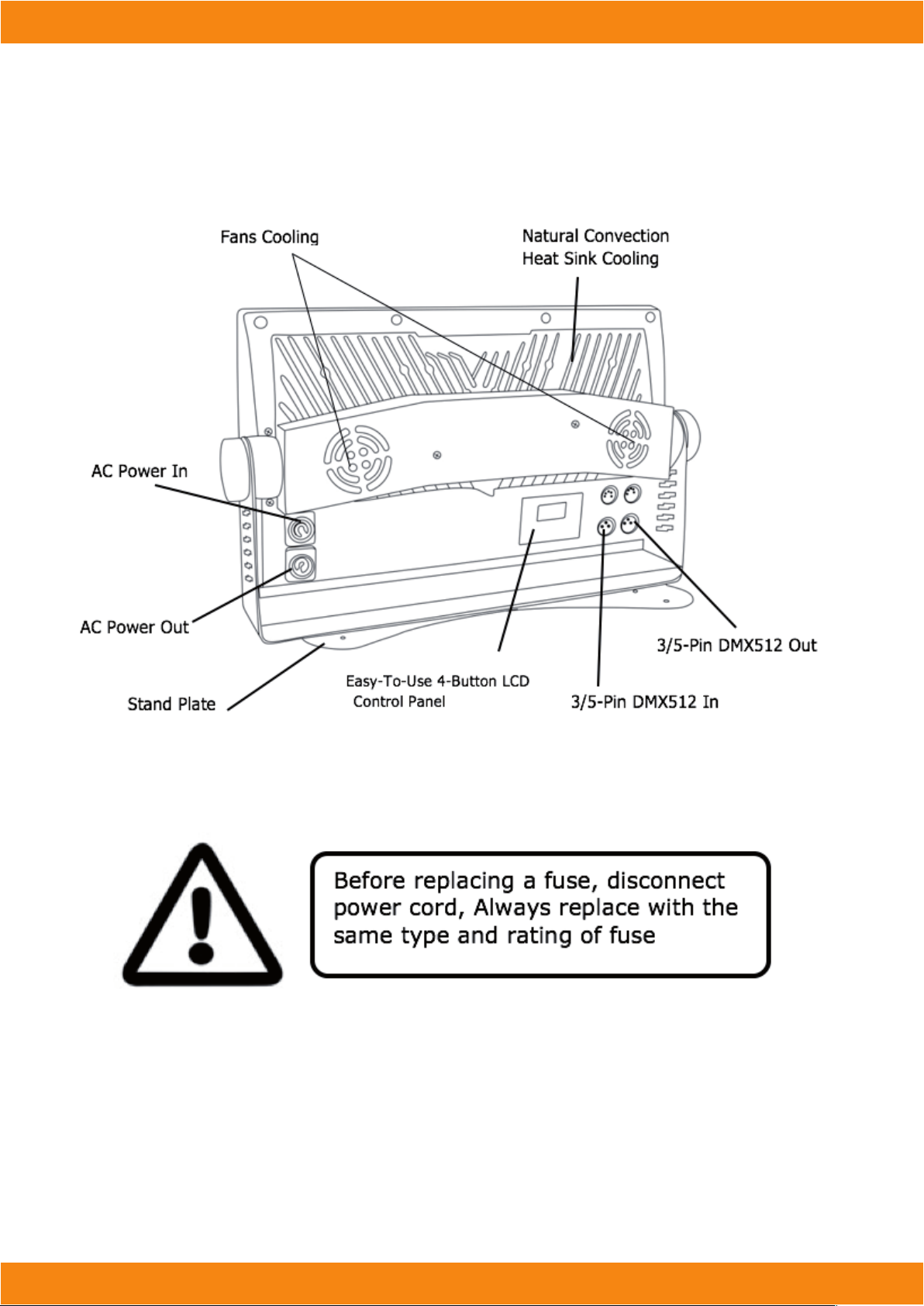
Figure 2: The Rear Connections
3. SETUP
Fuse Replacement
CAUTION! The Storm1000 RGBW utilizes a high-output switch-mode power supply with an internal fuse. Under normal operating conditions, the fuse should not require replacement. The fuse is
eld replaceable,however it is an advanced procedure suited to qualied individuals. Should your
Storm1000 RGBW fuse require replacement, please contact your dealer for instructions.
Page 7
Manual | Storm1000
Connecting A Bunch of Storm1000 RGBW Fixtures:
Follow the guide below to properly link xtures. Power the rst xture in the chain with a standard cable
(provided with xture). Then jump each subsequent xture with a properly rated jumper cable.
WARNING:
DO NOT POWER LINK MORE THAN (2) FIXTURES IN ONE SINGLE CHAIN, ELECTRICALOVERLOAD MAY OCCUR.
Data/DMX Cabling
To link xtures together you’ll need data cables. You should use data grade cables that can carry a high quality signal and are less prone to electromagnetic interference. For instance, Belden© 9841 meets the specications for EIA RS-485 applications. Standard microphone cables will “probably” be OK, but note that they
cannot transmit DMX data as reliably over long distances. In any event, the cable should have the following
characteristics:
2-conductor twisted pair plus a shield
Maximum capacitance between conductors – 30 pF/ft.
Maximum capacitance between conductor & shield – 55 pF/ft.
Maximum resistance of 20 ohms / 1000 ft.
Nominal impedance 100 – 140 ohms
Cable Connectors
Cables must have a male XLR connector on one end and a female XLR connector on the other end. (Duh!)
A Word on Termination: DMX is a resilient communication protocol, however errors still occasionally occur.
Termination reduces signal errors, and therefore best practices include use of terminator in all circumstances.
If you experiencing problems with erratic xture behavior, especially over long cable runs, a terminator may
help improve performance.
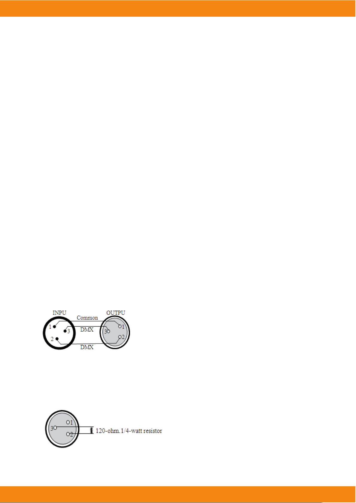
To build your own DMX Terminator: Obtain a 120-ohm, 1/4-watt resistor, and wire it between pins 2 & 3 of
the last xture. They are also readily available from specialty retailers.
Page 8
Manual | Storm1000
CAUTION: Do not allow contact between the common and the xture’s chassis ground. Grounding the
common can cause a ground loop, and your xture may perform erratically. Test cables with an ohm
meter to verify correct polarity and to make sure the pins are not grounded or shorted to the shield or
each other.
3-Pin / 5-Pin
If you use a controller with a 5 pin DMX output connector, you will need to use a 5 pin to 3 pin adapter.
They are widely available over the internet and from specialty retailers If you’d like to build your own,
the chart below details a proper cable conversion:
Conductor
Ground/Shield
DMX Data (-)
DMX Data (+)
Not Used. No Connection.
Not Used. No Connection
3-Pin Female(Output) 5-Pin Male(Input)
Pin 1 Pin 1
Pin 2 Pin 2
Pin 3 Pin 3
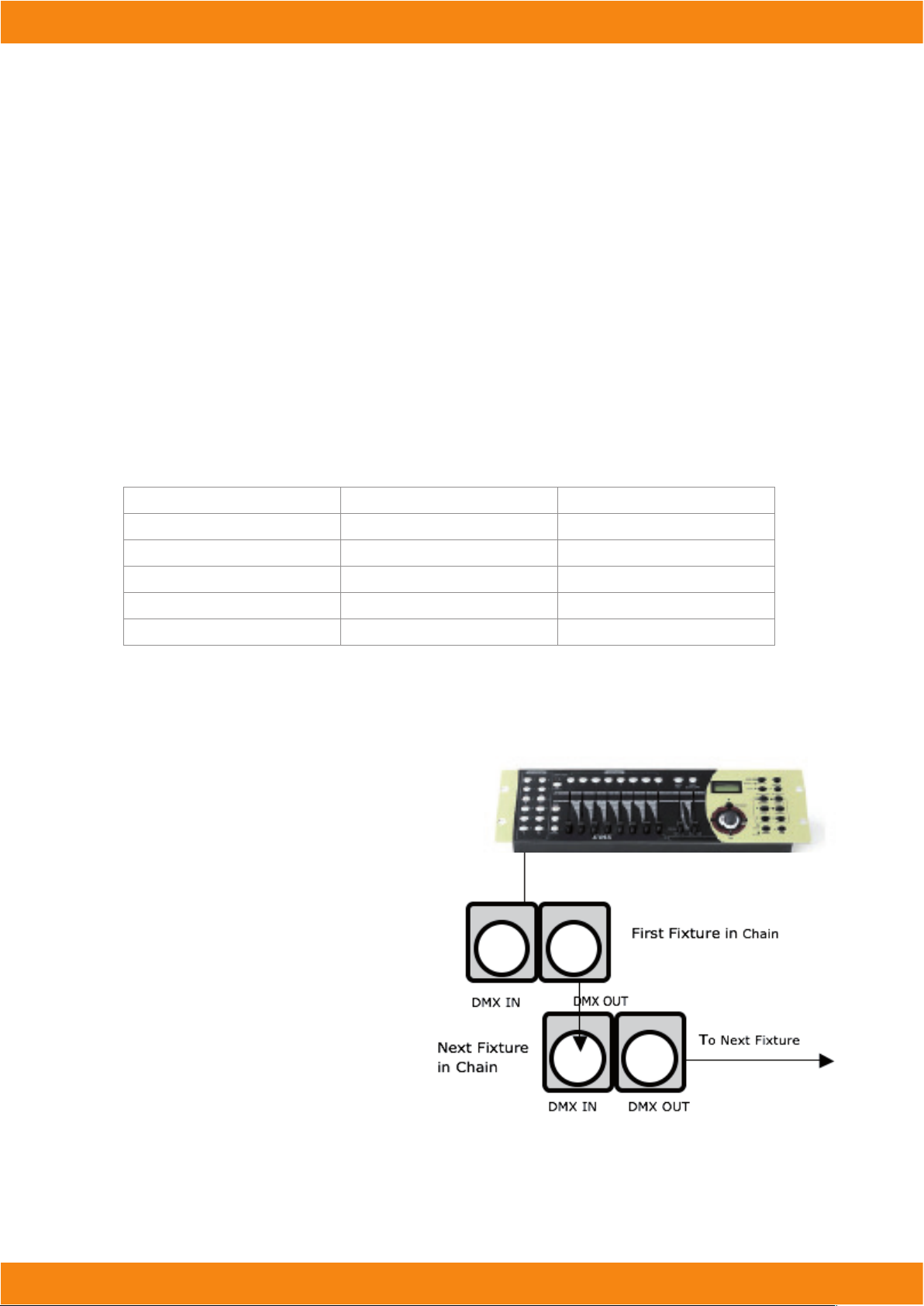
Take It To The Next Level: Setting Up DMX Control
Step 1: Connect the male connector of the
DMX cable to the female connector (output)
on the controller
Step 2: Connect the female connector of the
DMX cable to the rst xture’s male connector
(input). Note: It doesn’t matter which xture
address is the rst one connected. We recommend connecting the xtures in terms of
their proximity to the controller, rather than
connecting the lowest xture number rst,
and so on.
No Connection
No Connection
Step 3: Connect other xtures in the chain
from output to input as above. Place a DMX
terminator on the output of the nal xture
to ensure best communication.
Page 9
Manual | Storm1000
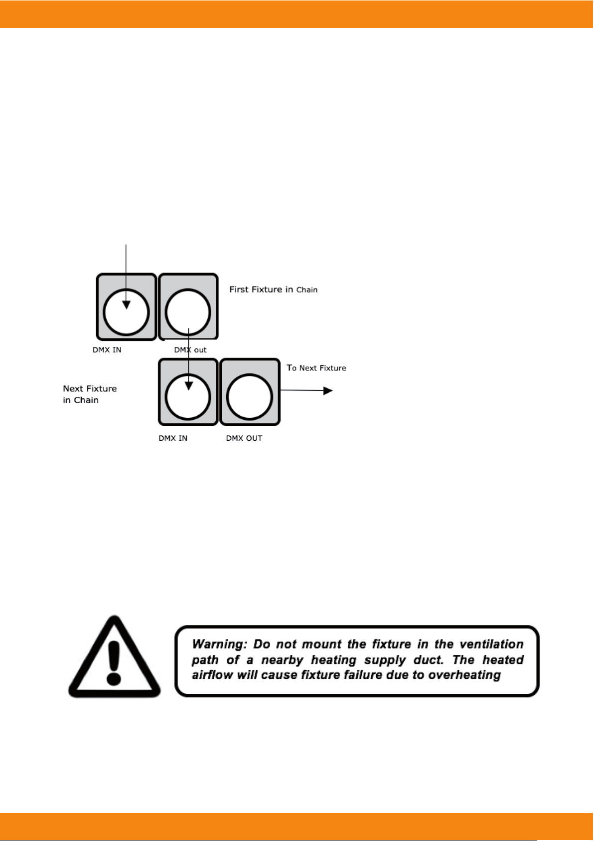
Fixture Linking (Master/Slave Mode)
1. Connect the (male) 3 pin connector side of the DMX cable to the output (female) 3 pin connector of the
rst xture.
2. Connect the end of the cable coming from the rst xture which will have a (female) 3 pin connector to the
input connector of the next xture consisting of a (male) 3 pin connector. Then, proceed to connect from the
output as stated above to the input of the following xture and so on.#
A quick note: Often, the setup for
Master-Slave and Standalone operation
requires that the rst xture in the
chain be initialized for this purpose via
either settings in the control panel or
DIP-switches. Secondarily, the xtures
that follow may also require a slave
setting.
Check the “Operating Adjustments”
section in this manual for complete
instructions for this type of setup and
conguration.
Mounting & Rigging
This xture can be mounted in any orientation (vertical, horizontal). Always make sure there is adequate
ventilation and no ammable surfaces within 2 feet (.6 meters) of the xture.
You can mount the xture using xture clamps or with threaded bolt type hardware. Always install the
included safety eyebolt and cable when mounting in overhead or wall locations.
.
Page 10
Manual | Storm1000
LEDSTROBE
ESC
DOWN
UP
ENTER
4. OPERATING ADJUSTMENTS
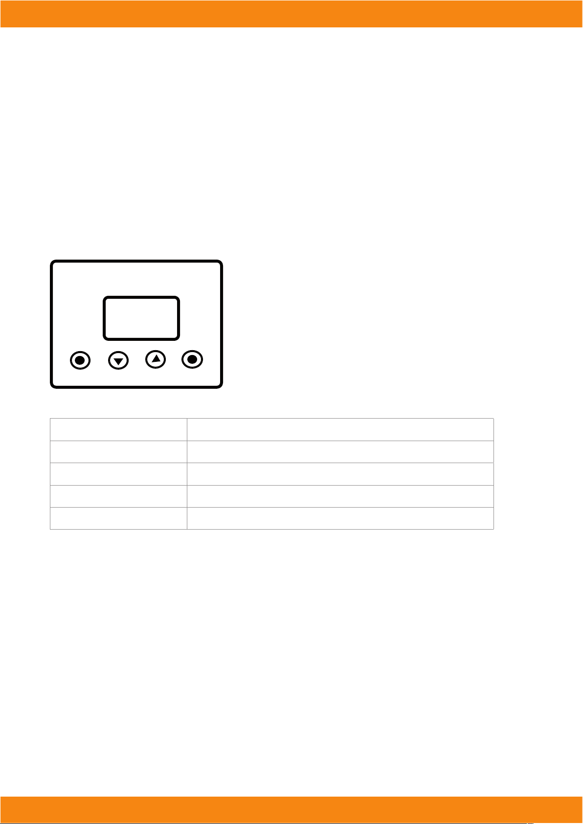
The Control Panel
All the goodies and dierent modes possible with the Storm1000 RGBW are accessed by using the control
panel on the front of the xture. There are 4 control buttons below the LCD display which allow you to navigate through the various control panel menus.
Button
<ESC> Used to access the menu or return to a previous menu option
<DOWN> Scrolls through menu options in descending order
<UP> Scrolls through menu options in ascending order.
<ENTER> Used to store the current menu or option within a menu
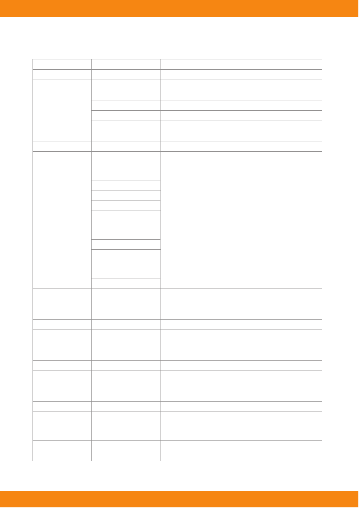
The LCD control panel display shows the menu items you select from the menu map on page #10. When a
menu function is selected, the display will show immediately the rst available option for the selected menu
function. To select a menu item, press <ENTER>.
To navigate through the LCD control panel, use the <UP/DOWN> buttons to scroll through the menu options. Press the <ENTER> button, then use the <UP/DOWN> buttons to view any sub-menu options. Press
<ESC> to continue without saving, or press <ENTER> button, then the <ESC> to save and return to the
previous menu item.
Function
Page 11
Manual | Storm1000
Menu Sub-menu
Address Set DMX Address
Auto Mode 1
Mode 2
Mode 3
Mode 4
Mode 5
Mode 6
Speed 000-031
Test LED All on
Red on
Green on
Blue on
White on
Red 1 on
Red 2 on
Green 1 on
Green 2 on
Blue 1 on
Blue 2 on
White 1 on
White 2 on
Fade on
Temp <ENTER>
Time <ENTER>
Cong DMX Status
001-512
Auto Mode 1
Auto Mode 2
Auto Mode 3
Auto Mode 4
Auto Mode 5
Auto Mode 6
Auto Run Speed
All On + Individual LED Segment
Testing
Internal Temperature
Total Run Time
Value Hold / Holds the last DMX values if signal is lost
Value Clear / Clears the DMX values if signal is lost
Display Mode
Temp Unit CS
Display Mode / LCD Display ON or Auto OFF
Channel 1 (1ch DMX mode)
Channel 3 (3ch DMX mode)
Channel 4 (4ch DMX mode)
Channel 7 (7ch DMX mode)
Channel 8 (8ch DMX mode)
Channel 16 (16ch DMX mode)
Pixel 4 (4ch DMX pixel control)
Pixel 8 (8ch DMX pixel control)
Key Lock / Menu buttons lock after 30sec of inactivity (push more than
once to temporarily unlock buttons).
Key Unlock / Menu buttons are not locked.
Load Default
Load Default Resets all values to default
Page 12

Manual | Storm1000
DMX Mode
Allows the unit to be controlled by any universal DMX controller.
Set the Starting DMX Address:
The default mode for the xture is DMX, so the rst menu item that you can edit is the starting DMX address.
1.) Press the <UP/DOWN> buttons until you reach Address.
2.) Push the <ENTER> button.
3.) Use the <UP/DOWN> buttons to select a channel from 001-512.
4.) Press the <ENTER> button to conrm.
5.) Press the <ESC> button to return to the main menu.
Select the DMX Channel Mode:
1.) Press the <UP/DOWN> buttons until you reach Cong.
2.) Push the <ENTER> button.
3.) Using the <UP/DOWN> buttons, highlight DMX Mode, then press <ENTER>.
4.) Use the <UP/DOWN> buttons to select 1, 3, 4, 7, 8, 16, or 4/8 pixel modes.
5.) Press <ENTER>, and then press the <ESC> button until you reach the Address screen.
Master/Slave Mode:
1.) Disconnect xture(s) from any DMX signal source.
2.) Set each xture to matching DMX modes.
3.) Connect all xtures together via DMX. The rst xture in the DMX chain will be the master, followed by the
slave xtures.
4.) Connect DMX controller to the master unit for DMX control.
Load Default Settings:
1.) Press the <UP/DOWN> buttons until you reach Load Default.
2.) Push the <ENTER> button.
Auto & Standalone Modes:
Allows a single or Master/Slaved units to run factory installed programs at user selectable speeds.
Auto Mode:
1.) Press the <UP/DOWN> buttons until you reach Auto.
2.) Push the <ENTER> button.
3.) Use the <UP/DOWN> buttons to select from Mode 1 to Mode 6.
4.) Press the <ENTER> button to conrm.
Auto Program Speed:
1.) Press the <UP/DOWN> buttons until you reach Speed.
2.) Push the <ENTER> button.
3.) Use the <UP/DOWN> buttons to select from 000-031.
4.) Press the <ENTER> button to conrm.
Page 13

Manual | Storm1000
Additional Features:
Never thought you would ever see so many nifty neato features in a strobe light did you?
Temperature:
IMPORTANT - Brightness will decrease when the LED temperature rises over 55ºC. If a temperature of +70ºC is
reached, the overheat protection sensor will activate, initiating blackout until a safe temperature is reached. It’s
highly recommended to not use the LEDs at full strobe brightness for longer than a 1 minute period. You can
safely use the xture as a normal wash in 4/8 pixel modes which are programmed to achieve a max of 40%
strobe brightness.
1.) Press the <UP/DOWN> buttons until you reach Temp.
2.) Push the <ENTER> button.
3.) The display will show the current temperature in Celsius degrees.
Signal Loss Settings: In the event of DMX signal loss, you can set the xture to either hold its last received
DMX signal values, or clear them.
1.) Press the <UP/DOWN> buttons until you reach Cong.
2.) Push the <ENTER> button.
3.) Using the <UP/DOWN> buttons, navigate to DMX Status, then press the <ENTER> button.
4.) Use the <UP/DOWN> buttons to select either Value Hold, or Value Clear.
5.) Press the <ENTER> button to conrm.
LCD Display On/Auto O: Display mode On will keep the LCD illuminated continually, Auto will shut the display o after 30 seconds of inactivity.
1.) Press the <UP/DOWN> buttons until you reach Cong.
2.) Push the <ENTER> button, and navigate to Display Mode.
3.) Push the <ENTER> button, then select either On or Auto, and press the <ENTER> button.
Key (Button) Protection Mode:
With Key Lock active, buttons will be unresponsive to any initial button press after 30 seconds of inactivity. Temporary unlock will occur with more than 1 button press. To disable this feature, activate Key Unlock.
1.) Press the <UP/DOWN> buttons until you reach Cong.
2.) Push the <ENTER> button.
3.) Press the <UP/DOWN> buttons until you reach Key Mode, then press<ENTER>.
4.) Use the <UP/DOWN> buttons to select either Key Lock, or Key Unlock, and press the <ENTER> button.
Temp Unit CS:
1.) Press the <UP/DOWN> buttons until you reach Cong.
2.) Push the <ENTER> button, and navigate to Temp Unit CS
3.) Using the <UP/DOWN> buttons to select Celsius degree or Fahrenheit degree
Page 14
Manual | Storm1000
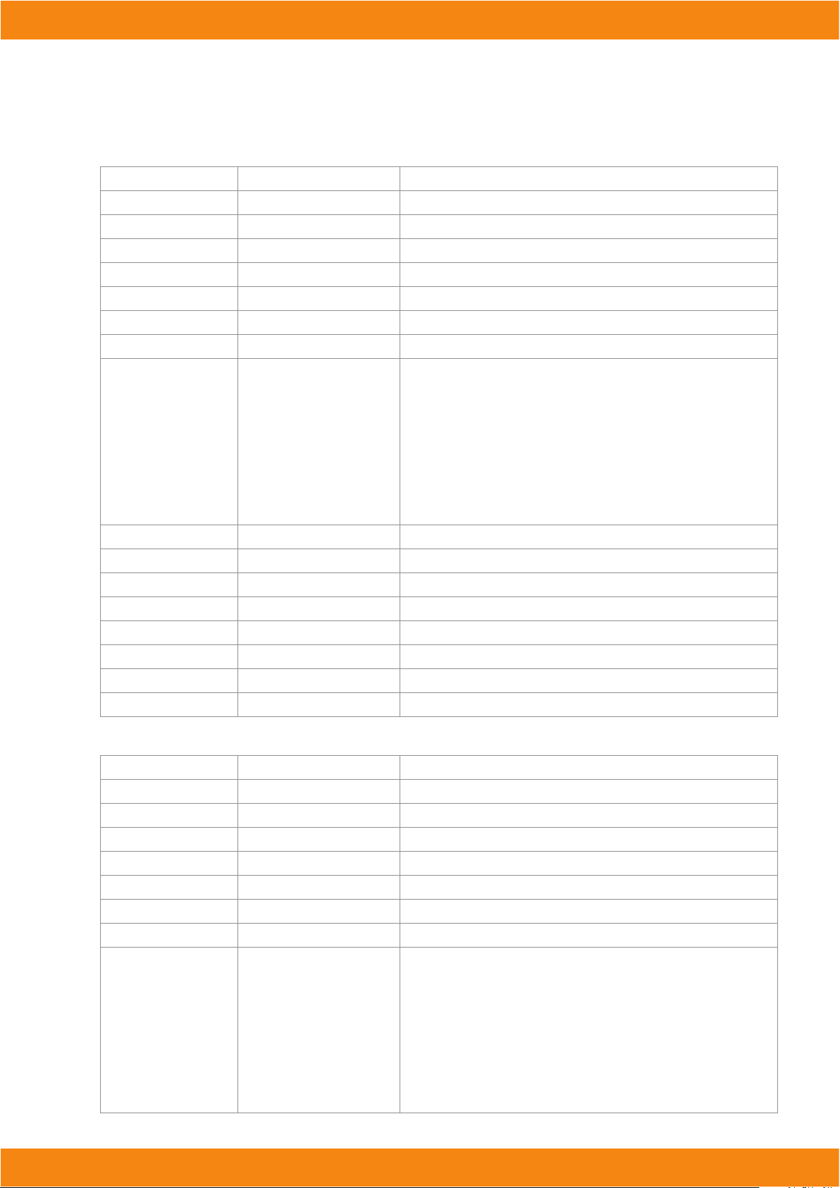
DMX Values In-Depth (16-Channel Mode)
Ch. Value Function
1
2 000 <--> 255
3 000 <--> 255
4 000 <--> 255
5 000 <--> 255
6 000 <--> 255
7 000 <--> 255
8
9 000 <--> 255
10 000 <--> 255
11 000 <--> 255
12 000 <--> 255
13 000 <--> 255
14 000 <--> 255
15 000 <--> 255
16 000 <--> 255
000 <--> 255
000 <--> 005
006 <--> 042
043 <--> 085
086 <--> 128
129 <--> 171
172 <--> 214
215 <--> 255
Master Dimmer (0-100%)
Red segment Intensity (0-100%)
Green segment Intensity (0-100%)
Blue segment Intensity (0-100%)
White segment Intensity(0-100%)
Flash duration (0-full on)
Strobe rate (0-30Hz)
Built-In Programs
No function
Ramp up eect (slow <--> fast)
Ramp down eect (slow <--> fast)
Ramp up-down eect (slow <--> fast)
Random eect (slow <--> fast)
Lightning eect (slow <--> fast)
Spike eect
Red1/Segment 1 Intensity (0-100%)
Green1/Segment 2 Intensity (0-100%)
Blue1/Segment 3 Intensity (0-100%)
White1/Segment 4 Intensity (0-100%)
Red2/Segment 5 Intensity (0-100%)
Green2/Segment 6 Intensity (0-100%)
Blue2/Segment 7 Intensity (0-100%)
White2/Segment 8 Intensity (0-100%)
DMX Values In-Depth (8-Channel Mode)
Menu Sub-menu
1
2 000 <--> 255
3 000 <--> 255
4 000 <--> 255
5 000 <--> 255
6 000 <--> 255
7 000 <--> 255
8
000 <--> 255
000 <--> 005
006 <--> 042
043 <--> 085
086 <--> 128
129 <--> 171
172 <--> 214
215 <--> 255
Function
Master Dimmer (0-100%)
Red segment Intensity (0-100%)
Green segment Intensity (0-100%)
Blue segment Intensity (0-100%)
White segment Intensity(0-100%)
Flash duration (0-full on)
Strobe rate (0-30Hz)
Built-In Programs
No function
Ramp up eect (slow <--> fast)
Ramp down eect (slow <--> fast)
Ramp up-down eect (slow <--> fast)
Random eect (slow <--> fast)
Lightning eect (slow <--> fast)
Spike eect
Page 15
Manual | Storm1000
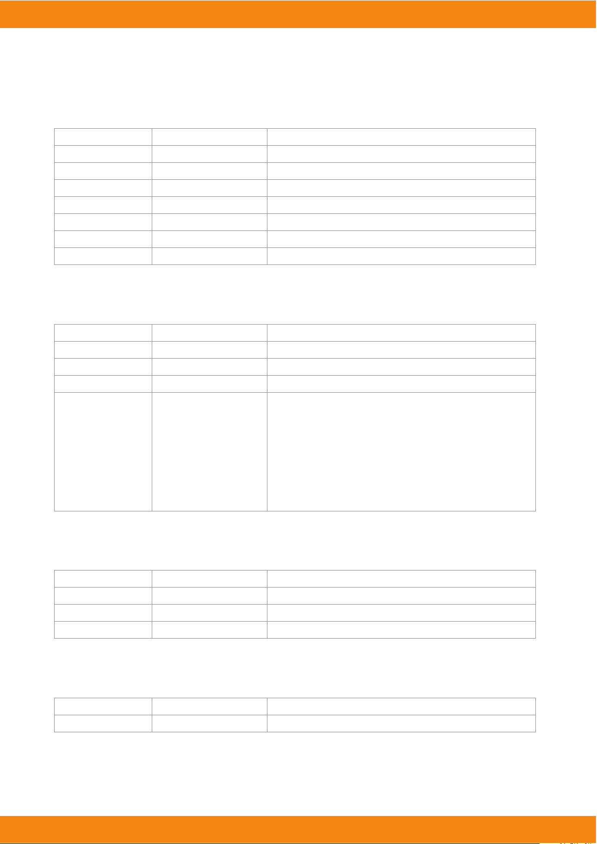
DMX Values In-Depth (7-Channel Mode)
Menu Sub-menu
1
2 000 <--> 255
3 000 <--> 255
4 000 <--> 255
5 000 <--> 255
6 000 <--> 255
7 000 <--> 255
000 <--> 255
Function
Master Dimmer (0-100%)
Red segment Intensity (0-100%)
Green segment Intensity (0-100%)
Blue segment Intensity (0-100%)
White segment Intensity(0-100%)
Flash duration (0-full on)
Strobe rate (0-30Hz)
DMX Values In-Depth (4-Channel Mode)
Menu Sub-menu
1
2 000 <--> 255
3 000 <--> 255
4
000 <--> 255
000 <--> 005
006 <--> 042
043 <--> 085
086 <--> 128
129 <--> 171
172 <--> 214
215 <--> 255
Function
Dimmer (0% <--> 100%)
Flash Duration (0% <--> 100%)
Strobe Rate (0-30Hz)
Built-In Programs
No function
Ramp up eect (slow <--> fast)
Ramp down eect (slow <--> fast)
Ramp up-down eect (slow <--> fast)
Random eect (slow <--> fast)
Lightning eect (slow <--> fast)
Spike eect
DMX Values In-Depth (3-Channel Mode)
Menu Sub-menu
1
2 000 <--> 255
3 000 <--> 255
000 <--> 255
Function
Dimmer (0% <--> 100%)
Flash Duration (0% <--> 100%)
Strobe Rate (0-30Hz)
DMX Values In-Depth (1-Channel Mode)
Menu Sub-menu
1
000 <--> 255
Function
Dimmer (0% <--> 100%)
Page 16
Manual | Storm1000
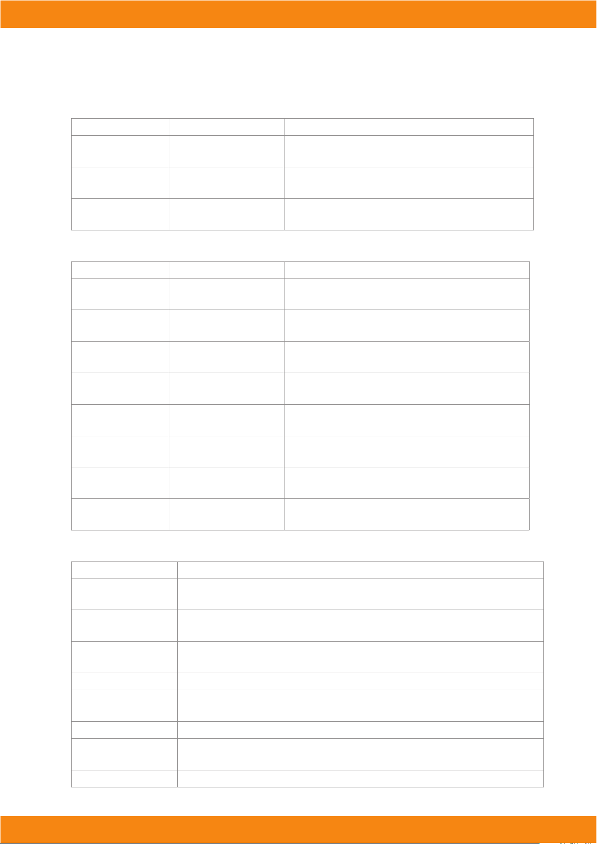
DMX Values In-Depth (4-Channel Pixel Mode)
Menu Sub-menu
1 000 <--> 021
022 <--> 255
2
3
000 <--> 021
022 <--> 255
000 <--> 021
022 <--> 255
Function
No Function
Red/Segment Intensity (0% <--> 100%)
No Function
Green/Segment Intensity (0% <--> 100%)
No Function
Blue/Segment Intensity (0% <--> 100%)
DMX Values In-Depth (8-Channel Pixel Mode)
Menu Sub-menu
1 000 <--> 021
022 <--> 255
2
3
4
5
6
7
8
000 <--> 021
022 <--> 255
000 <--> 021
022 <--> 255
000 <--> 021
022 <--> 255
000 <--> 021
022 <--> 255
000 <--> 021
022 <--> 255
000 <--> 021
022 <--> 255
000 <--> 021
022 <--> 255
Function
No Function
Red/Segment 1 Intensity (0% <--> 100%)
No Function
Green/Segment 1 Intensity (0% <--> 100%)
No Function
Blue/Segment 1 Intensity (0% <--> 100%)
No Function
White/Segment 1 Intensity (0% <--> 100%)
No Function
Red/Segment 2 Intensity (0% <--> 100%)
No Function
Green/Segment 2 Intensity (0% <--> 100%)
No Function
Blue/Segment 2 Intensity (0% <--> 100%)
No Function
White/Segment 2 Intensity (0% <--> 100%)
Troubleshooting
Symptom Solution
Fixture Auto- Shut O If it is stopped or dimmer than normal, the unit may have shut itself o due to high heat. This is to
protect the xture from overheating. No Light Output Check to ensure xture is operating under
No Light Output Check to ensure xture is operating under correct mode, IE sound active/auto/DMX/Etc., if appli-
cable.
Chase Speed
Too Fast/Slow
No Power Check fuse, AC cord and circuit for malfunction.
Blown Fuse Check AC cord and circuit for damage, verify that moving parts are not restricted and that unit’s
Slow Movement Check that speed channels are set appropriately.
Fixture Not Responding /
Responding Erratically
Fixture Moving On Its Own
Check to ensure proper setup of speed adjustment.
ventilation is not obstructed
Make sure all connectors are seated properly and securely. Use Only DMX Cables and/or check
cables for defects Install a Terminator. Reset xture(s).
Verify proper mode of operation. Is the xture in “Auto” mode?
Page 17
Manual | Storm1000
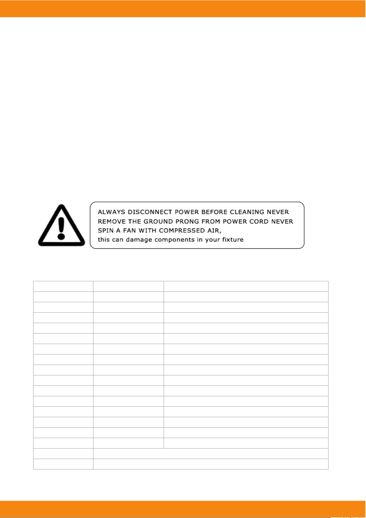
5. APPENDIX
Your xture will require regular cleaning to prevent a build up of dust and smoke debris on the optics and
housing. After disconnection of power, wipe down the xture with a damp cloth. Never use alcohol or solvents
as this may damage the nish. Use glass cleaner for glass surfaces such as external lens or mirrors. A dry paint
brush is an excellent tool to remove surface dust.
Be sure to periodically check for loose parts that could damage the xture or potentially allow the xture to cause injury. Make sure all overhead and wall installations have a secondary safety device installed such as a safety
cable rated for your xture type and size. Check the power cord as well, make sure there is no damage that could
cause electrical shock, never remove the ground prong.
There are no user-servicable parts in this xture. Do not attempt to open and repair this xture. Return to the
factory for repair
Tech Specs
Power
Light Source
Optical
Thermal
Control
Other Information
Warranty
Operating Voltage 220-240VAC 50/60Hz
Power Consumption 800W Max, 5A, pf: .75
LED 630RGB LEDs,630 white leds, 50,000 hrs.
Beam Angle 140 degree
Luminous 38,000 lm
Max.Operating Temp.
Protocol
DMX Channels
Input
Output
Operating Modes
A lot of things look cooler in slow motion. Eating isn’t one of them.
1-year limited warranty, does not cover malfunction caused by damage to LED’s.t
104 degrees F (40 degrees C) ambient
USITT DMX-512
1/3/4/7/8/16 Channels
3/5-pin XLR Male
3/5-pin XLR Female
Standalone, Master/Slave, Auto Mode
Page 18

Manual | Storm1000
Das Lichttechnikhaus Vertriebs GmbH
Rudolf-Diesel-Str. 3, D-89312 Günzburg
Telefon +49 (0) 82 21 207 98-0
 Loading...