

Page 1
User Manual: Squareled Edgy Akku & Wireless 4x25W RGBAW
Page 2
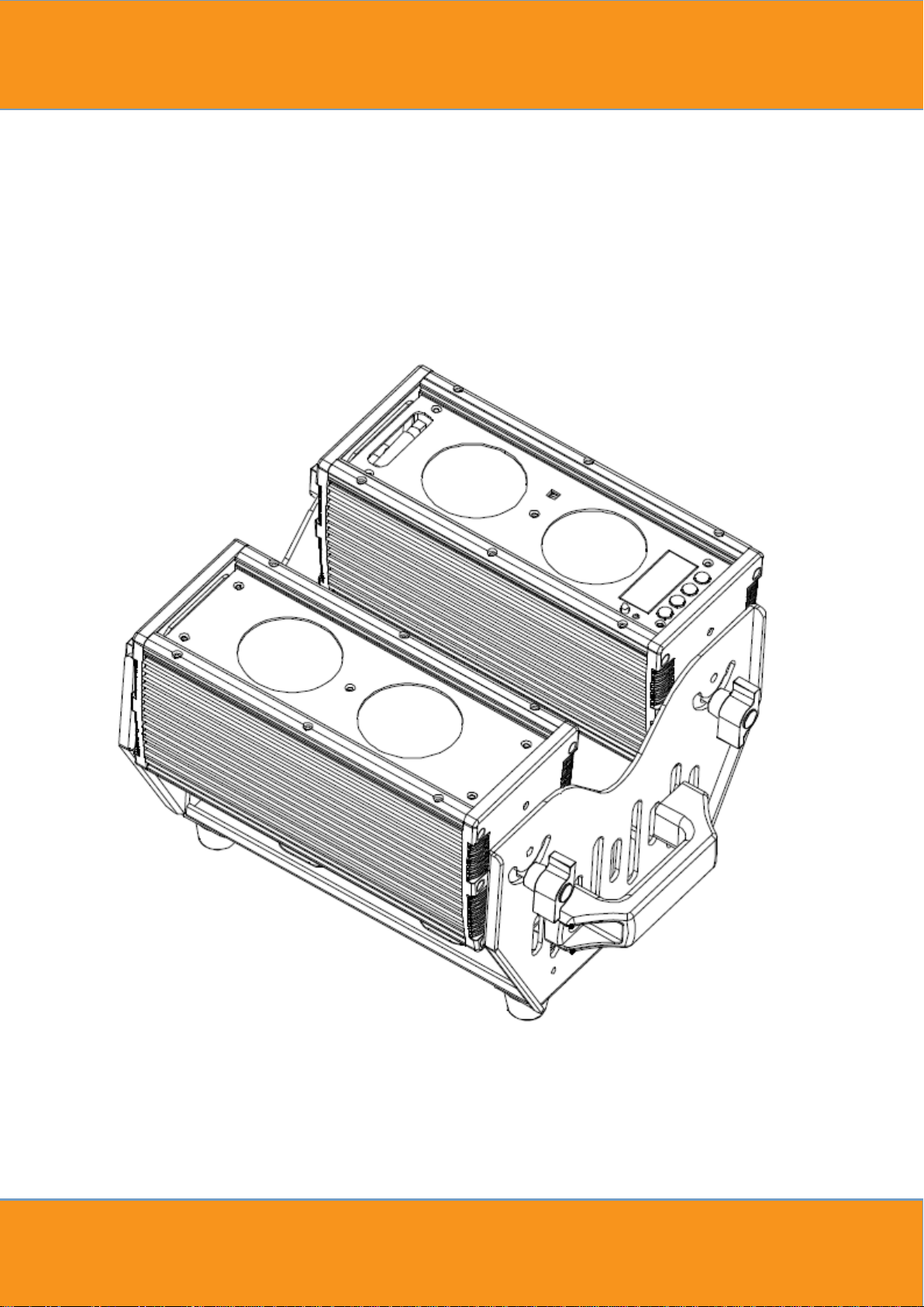
SquareLED
Edgy Akku + Wireless 4x25W RGBAW 5in1
USER MANUAL
Page 3
Please read over this manual before operating the light
Catalogue
1. Summary ................................................................................................................ 1
2. Safety Instruction ................................................................................................... 2
3. Outside Size Picture ............................................................................................... 3
4. Main Function ........................................................................................................ 4
5. DMX Control Function ............................................................................................ 5
6. Display Operation instruction ................................................................................ 8
7. Instruction for compatible Sweden DMX wireless module ................................... 14
8. Ifrared keyboard operation .................................................................................. 15
9. Operating Control Instruction .............................................................................. 16
10. XLR cable connecting ........................................................................................... 16
11. Trouble Shooting .................................................................................................. 17
Page 4

1
1. Summary
Summary
Thank you for purchasing our SquareLED EDGY. Please read these instructions carefully before begin
and operate the fixtures according to these instructions to avoid any possible damages and
causes by misusage
accidents
Product introduction
The SquareLED EDGY light uses casting aluminum housing
hydrodynamic form. Appearance shows. It adopts high power
made of R,G,B,A,W 5-IN-1 LED, And long life span, low consumption, good
high brightness are the most prominent features. Each kind of LED can be independently dimmed. The
built-in program includes dimming, strobe, eotic, gradual change, fading and so on.
performs low weight and consumption, stable
signal is requested.
capability and long life. International standard DMX 512
5-in-1
, designed in a fashion of
LED, which refers to single LED is
color mixing effect and
It uses power switch,
Packing List
LF2504 1 PC
DMX Signal Cable 1 Set
Power cable 1 PC
User Manual
Warranty Card
Page 5

2
2. Safety Instruction
Safety Notes
! Enquire the skilled people before any repair;
! Always make sure disconnect from the power source before setting up, serving and moving;.
! Avoid direct eye exposure to the fixture when it is on;
Safety instruction
● Make sure the power supply voltage are consistent with this lights,Ensure the use of voltage is in the range
of the request technical parameter.
●Before the installation, please check the light’s fasteners and mechanical structure have been received in
good condition and appear no damage.
●
This light is designed for indoor use;
●The fixtures maybe mounted in any position provided there is adequate room for ventilation. Make sure
there are no inflammable and explosive items (ornaments) in 0.5 meters away.
●Yellow / green cabling earthling safety; no flicker when the fixture is working on.
working
temperature is lower than 40 degree.
Page 6
3
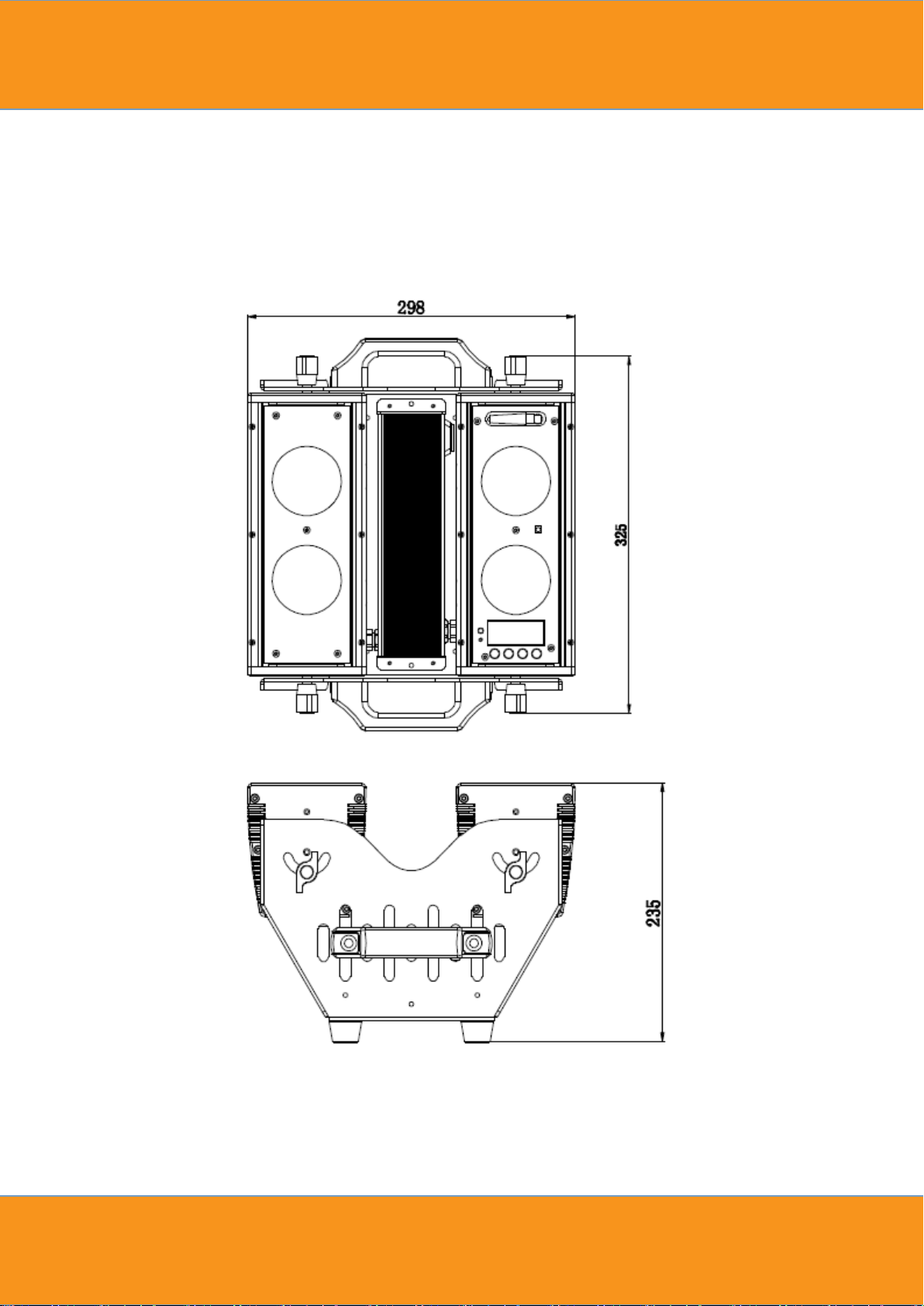
3. Outside Size Picture
Page 7

4
4. Main Function
Input voltage: AC 100V-264V/47-63HZ
Power consumption:120W
Lamp Type:25W LED 5-in-1 R、G、B、A、W (4PCS)
Life span: 50000~100000hours
PWM Dimmer:1500HZ(16666 grades)
Control Signal:DMX512
Control mode:stand alone/ Master/Slaver
Ifrared keyboard control
2.4G wireless DMX512
Channel:16CH/11CH/10CH/11CH./6CH/5CH
Function Effect: dimmer, strobe, gradual change
Battery charge time:5.5 hours
Full power battery duration:5.5 hours
Cooling mode: Natural Convection
Anti-electricity intension:1.5KV
Insulation Resistance:>2MΩ
Beam Angle: 15°,25°,45°,60° Optional
Net weight: 9.52Kg
Page 8
5
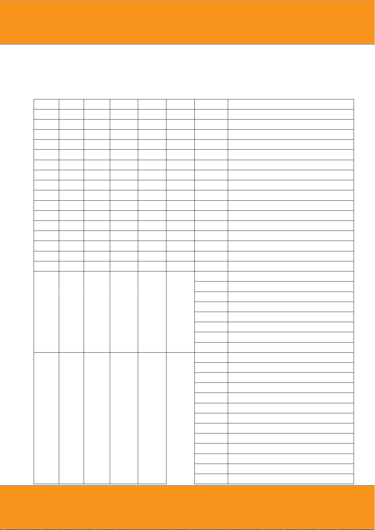
5. DMX Control Function
5CH
6CH
11CH.
10CH
11CH
16CH
Value
Function
-
CH1
CH1 - CH1
CH1
0-255
Dim all
CH1
CH2
CH2 - - - 0-255
R
CH2
CH3
CH3 - - - 0-255
G
CH3
CH4
CH4 - - - 0-255
B
CH4
CH5
CH5 - - - 0-255
A
CH5
CH6
CH6 - - - 0-255
W
- - -
CH1
CH2
CH2
0-255
R1
- - -
CH2
CH3
CH3
0-255
G1 - - - CH3
CH4
CH4
0-255
B1 - - - CH4
CH5
CH5
0-255
A1 - - - CH5
CH6
CH6
0-255
W1 - - - CH6
CH7
CH7
0-255
R2 - - - CH7
CH8
CH8
0-255
G2 - - - CH8
CH9
CH9
0-255
B2 - - - CH9
CH10
CH10
0-255
A2 - - - CH10
CH11
CH11
0-255
W2
- - CH7 - -
CH12
0-5
No strobe
6-20
Not synchronous strobe(slow to fast)
21-60
Synchronous strobe(slow to fast)
61-100
Electronic Sinewave(slow to fast)
101-140
Random Strobe(slow to fast)
141-180
Opening pulse(slow to fast)
181-220
Closing pulse(slow to fast)
221-255
Electronic Squarewave(slow to fast)
-
-
CH8(C
H8
Prior to
CH10)
-
-
CH13
(CH13
Prior to
CH15)
0-5
No effect
6-10
CT01(Call custom color in menu settint)
11-15
CT02
16-20
CT03
21-25
CT04
26-30
CT05
31-35
CT06
36-40
CT07
41-45
CT08
46-50
CT09
51-55
CT10
56-60
AUTO 1
61-65
AUTO 2
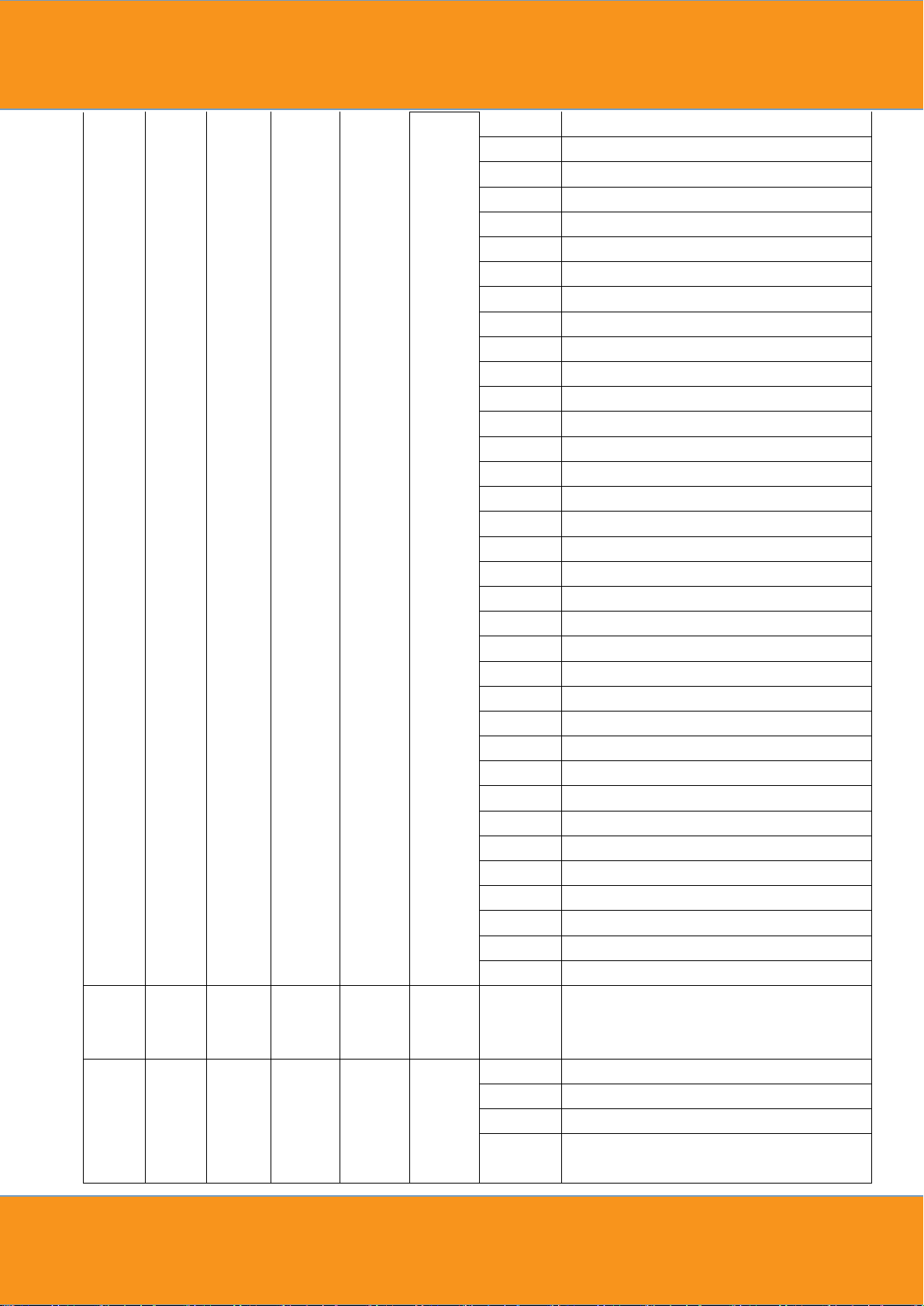
DMX Channels
Page 9
6
66-70
AUTO 3
71-75
AUTO 4
76-80
AUTO 5
81-85
AUTO 6
86-90
AUTO 7
91-95
AUTO 8
96-100
AUTO 9
101-105
AUTO 10
106-110
AUTO 11
111-115
AUTO 12
116-120
AUTO 13
121-125
AUTO 14
126-130
AUTO 15
131-135
AUTO 16
136-140
AUTO 17
141-145
AUTO 18
146-150
AUTO 19
151-155
AUTO 20
156-160
AUTO 21
161-165
AUTO 22
166-170
AUTO 23
171-175
AUTO 24
176-180
AUTO 25
181-185
AUTO 26
186-190
AUTO 27
191-195
AUTO 28
196-200
AUTO 29
201-205
AUTO 30
206-210
AUTO 31
211-215
AUTO 32
216-220
AUTO 33
221-225
CHASE1
226-230
CHASE2
231-235
CHASE3
236-255
Reserved
- - CH9 - -
CH14
0-255
Auto
speed,fast->slow,(AT01-AT05:0-255S,AT06AT33:0-25.5S)
- - CH10 - -
CH15(R
GB
color
mixing
instead
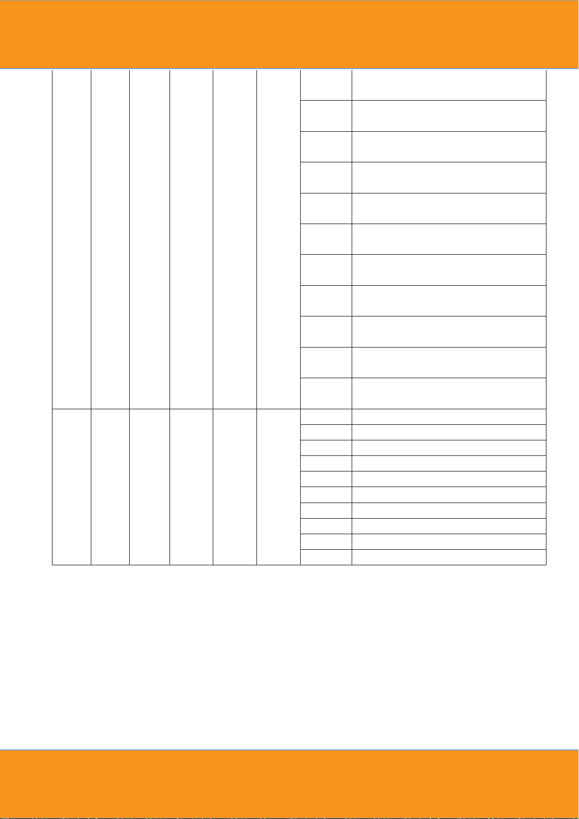
Virtual colour wheel
0-10
No effect
11
Blue (Blue=full, Red+Green+White=0)(step)
12-50
Red=0, Green->up,Blue =full,
White=0(proportional)
Page 10
7
of RGB
channel
)
51
Light Blue (Red=0, Green=full, Blue =full,
White=0)(step)
52-90
Red=0, Green=full, Blue->down,
White=0(proportional)
91
Green (Red=0, Green=full, Blue =0,
White=0)(step)
92-130
Red->up, Green=full, Blue=0,
White=0(proportional)
131
Yellow (Red=full, Green=full, Blue=0,
White=0)(step)
132-170
Red=full, Green->down, Blue=0,
White=0(proportional)
171
Red(Red=full, Green=0, Blue=0,
White=0)(step)
172-210
Red=full, Green=0, Blue->up,
White=0(proportional)
211
Magenta (Red=full, Green=0, Blue=full,
White=0)(step)
212-250
Red -> down, Green=0, Blue=full,
White=0(proportional)
251-255
Blue (Red=0, Green=0, Blue=full,
White=0)(step)
- - CH11 - -
CH16
0-10
Use the dimmer mode which menu had set up
11-20
Linear curve
21-30
Square law curve
31-40
Inverse square law curve
41-50
S-curve
51-60
Linear curve and smooth
61-70
Square law curve and smooth
71-80
Inverse square law curve and smooth
81-90
S-curve and smooth
91-255
Use the dimmer mode which menu had set up
Page 11
8
TAB
LEVEL 1
LEVEL 2
LEVLE 3
LEVEL 4
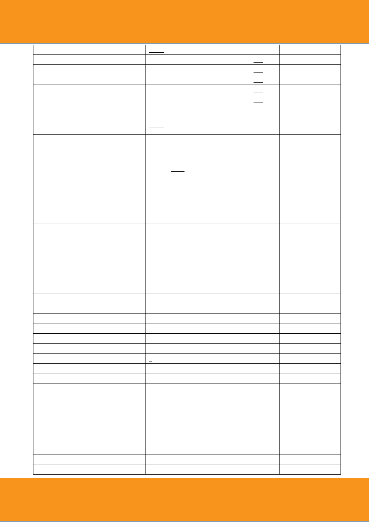
ADDR(Address)
001-512
STAT(Static
control)
R1
0-255 *
G1
0-255 *
B1
0-255 *
A1
0-255 *
W1
0-255 *
R2
0-255 *
G2
0-255 *
B2
0-255 *
A2
0-255 *
W2
0-255 *
SHUT
0-255 *
SET(Set)
SIGN(DMX signal
selection)
2.4G(wirelsee)/CABL(Cable)
WIRE(Wireless set)
REST(reset)
YES/NO
KEY
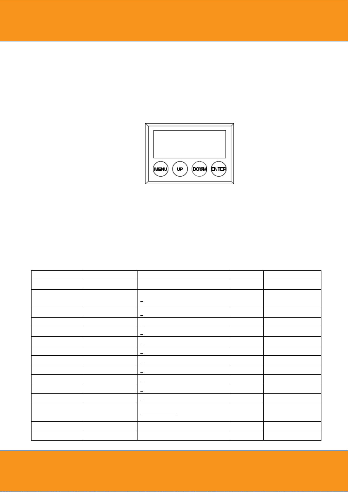
6. Display Operation instruction
MENU : access the menu or return to a previous menu option
ENTER: select the current menu option
UP: menu selection or parameter increments
DOWN: menu selection or parameters decrease
Menu Tree
Page 12
9
BAT(battery output)
HIGH/MIDDLE/LOW
CAL(Calibration)
R
0-255
G 0-255
B 0-255
A 0-255
W
0-255
USE
YES/NO
CHMD(Channel
mode)
16CH/11CH/10CH/11CH./6CH/5CH
DIM(Dimming
mode)
LIN(linear)/SQR(square
law)/ISQR(inverse square
law)/SCUR(S-curve)/LIN.(linear
smooth)/SQR.(square law
smooth)/ISQR.(inverse square law
smooth)/SCUR.(S-curve smooth)
DISY(Display set)
ON(Permanent on)
2 OFF (2 minutes off)
SHOW
ADDR/BAT
LOCK
YES/NO
CTST(Custom
color set)
CT01
R
0-255
. G
0-255
. B
0-255
. A
0-255
W 0-255
CT10
AUTO(Auto)
AT01
RUN.. *
.
RUN.. *
.
RUN.. *
.
RUN.. *
AT33
RUN.. *
ATSP(Auto speed)
0-255(S)
CHS1(Chase 1)
RUN.. *
CHS2(Chase 2)
RUN.. *
CHS3(Chase 3)
RUN.. *
PROG(Program)
CHS1(Chase 1)
SC01(Scene 1)
R1
0-255
. .
G1
0-255
. .
B1
0-255
. .
A1
0-255
. .
W1
0-255
. .
R2
0-255
. .
G2
0-255
. .
B2
0-255
Page 13

10
. .
A2
0-255
. .
W2
0-255
. .
SHUT
0-255
. .
AUTO
NONE,AT01-AT33
. .
ATSP
0-255(S)
. .
TIME
0-255(S)
. .
WAIT
0-25.5(S)
. .
USE
YES/NO
. SC25(Scene 25)
CHS3(Chase 3)
INFO
(Information)
SOFT(Software
version)
Vx.x
BATTERY
0%-100%
POW(Power
reduction)
xxx%
TEM1
xxxC
TEM2
xxxC
LOAD(Load)
ST L(Setting load)
YES/NO
PR L(Program load)
YES/NO
SEND(Send)
YES/NO
Instructions:
When enter to the “*” position displayed on the LED, the light will automatically set as master and send
data to external. Other fixtures can receive this data and will synchronously running without manually set as
slave. When power cycle it will jump to the “*” position and running again. And in these position it will not
return back to the default display after two minutes.
6.1 DMX ADDRESS SETTING
1) Press the 【ENTER】 button in 【ADDR】 menu, then enter to the DMX address setting.
2) Press the【UP/DOWN】button to select【1-512】numerical value.
3) Press the【ENTER】button to escape and save.
6.2 STATIC SETTING
1) Press the【ENTER】button in 【STAT】menu, then enter to the static setting.
2) Press the【UP/DOWN】button to select 【RED1】【GREEN1】【BLUE1】...【WHITE2】and【SHUT】.
3) Press the【UP/DOWN】button to set up the【0-255】numerical value.
4) Press the【ENTER】button to escape and save.
Page 14

11
6.3 DMX signal selection setting
1) Press the【ENTER】button in【SIGN】menu, then enter to the DMX signal selection setting.
2) Press the【UP/DOWN】button to select【2.4G】,【CABLE】
3) Press the【ENTER】button to escape and save.
6.4 Wireless set
1) Press the【ENTER】button in【WIRE】menu, then enter to the wireless set.
2)【RESET】Analog the wireless module,it is the process of off and pressing the button then power
3)【KEY】similar as the external key.
6.5 Battery output setting
1) Press the【ENTER】button in【BAT】menu, then enter to the Battery output setting.
2) Press the【UP/DOWN】button to select【HIGH】,【MIDDLE】, 【LOW】
3) Press the【ENTER】button to escape and save.
6.6 COLOR CAST CALIBRATION SETTING
1) Press the【ENTER】button in 【CAL】menu, then enter to the color cast calibration setting.
2) Press the【UP/DOWN】button to select 【RED】,【GREEN】...【WHITE】
3) Press the【UP/DOWN】button to set up the【0-255】numerical value.
4) On the【USE】interface, pressing【YES】button means valid,【NO】means invalid.
5) Press the【ENTER】button to escape and save.
Illustrations: When pressing the【YES】button which means valid on the【USE】interface, the actual output value
of RED...WHITE is output in accordance with the percentage which the color cast calibration value divides 255.
6.7 CHANNEL MODE SETTING
1) Press the【ENTER】button in 【CHMD】menu, then enter to the channel mode setting.
2) Press the【UP/DOWN】button to select【16CH】,【11CH】【10CH】【11CH.】【6CH】【5CH】
3) Press the【ENTER】button to escape and save.
6.8 DIMMING MODE SETTING
1) Press the【ENTER】button in【DIM】menu, then enter to the dimming mode setting.
2) Press the【UP/DOWN】button to select【LIN】,【SQR】,【ISQR】,【SCUR】,【LIN.】,【SQR.
】,【ISQR.】and【SCUR.】.
Page 15
12
3) Press the【ENTER】button to escape and save.
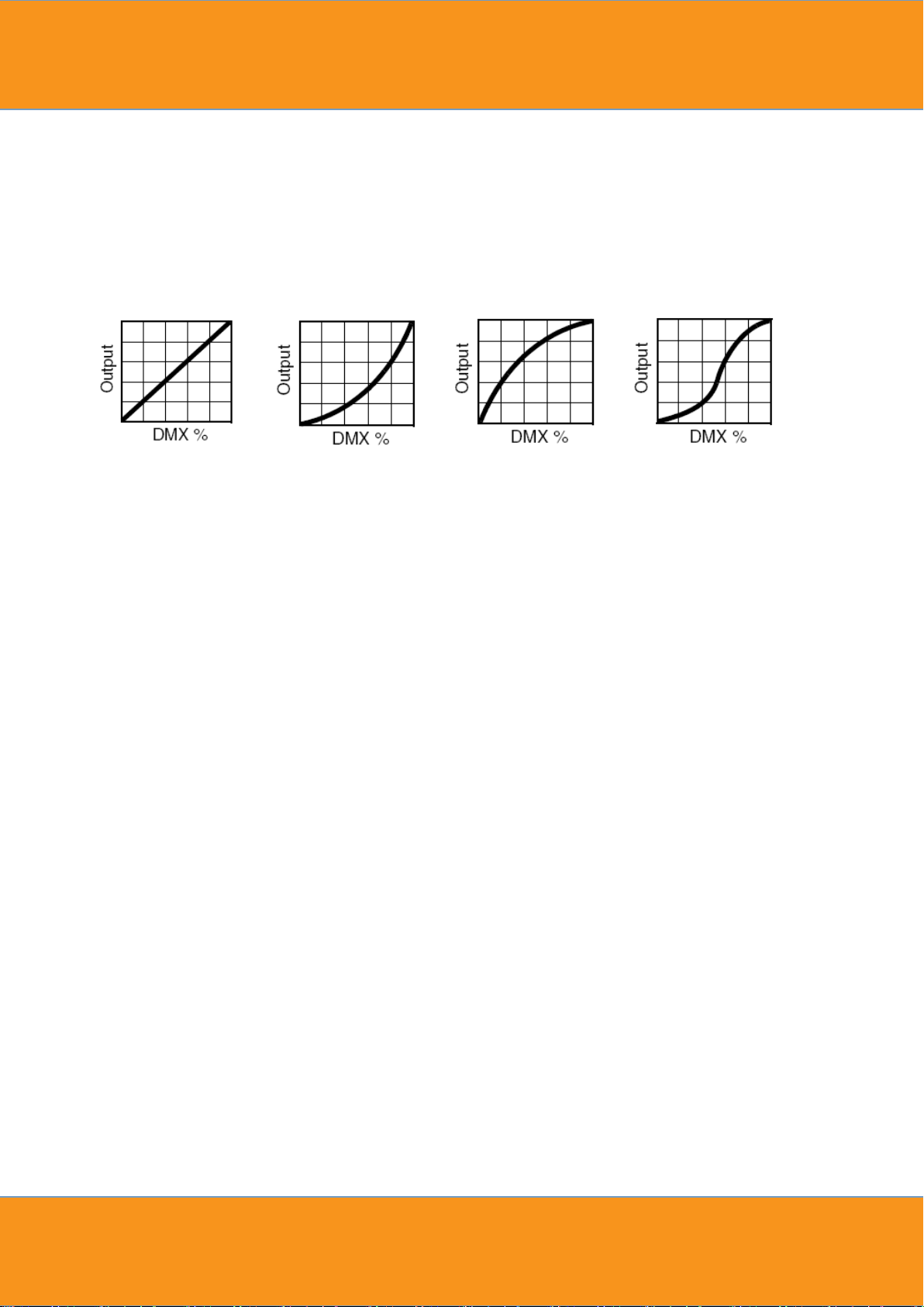
Illustrations:When setting【LIN.】,【SQR.】,【ISQR.】and 【SCUR.】 in 【DIM】 menu, there will be
added a little delay dimming effect for smooth..
Dimming curve:
Linear curve: square law curve: Inverse Square law curve: S-curve:
6.9 DISPLAY SETTING
1) Press the【ENTER】button in【DISY】menu, then enter to the display setting.
2) Press the【UP/DOWN】button to select【ON】,【2 MINITES OFF】
3) Press the【ENTER】button to escape and save.
6.10 TWO MINUTES TIME OUT DISPLAY SETTING
1) Press the【ENTER】button in【SHOW】menu, then enter to the two minutes time out display setting.
2) Press the【UP/DOWN】button to select【ADDR】,【BAT】
3) Press the【ENTER】button to escape and save.
6.11 AUTO LOCK KEY SETTING
1)pressing the MENU-UP-DOWN-ENTER-MENU-UP-DOWM-ENTER-MENU-UP-DOWN-ENTER.That means,
the unlock method is to press the MENU-UP-DOWN-ENTER three times cyclically,and the time between press
two keys can not over 3S,or start anew.
2) The methods are using need to meet certain key sequences and time limit, so that the rate of accidental
unlocking almost zero.
6.12 CUSTOM COLOR SETTING
1) Press the 【ENTER】 button in 【CTST】 menu, then enter to the custom color setting.
2) Press the 【UP/DOWN】 select 【CT01】…【CT10】
2) Press the【UP/DOWN】button to select【1-255】numerical value.
3) Press the【ENTER】button to escape and save.
6.13 AUTO RUN, SELF-PROGRAM RUN
Page 16
13
1)Press the【ENTER】button in【AUTO】menu, then enter to the auto run,self-program run.
2)Press the【UP/DOWN】button to select【AT01】…【AT05】,【AUTO SPEED】,【CHASE01】…【CHASE03
】
3)Press the【ENTER】button to start running.
6.14 EDIT SELF-PROGRAM
1) Press the【ENTER】button in【PROG】menu, then enter to the edit self-program.
2) Press the【UP/DOWN】button to select【CHASE01】…【CHASE03】
3) Press the【ENTER】button for confirmation and enter to the next menu.
4) Press the【UP/DOWN】button to select【SCENE01】…【SCENE20】
5) Press the【ENTER】button for confirmation and enter to the next menu.
6) Then press the【UP/DOWN】button to select【RED】…【SHUT】,【TIME】,【WAIT】,【USE】
7) Press the【UP/DOWN】button to set up the parameter which are needed.
8) Press the【ENTER】button t o escape and save.
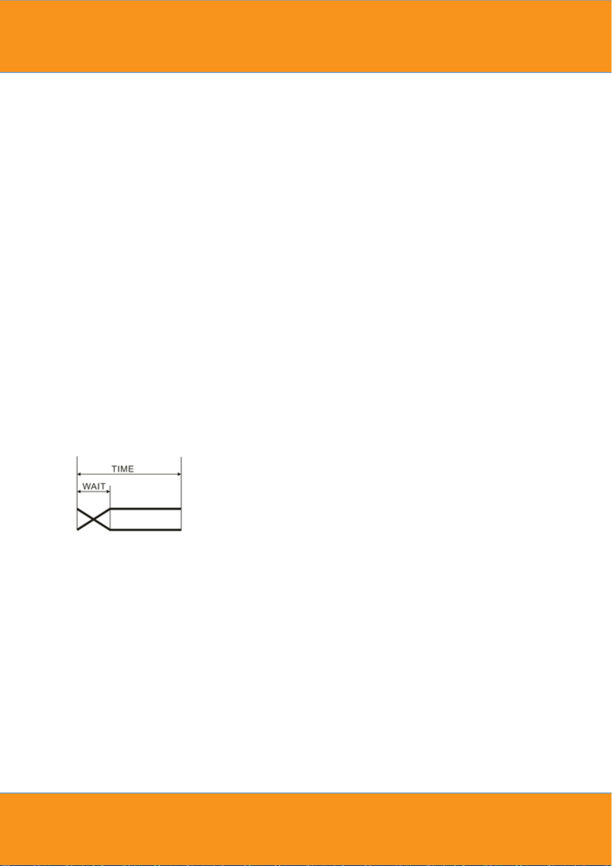
Illustrations:When【USE】 is set to be【NO】, or the parameter of【TIME】 is 0, it will not run this scene.When
【WAIT】is set to be FADE time, the running process isas the following chart showing.
6.15 CHECK THE LIGHTING INFORMATION
1) Press the【ENTER】button in【INFO】menu, then enter to the checking the lighting information.
2) 【SOFT】button is for software version information.
3) 【BAT】is battery level from 0% to 100%。
4) 【POW】button is for the current information of power reduction..
5) 【TEMP】Current temperature of lamp board.
6.16 LIGHTING SETTING PARAMETER RESET
1) Press the【ENTER】button in【ST L】menu, then enter to the lighting setting parameter reset.
2) Press the【UP/DOWN】button to select【YES】.
Page 17

14
3) Press the【ENTER】button to escape and save.
Illustrations: “ADDR” “CTST” and “PROG” are not reset, the others reset to the underlined value of the word.
6.17 【PROG】SELF-PROGRAMMING PARAMETER RESET
1) Press the【ENTER】button in【PR L】menu, then enter to the【PROG】self-programming parameter reset.
2) Press the【UP/DOWN】button to select【YES】.
3) Press the【ENTER】button to escape and save.
6.18 LIGHTING PARAMETER DOWNLOADING EACH OTHER VIA DMX
CABLE
1) Press the【ENTER】button in【SEND】menu, then enter to sending parameter to other lightings.
2) Press the【UP/DOWN】button to select【YES】.
3) Press the【ENTER】button to confirm sending.
Illustrations:
1)Please disconnect the connection of projector and DMX console before sending the parameter.
2)The information of【ADDR】、【CAL】can’t be sent, can’t be downloaded each other.
3)There will be an automatic reset of the other projectors after receiving parameter correctly.
7. Instruction for compatible Sweden DMX wireless
module
1) There are 4 modes: compatible Sweden receive mode(green indicator), compatible Sweden transmit
mode(blue indicator), normal mode(yellow indicator),custom mode(red indicator)
2) After 【RESET】, and then press【KEY】to switch above modes, select needed mode and press【KEY】 one
second to confirm and save it.
3) Under compatible Sweden DMX receive mode, press 【KEY】 3 seconds to delete matching between light and
transmitter.
4) Under compatible Sweden DMX transmit mode, press 【KEY】to match receive mode, press 3 seconds will
delete matched mode.
5) Working in normal mode, indicator has 7 colors for option, when light and transmitter indicator are in the
Page 18
15
same color, can receive and transmit data.
6) User-defined function is not available.
7) Notice: compatible Sweden DMX mode in this lights has complete data for sending and receiving, but
transmit function is not available here.
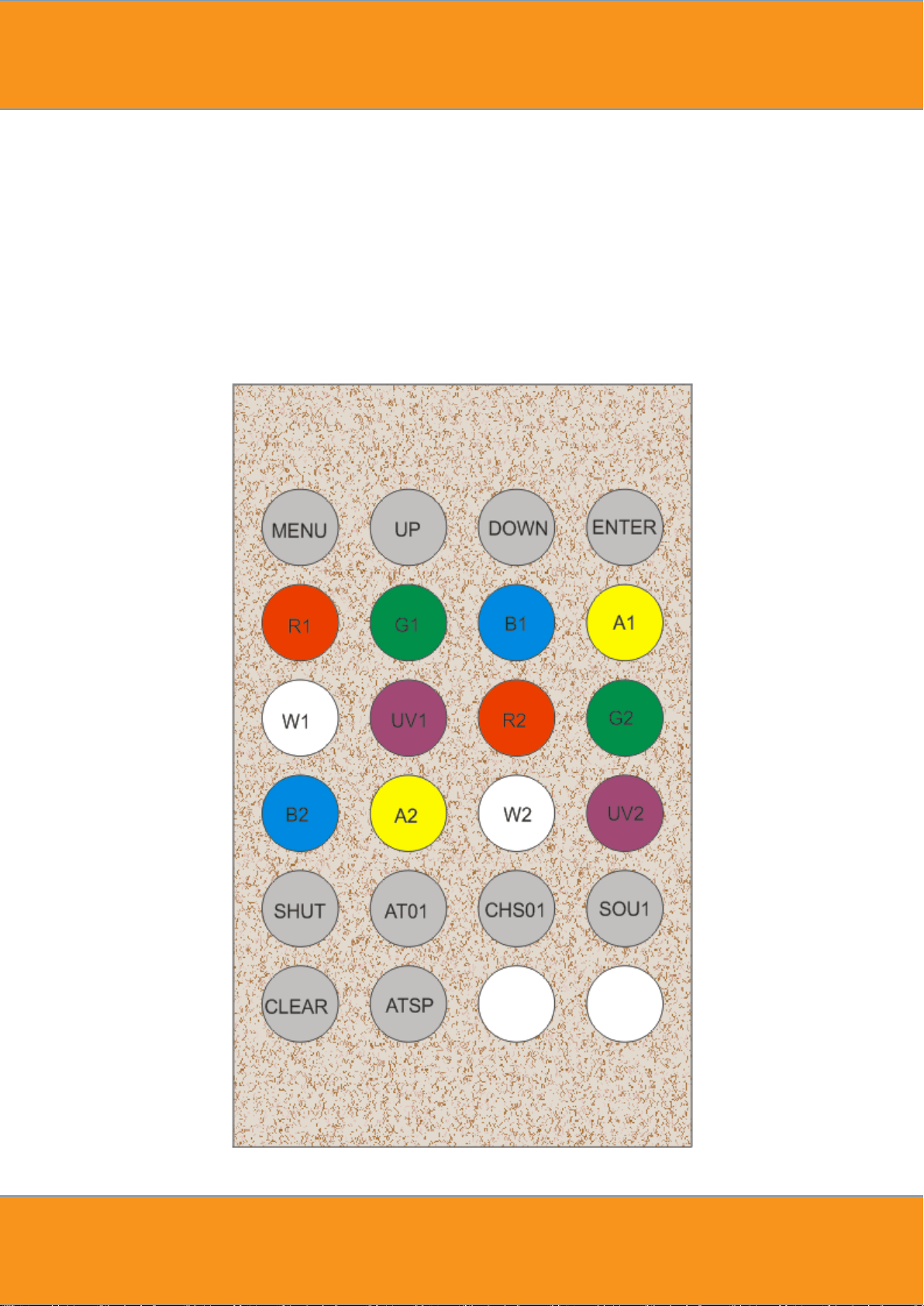
8. Infrared keyboard operation
Page 19
16
1) 【MENU】, 【UP】, 【DOWN】, 【ENTER】is same as the keys on the fixture.
2) 【R1】...【W2】,【SHUT】is shortcut for 【STAT】.
3) 【AT01】,【CHS01】, 【ATSP】,【SOU1】is correspond to the positon of 【AT01】,【CHS01】,【SOU1
】 in the MENU.
4) 【CLEAR】is clear the value of 【R1】, 【G1】... 【SHUT】 then save and reset。
9. Operating Control Instruction
Master/Slave
When the fixtures work in master mode it will send out the signal for the slave synchronous
with it. To avoid the host signal and DMX512 signals interfere with each other, should cut off the
DMX512 signals. The signal lines are longer than 60 meters (20 lamps), should increase a signal
amplifier.
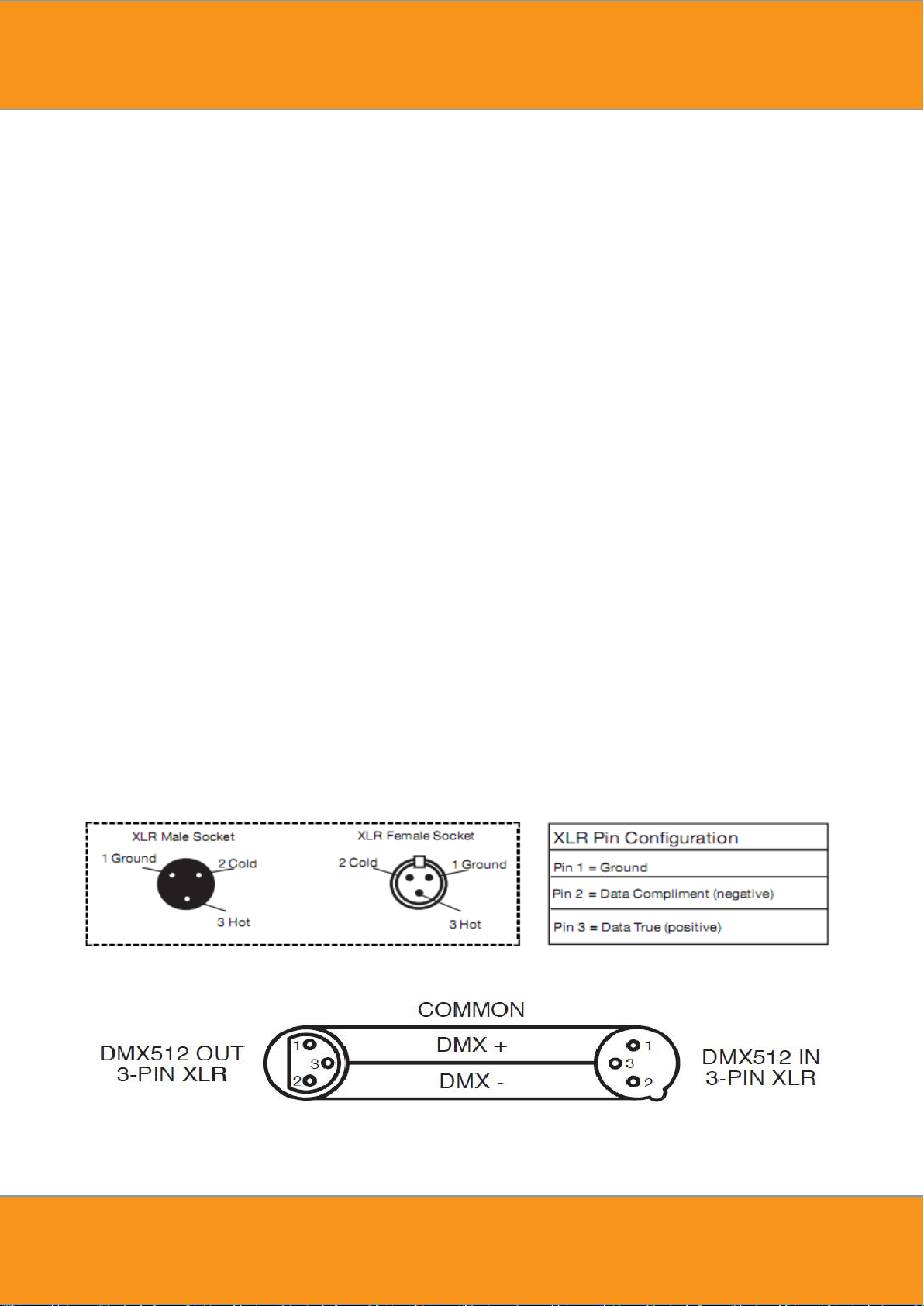
10. XLR cable connecting
XLR cable:
The standard connection way of the XLR is: one end connects to the male plug, and the other
connects to the female. As below: pin 1: ground, pin 2: negative signal, pin 3: positive signal
Page 20
17
PROBLEM
REASON AND ACTION
The lightin g can’t be
started normally
Check the power connection is correct or not.
Please detect the voltage.
Power supply is damaged or incorrect connected. Call a
qualified personnel to fix it.
Connection of control board is not correct. Call a qualified
personnel to fix it.
Out of console’s
control
is connected correctly or not. It means having signal if it shows
twinkling of the decimal point which in the lower right corner
of the screen when exiting the screen saver.
Please check the DMX address setting of lighting is correct or
not.
Check【CHMD】setting is correct or not.
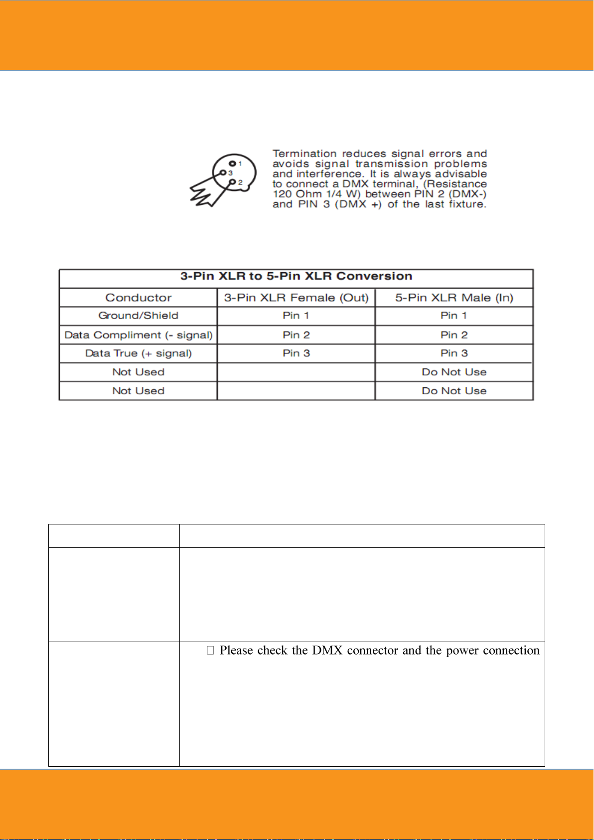
Note:In order to avoid failures and interference signal transmission,we connect a
Resistance 120Ω(1/4W)at the end of the DMX connecting as below:
The Conversion between 3 pin and 5 pin XLR
If the output cable of DMX512 controller is the 5PIN, please use 1pc 5PIN to 3PIN cable
11. Trouble Shooting
Page 21
18
Please check whether the DMX line is near to the high voltage
wire or not. In that case, it will damage or interfere the DMX
electric circuit.
The beam appears
dim ,the brightness
declines obviously
Check whether the 【CAL】is started or not and the set value is
too small.
Check whether the【POW】is in over temperature protection
situation or not, if yes, please take measures for ventilation.
Page 22

Das Lichttechnikhaus Vertriebs GmbH
Rudolf-Diesel-Str. 3, D-89312 Günzburg
Telefon +49 (0) 82 21 207 98-0
 Loading...