


This page was intentionally left blank.

Altivar Process 600
Introduction
variable speed drives
Target Markets
Applications
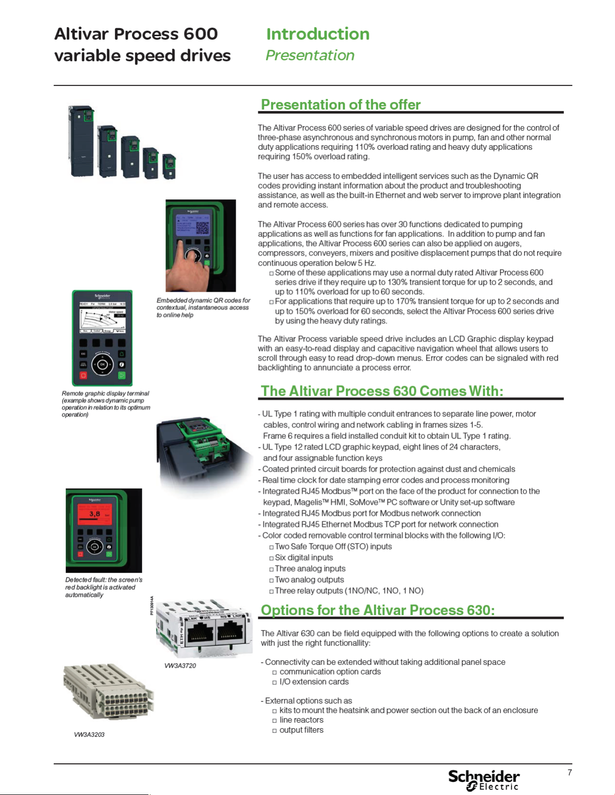
The Altivar Process 600 series of variable speed drives has over 30
functions dedicated to pumping applications as well as functions for fan
and simple material handling applications.
The Altivar Process was designed for the following markets and
applications.
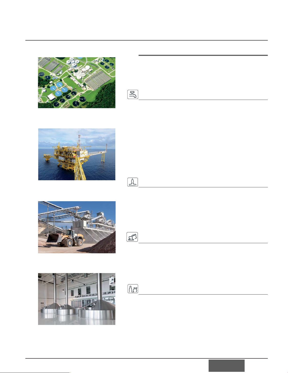
Water & Wastewater applications
Ŷ Water Intake - surface pumps
- borehole pumps
Ŷ Treatment - aeration blowers
- disinfection dosing pumps
- ventilation fans
Ŷ Storage & Transportation - distribution pumps
- pressure booster pumps
Ŷ Lift Station - submersible pumps
Ŷ Plant Influent - submersible pumps
- screw pumps
Ŷ Treatment - aeration blowers
- sludge conveying
- gas compression
- dosing pumps
- odor ventilation
Oil & Gas applications
Ŷ Extraction - submersible pumps
- liquid injection pumps
Ŷ Treatment - liquid treatment pumps
- refinery pumps
- ventilation fans
Ŷ Storage - distribution pumps
- pressure booster pumps
Ŷ Transport - pipeline booster pumps
- compressors
Mineral, Mining & Metals applications
Ŷ Extraction - ventilation fans
- de-watering pumps
- mine shaft pumps
Ŷ Treatment - filtration pumps
- refinery pumps
- cooling fans
- induced draft fans
- mixers
- exhaust fans
Food & Beverage applications
Ŷ Material receiving - ventilation fans
- simple conveying
Ŷ Processing - mixing pumps
- boiler pumps
- condensate pumps
- solids handling
- ventilation fans
- liquid pumps
- cooling tower fan
- dryer fans
Ŷ Transport - pipeline booster pumps
- compressors
5

Altivar Process 600
Introduction
variable speed drives
Product Range
Product range
The Altivar Process 600 series of variable speed drives are available in a variety of
enclosures and cover a wide range of motor power ratings.
The Altivar Process 630 range, packaged in 6 frame sizes, is a global offer available
worldwide and designed to meet worldwide standards and certifications.
The range includes:
Ŷ 200 - 240Vac, 1-60 HP, UL Type 1 rating
Ŷ 200 - 240Vac, 75-100 HP, IP00 rating, UL Type 1 rating with option conduit kit
Ŷ 400 - 480Vac, 1-125 HP, UL Type 1 rating
Ŷ 400 - 480Vac, 150 - 250 HP, IP00 rating, UL Type 1 rating with option conduit kit
The Altivar Process 660 range, with availability beginning in 3rd quarter 2015, is a
regional offer designed to meet standards and certifications applicable in the USA.
The range includes:
Ŷ 200 - 240Vac, 1-60 HP, available with
- UL Type 1, UL Type 12, or UL Type 3R enclosures
Ŷ 400 - 480Vac, 1-125 HP, available with
- UL Type 1, UL Type 12, or UL Type 3R enclosures
Ŷ 400 - 480Vac, 150 - 1100 HP
- UL Type 1, UL Type 12
Options for the Altivar Process 660 range include circuit breaker disconnects, service
entrance ratings, options for push buttons, pilot lights, and other items required for
the targeted markets.
6
Altivar Process 600
Introduction
variable speed drives
Energy dashboard
Presentation
Integrated Functions
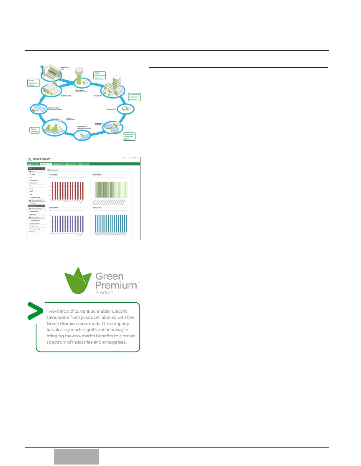
Operational Intelligence delivers value through process visibility.
The Altivar Process incorporates features that provide process monitoring and
visibility.
- Power measurement capable of 5% accuracy for energy management.
- Advanced integrated web server.
- Web server secured with Achilles Level 2 certification.
- Web pages can be quickly customized with ready-to-use-widgets to create different
dashboards.
- Process data and status tables, charts and graphs can be accessible with any
HTML5 browser.
- Data can be logged for export in .csv formatted files.
- Accepts 5 operating points and the BEP (Best Efficiency Point) of a pump curve to
provide feedback on operating efficiency.
Through system and equipment condition monitoring, Altivar Process can help ensure
applications are performing at optimum efficiency.
Embedded Guidance provides direction that improves uptime
Built-in functions simplify set-up and provide quick understanding.
- A Simply Start menu guides the operator through the initial set-up.
- ‘My Menu’ allows users to select their key parameters to store in this menu.
- A ‘Modified Parameters’ menu stores the last 10 parameters that have been
modified.
- Parameters are grouped by application configuration, motor parameters, commun-
cation setting parameters and display parameters. Any single or multiple parameter
group can be copied into the keypad to be downloaded into other drives.
- Integrated pump functions and pump protection features can be quickly config ured.
- Error codes can be date and time stamped to aid in diagnostics.
- QR code access to technical documentation, and diagnostic information on mobile
devices.
- A static QR code located on the drive provide part number specific information.
- The drive’s ability to dynamically generate QR codes based on error conditions
helps solve issues immediately by directing operators to specific technical
information and support information.
- These QRs can also assist in making contact with a Schneider Electric Customer
Care center when needed.
This embedded guidance can speed up start-up, troubleshooting and maintenance
while reducing downtime and its related costs.
A Reliable and Sustainable platform for long-term dependable service
The Altivar Process represents the latest in reliable and sustainable design technology. The drive complies with all aspects of Schneider Electric’s industry leading
“Green PremiumTM” standard for sustainable and eco conscious product design,
incorporating 70 percent or greater of recyclable materials and is in compliance with
RoHS 2 and REACH standards. Other key aspects are:
- Conformal coatings to provide resistance to chemical pollution. This provides
resistance against: sea salts, sulphur dioxide, hydrogen sulphide, chlorine, hydro gen chloride, hydrogen fluoride, ammonia, ozone, and nitrogen oxides.
- Conformal coatings to provide resistance to air born pollution. This provides resis tance against debris such as dust and sand.
- Stop and Go capability: Power consumption can be reduced up to 60%,
depending on the power size, while the drive is in standby, waiting for a run
command. This is accomplished by powering down cooling fans, display
backlighting, and the power section of the drive.
- Integrated safety inputs minimize external components and wiring.
- Ability of the drive to continuously operate at 50 degrees Celsius.
Long operating life and reliable service have been lasting hallmarks of the Altivar
drives family for more than 30 years. That tradition continues with the Altivar Process
drive.
8
Altivar Process 600
Introduction
variable speed drives
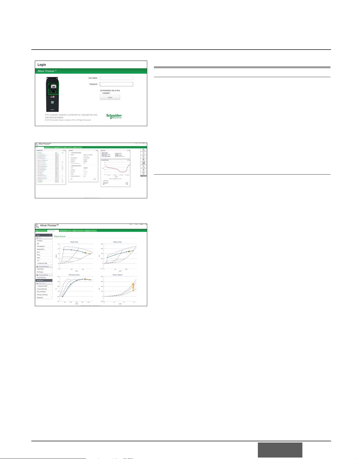
Login screen
Customizable widgets
Presentation
Web Server
Presentation
The Web server can be accessed:
Ŷ For a drive not connected to an Ethernet network:
- Direct connection via an Ethernet cable or the Schneider Electric
dongle (the drive then appears as a network device)
Ŷ For a drive connected to an Ethernet network:
- from any point on the network by entering the drive IP address
Ŷ The Web server is used for::
- Commissioning the drive (setting configuration parameters and enabling the
main functions)
- Monitoring energy and process data, as well as drive and motor data
- Diagnostics (drive status, file transfer, detected errors and warnings logs)
Description
The Web server is structured around 5 tabs.
Ŷ “My dashboard” tab:
- Configurable using a wide choice of widgets; groups all the information
selected by the user on one page
Ŷ “Display” tab:
- Monitors energy indicators, efficiency, and performance
- Displays process data such as optimum pump operation
- Monitors drive parameters and status
- Shows the I/O state and assignment
TM
WiFi
Pump curves
Ŷ “Diagnostics” tab:
- Drive status
- Time and date-stamped warning and detected errors logs
- Network diagnostics
- Access to drive self-tests
Ŷ “Drive” tab:
- Access to the main drive adjustment parameters with contextual help
Ŷ “Setup” tab:
- Network configuration
- Access management
- Transferring and retrieving drive configurations
- Exporting data acquisition files and logs
- Customizing pages (colors, logos, etc.)
Ŷ Other characteristics:
- Ease of connection via the RJ45 port or WiFi connection
- Password-protected authentication (modifiable password; access rights can
be configured by administrator)
- No downloads or installation necessary
- Web server can be disabled
Ŷ Works in a similar way on PCs, iPhones, iPads, Android systems, and the main web
browsers:
- Internet Explorer
- Google Chrome
- Mozilla Firefox
- Safari
®
(version 5.1.7 or higher)
®
(version 8 or higher)
®
(version 11 or higher)
®
(version 4 or higher)
9

Altivar Process 600
Introduction
variable speed drives
Altivar Process DTM in Unity
Presentation
DTM
Presentation
Using FDT/DTM technology it is possible to configure, control, and diagnose Altivar
Process drives directly in Unity Pro and SoMove software by means of the same
software brick (DTM).
FDT/DTM technology standardizes the communication interface between field devices
and host systems. The DTM contains a uniform structure for managing drive access
parameters.
Specific functions of the Altivar Process DTM
Ŷ Offline or online access to drive data
Ŷ Drive firmware updates
Ŷ Transfer of configuration files from and to the drive
Ŷ Customization (dashboard, My Menu, etc.)
Ŷ Acces to drive parameters and option cards
Ŷ Oscilloscope function
Ŷ Graphic interface to assist with configuration of the Altivar Process pump
functions
Ŷ Energy and process dashboards
Ŷ Graphic display of system operation and comparison with optimum operation
(pump curves)
Ŷ Detected errors and warnings logs (with timestamping)
SoMove software
Ŷ Advantages of the DTM library in Unity Pro:
- Single tool for configuration, commissioning, and diagnostics
- Network scan for automatic recognition of network configuration
- Ability to add/remove, copy/paste configuration files from other drives in
the same architecture
- Single input point for all parameters shared between the ePAC
(programmable automation controller) and the Altivar Process drive
- Creation of drive profiles for implicit communication with the ePAC as well
as dedicated profiles for programs with DFBs (derived function blocks)
- Integration in the fieldbus topology
- Drive configuration is an integral part of the Unity Pro project file (STU) and
the archive file (STA)
- Advantages of the DTM library in SoMove:
- Drive-oriented software environment
- Wired connection to the Ethernet communication port
- Standard cable (file transfer performance)
- Third-party software and downloads:
- The Altivar Process DTM library is a flexible, open, and interactive tool that
can be used in a third-party FDT.
- DTMs can be downloaded from our website
10
Altivar Process 600
Introduction
variable speed drives
Pump Functionality
Flow Limitation
Allows user to limit the flow of the system to a configured value.
Sleep/Wake Up
Manages periods where demand is low and main pumps do not need to remain
running. It saves energy and prevents premature aging. The user can select the
sleep mode activation: on sensor value, on switch or external condition, on speed,
or on power level.
Sleep Boost
When entering in Sleep mode, a boosting phase allows increasing pressure just
before stopping the pump. It prevents from quick restart in case of low demand.
Low Demand
Define periods of the application where water demand is low in order to save
energy.
Jockey Pump Control
During Sleep mode, a Jockey pump can be started to maintain emergency service
pressure or to meet a low demand.
Anti-Jam
Removes clogging substances from the pump impellers with quick forward and
reverse operation. It can be triggered automatically or manually.
Advance Sleep Checking
Used to periodically monitor demand when pump curve is flat and flow switch or
meter isn’t installed
Pipe Cleaning
Used to start the pump periodically to avoid sedimentation in the pump housing.
Centrifugal Pump Start & Stop
Defines speed profile & control the start & stop of the pump.
Multi-Pump Control (Booster) Drive to Drive
Define control of several pumps
Sensor Management
Define how the drive I/O will be used to manage pressure sensor or flow sensor
inputs.
Process Control (PID)
Maintains a process at a given pressure or flow reference in the water network.
Level Control
Used to manage an upper level limit or lower level limit of a liquid in a tank.
Friction Loss Compensation
Helps to maintain constant pressure by monitoring flow in order to compensate
pressure losses over pipes by estimating the pressure drop due to friction.
Application Modes
Define running modes of the application, control inputs and monitoring outputs
related to application.
Priming Pump Control
The priming pump maintains a supply to the inlet of the main pump by running
before the lead pump starts.
Pipe Fill
Used on the start cycle to prevent water hammer and associated mechanical
stresses in pipes when a system is filled in too quickly.
Outlet Pressure Protection
Min Pressure (detection of Pipe Burst, low outlet pressure while pump is loaded)
Max Pressure (prevention of Pipe Burst, detect running outside normal working
area)
11

Altivar Process 600
Introduction
variable speed drives
Pump Functionality
Application Units
Define units used in applications, including pressure, flow rate, temperature, and
currency.
Centrifugal Pump Characteristics
Define characteristics & configuration of a centrifugal pump
Sensorless Flow Estimation
Provides flow estimation using predefined pump curves HQ (head vs flow) or PQ
(power vs flow) entered by the user. It’s designed to work on single pump systems
without external sensor input.
PID Auto Tuning
Auto tuning of PID parameters.
Pump Cyclic Start Protection/ Pump Cycle Monitoring
Limits the number of restarts in a dedicated time period in order to avoid excess
wear to the pump.
12
Altivar Process 600
Introduction
variable speed drives
Pump Functionality
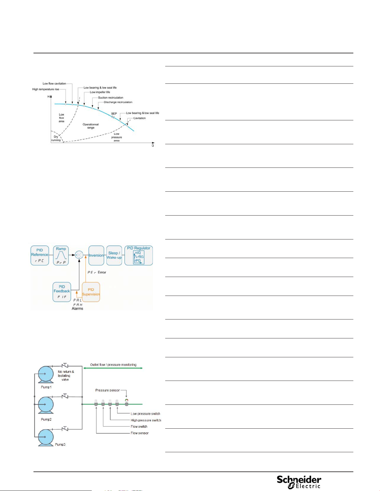
Cavitation Pump Protection
Functions used to prevent cavitation which can damage the pump impeller, reduce
flow, create vibration, and increase energy consumption.
Dry Running Pump Protection
Detects pump operation in a dry running condition to avoid severely damaging or
destroying the pump.
No Flow/ Low Flow Pump Protection
Detects pump operation at no flow or low flow to avoid severely damaging or
destroying the pump by overheating
PID Feedback Supervision
Keep pump running point in right running area. Prevention of burst pipe
High Flow Protection
Detection of Pipe Burst. Detect running outside normal working area
Inlet Pressure Protection
Protects the pump against low inlet pressure. When the inlet pressure goes below
the settable pressure, the applied pressure setpoint is decreased by the drive itself
to prevent cavitation. If the pressure setpoint is reduced, the pump speed will also
decrease.
Outlet Pressure Protection
This protection provides outlet “high pressure” and “low pressure” alarms. Used to
prevent pipe system damage or to detect burst pipes.
Low Pressure Pump Protection
Detects pump operation at low pressure in order to avoid pump damage due to
cavitation.
13

Altivar Process 600
Introduction
variable speed drives
Pump Functionality
Total Quantity
The estimated total cumulated quantity (volume or mass) when a flow rate sensor is
used. Installation related Cumulated Values & Counts are recorded for the full life of
the installation and can be reset or modified (e.g. in case of device replacement) by
customer.
Outlet Pressure
The measured pressure at outlet/discharge of the pump system or installation.
Inlet Pressure
The measured pressure at inlet/suction of the pump system or installation.
Level
The measured level of the installation when level control is activated.
Installation Flow Rate
The measured total flow rate of the installation.
Pump Status
Status of the pump controlled by VSD (Running, Stopped, Anti-Jam, Fault detected)
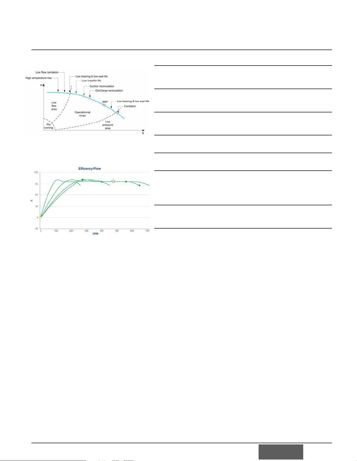
Pump Curves
User has the possibility to input 6 points from a pump curve (including BEP) for
better control and monitoring of the process. Curves can be in Head vs Flow,
Power vs. Flow, or Power vs Speed
Energy Consumption
Allows the display of several values: Instantaneous input power, Input energy
consumed, Instantaneous output power, Cumulated output energy consumed. They
can be logged and viewed by hour, week, month, and year. It can also estimate the
energy bill based on usage and rate as input by the user.
Power Drift Detection
Can manage alarms to alert user when power consumed is either too low or too high
compared to expected value
Energy Saved
The drive will display energy saved while the motor is running.
Pump Thermal Monitoring
Helps prevent equipment damage due to high temperature by monitoring the real
temperature by the drive.
Motor Thermal Monitoring
Helps prevent motor damage from overheating by an estimation of the thermal state
of the motor.
14

Altivar Process 600
Specifications
variable speed drives
Electrical Specifications
Input power
Drive output voltages
Output frequency range
Configurable switching
frequency
Speed range
Speed accuracy
Torque accuracy
Braking torque
Maximum transient
current
Voltage V 200 - 15%...240 + 10% three-phase for ATV 630pppM3
Frequency Hz 50 - 5%...60 + 5%
ATV630U07M3...D45M3
ATV630075N4…D75N4
ATV630U07M3...D22M3
ATV630U07N4...D45N4
ATV630D30M3...D45M3
ATV630D55N4...D90N4
ATV630D55M3...D75M3
ATV630C11N4...C16N4
For a torque variation of 0.2
Tn to Tn
Normal Duty Rating 110% of the nominal drive current for 60 s (typical value) with a minimum duty cycle of 10 minutes.
Electrical
380 - 15%...480 + 10% three-phase for ATV 630ppppN4
500 - 15%…690 + 10% three-phase for ATVpppY
V Maximum three-phase voltage equal to line supply voltage
Hz 0.1...500 Hz
kHz Nominal switching frequency: 4 kHz without derating in continuous operation.
Adjustable during operation from 1…16 kHz
Above 4 kHz, see the derating curves in the Installation Manual.
kHz Nominal switching frequency: 2.5 kHz without derating in continuous operation.
Adjustable during operation from 1…8 kHz
Above 2.5 kHz, see the derating curves in the Installation Manual.
kHz Nominal switching frequency: 2.5 kHz without derating in continuous operation.
Adjustable during operation from 2.5…8 kHz
Above 2.5 kHz, see the derating curves in the Installation Manual.
Asynchronous motor:
Ŷ 1…100 in open-loop mode without encoder feedback
Synchronous motor:
Ŷ 1…50 in open-loop mode without encoder feedback
± 10% of nominal slip, without encoder feedback
± 15% in open-loop mode without encoder feedback
30% of nominal motor torque without braking resistor (typical value)
130% of the nominal drive current for 2 s (typical value)
Motor control profiles
Heavy Duty Rating 150% of the nominal drive current for 60 s (typical value) with a minimum duty cycle of 10 minutes.
170% of the nominal drive current for 2 s (typical value)
Asynchronous motor:
Ŷ Voltage/frequency: quadratic, or 2 point or 5 points
Ŷ Voltage/frequency optimized for energy savings
Synchronous motor:
Ŷ Vector control for permanent magnet motors
15

Altivar Process 600
Specifications
variable speed drives
Electrical Specifications (continued)
Slip compensation
Drive noise level
ATV630D11M3 dBA 65
ATV630D15M3...D22M3 dBA 75
ATV630D30M3...D45M3 dBA 78
ATV630D55M3...D75M3 dBA 76
ATV630D15N4...D22N4 dBA 65
ATV630D30N4...D45N4 dBA 75
ATV630D55N4...D90N4 dBA 78
ATV630C11N4...C16N4 dBA 76
Indicator
Electrical impedance
Motor protection
Dielectric strength
ATV630U07M3...U55M3
ATV630U07N4...C13N4
ATV630U75M3...D55M3
ATV630C16N4
ATV630D75M3 Integrated DC choke
Electrical isolation
Acceleration and deceleration ramps
Braking to a standstill
Main drive protection and protection
features
ATV630pppM3 Between ground and power terminals: 2830 V c
Electrical
Automatic. Can be suppressed or adjusted.
Conforming to directive 86-188/EEC
1 LED red for presence of voltage
4 LEDs dual color for communication module status
3 LEDs dual color for embedded communication status
3 LEDs for local diagnostic
Integrated DC Choke
Inductance of approximately 1.5-2%
Integrated DC choke
Inductance of approximately 2.5-3%
Inductance of approximately 4%
Between power and control (inputs, outputs, power supplies)
Ramp profiles:
Ŷ Linear, can be adjusted separately from 0.01 to 9000 s
Ŷ S, U or customized
Automatic adaptation of deceleration ramp time if braking capacities exceeded,
programmable inhibition of this adaptation.
By DC injection:
Ŷ By a command on a programmable logic input
Ŷ Automatically as soon as the estimated output frequency drops to < 0.1 Hz, period
adjustable from 0 to 60 s or continuous, current adjustable from 0 to 1.1 In. for
normal duty rating and 0 to 1.4 In. for heavy duty rating.
Thermal protection:
Ŷ Drive overtemperature
Ŷ On the power stage
Protection against:
Ŷ Internal short-circuits between motor phases
Ŷ Overcurrents between output phases and ground
Ŷ Overvoltages on the DC bus
Ŷ Loss of follower signal
Ŷ Exceeding maximum speed setting
Ŷ Line supply overvoltage and undervoltage
Ŷ Input phase loss, with three-phase input
Class 10 motor thermal protection integrated in drive via continuous calculation of I
taking speed
into account:
Ŷ The motor thermal state is saved when the drive is powered down.
Ŷ Function can be modified depending on the type of
motor (force-cooled or self-cooled).
Protection against motor phase loss
Protection with user supplied PTC probes Safe Torque Off
2
t
Insulation resistance to ground
Frequency resolution
16
ATV630ppppN4 Between ground and power terminals: 3535 V c
Between ground and power terminals: 3110 V c
> 1 M:(electrical isolation) 500 V c for 1 minute
Display units Hz 0.1
Analog inputs Hz 0.012/50 Hz (12 bits)

Altivar Process 600
Specifications
variable speed drives
Environmental
Environmental Specifications
Vibration resistance
Shock resistance
Maximum ambient
pollution
Definition of insulation
Environmental
conditions
Around the device
Relative humidity
Ambient air
temperature around the
device
Maximum operating
altitude
Operating position Vertical position +/- 10 degrees
ATV630U07M 3...D45 M3
ATV630U07N 4...D 90 N4
ATV630D55M3...D75M3
ATV630C11N4...C16 N4
ATV630U07M3...D45M3
ATV630U07N4...D90N4
ATV630D55M3...D75M3
ATV630C11N4...C16N4
ATV630U07M3...D75M3
ATV630U07N4...C16N4
ATV630U07M3...D75M3,
ATV630U07N4...C16N4
ATV630U07M3...D75M3
ATV630U07N4...C16N4
Operation °C - 10…+ 50 without derating
Storage °C - 40…+ 70
ATV630U07M3...D75M3
ATV630U07N4...C16N4
1.5 mm peak to peak from 2…13 Hz, 1 gn from 13…200 Hz, conforming to IEC/EN 60068-2-6
1.5 mm peak to peak from 3…10 Hz, 0.6 gn from 10…200 Hz, conforming to IEC/EN 60068-2-6
15 gn for 11 ms conforming to IEC/EN 60068-2-27
7 gn for 11 ms conforming to IEC/EN 60068-2-27
Degree 2 conforming to IEC/EN 61800-5-1
Degree 3 in accordance with UL marking conforming to UL840
Chemical pollution resistance to class 3C3 per EN/IEC 60721-3-3.
This provides resistance against: sea salts, sulphur dioxide, hydrogen sulphide, chlorine,
hydrogen chloride, hydrogen fluoride, ammonia, ozone, and nitrogen oxides.
Air borne debris pollution resistance to class 3S3 per EN/IEC 60721-3-3.
This provides resistance against air borne debris such as dust and sand.
% 5…95% without condensation or dripping water conforming to IEC 60068-2-3
Up to 60 with derating per the derating curves in the Installation Manual.
m 1000 without derating
1000…4800 derating the current by 1% per additional 100 m.
Limited to 2000 m for the “Corner Grounded” distribution network
17

Altivar Process 600
Specifications
variable speed drives
Certifications and Compliance
Certifications and Compliance
Conformity to
standards
Protection UL508C (Standard for Power Conversion Equipment)
Conducted
EMC
emissions for
drives
ATV630U07M3...D75M3 No integrated EMC filter
ATV630U07N4...C16N4 Integrated EMC filter meets IEC/EN 61800-3:
e marking The drives are marked e according to the European low voltage (2006/95/EC) and EMC
Product certifications
Altivar Process drives have been developed to conform to the strictest standards and the
recommendations relating to electrical industrial control devices (UL,IEC, EN), in particular:
UL508C, UL50, IEC/EN 61800-5-1, and IEC/EN 61800-3.
UL 50 (Standard for Enclosures for Electrical Equipment)
IEC 61000-3-12 (Harmonic standard)
IEC/EN 61800-3, Environments 1 and 2 (EMC requirements and specific test methods)
IEC/EN 61000-4-2 level 3 (electrostatic discharge immunity test)
IEC/EN 61000-4-3 level 3 (radiated, radio-frequency, electromagnetic field immunity test)
IEC/EN 61000-4-4 level 4 (electrical fast transient/burst immunity test)
IEC/EN 61000-4-5 level 3 (surge immunity test)
IEC/EN 61000-4-6 level 3 (immunity to conducted disturbances, induced by radio-frequency
fields)
IEC/EN 61000-4-11 (voltage dips, short interruptions and voltage variations immunity tests)
EN/IEC 61800-5-1 (Standard for Adjustable Speed Electrical Power Drive Systems)
EN/IEC 62061 EN ISO 13849-1 (functional safety)
IEC 61508 (functional safety)
IEC 60721-3 (classification of environmental conditions)
IEC/EN 61800-3, environments 1 and 2, categories C2 and C3
Ŷ Category C3 with up to 150 m of cable
(89/336/EEC) dir
UL 508C, UL File E116875, CSA, TUV, REACH
ectives
Degree of protection
ATV630U07M3...D45M3
ATV630U07N4...D90N4
ATV630D55M3...D75M3 w/ optional
conduit kit
ATV630C11N4...C16N4 w/ optional
conduit kit
ATV630D55M3...D75M3
ATV630C11N4...C16N4
UL Type 1 conforming to UL 50: Standard for enclosures for Electrical Equipment.
IP 21 conforming to IEC 60529
IP21 conforming to IEC 61800-5-1
IP 00 conforming to IEC 60529
IP 00 conforming to IEC 61800-5-1
18

Altivar Process 600
Specifications
variable speed drives
I/O and Control Specifications
Description Terminal Electrical Characteristics
Available internal
supplies for analog
inputs
For external + 24 V
power supply
Analog input
Analog I/O
Common
Analog output
Analog I/O
Common
10 V, 24 V Output supply for Analog Input:
P24 External input supply +24 Vdc
0 V 0 V for P24
AI1, AI2, AI3 Software-configurable V/A : voltage or current analog input
COM 0 V for analog inputs
Other inputs Available on I/O option cards
AQ1, AQ2 AQ: Analog output software-configurable for voltage or current
COM 0 V for analog outputs
I/O and Control Specifications
10 V
Ŷ 10.5 Vdc
Ŷ Tolerance ± 5%
Ŷ Current: maximum 10 mA
Ŷ Short circuit protected
24 V
Ŷ +24 Vdc
Ŷ Tolerance: minimum 20.4 Vdc, maximum 27 Vdc
Ŷ Current: maximum 200 mA for both 24 Vdc terminals
Ŷ Terminal protected against overload and short-circuit
Ŷ In Sink Ext position, this supply is powered by external PLC supply
Ŷ Tolerance: minimum 19 Vdc, maximum 30 Vdc
Ŷ Current: maximum 1.25 A
Ŷ Voltage analog input 0...10 Vdc, impedance 30 k:,
Ŷ Current analog input X-Y mA by programming X and Y from 0...20 mA, with impedance 250 :
Ŷ Maximum sampling time: 5 ms ± 1 ms
Ŷ Resolution 12 bits
Ŷ Accuracy: ± 0.6% for a temperature variation of 60°C
Ŷ Linearity ± 0.15% of maximum value
Software-configurable for sensor inputs: PT1000 or KTY84 or PTC or Water level
sensor
Ŷ PT100
v 1 or 3 thermal sensors mounted in series (configurable by software)
v Sensor current: 5 mA
v Range –20/200°C
v Accuracy +/– 4°C for a temperature variation of 60°C
Ŷ PT1000
v 1 or 3 thermal sensors mounted in series (configurable by software)
v Thermal sensor current: 1 mA
v Range –20/200°C
v Accuracy +/– 4°C for a temperature variation of 60°C
Ŷ KTY84
v 1 thermal sensor
v Thermal sensor current: 1 mA
v Range –20/200°C
v Accuracy +/– 4°C for a temperature variation of 60°C
Ŷ PTC
v 6 sensors maximum mounted in series
v Sensor current: 1 mA
v Nominal value: < 1.5 k:
v Overheat trigger threshold: 3k:
v Overheat reset threshold: 1.8 k:
v Protected for low impedance < 50 :
Ŷ Water Level Sensor
Sensitivity: 0...1 M:, adjustable by softwar
v
v W
ater level sensor current: 0.3 mA...1 mA maximum
v Adjustable delay: 0...10 s
Ŷ Voltage analog output 0...10 Vdc, minimum. Minimum load impedance 470 :,
Ŷ Current analog output X-Y mA by programming X and Y from 0...20 mA, maximum load impedance 500 :
Ŷ Maximum sampling time: 10 ms ± 1 ms
Ŷ Resolution 10 bits
Ŷ Accuracy: ± 1% for a temperature variation of 60°C
Ŷ Linearity ± 0.2%
e
19


Altivar Process 600
variable speed drives
Specifications
Integrated communicaton ports
Modbus protocol
Type of connection Modbus RJ45 port on face of product Modbus RJ45 network port
Structure
Services
Physical interface 2-wire RS 485
Transmission mode RTU
Transmission speed Configurable via the display keypad or the
Format Fixed = 8 bits, even parity, 1 stop Configurable via the display keypad or the
Polarization No polarization impedances
Address 1 to 247, configurable via the terminal or the SoMove PC software.
Device profiles 2 profiles: CiA 402 (“Device Profile Drives and Motion Control”) and I/O profile
Messaging Read Holding Registers (03) 63 words maximum
Communication monitoring Can be inhibited.
TM
SoMove
9600 bps or 19200 bps
These should be provided by the wiring system (for example, in the master)
3 addresses can be configured in order to access the drive data, the “Controller Inside”
programmable card and the communication card respectively.
These 3 addresses are identical for the connector and network ports.
Write Single Register (06)
Write Multiple Registers (16) 61 words maximum
Read/Write Multiple Registers (23) 63/59 words maximum
Read Device Identification (43)
Diagnostics (08)
“Time out,” which can be set between 0.1 s and 30 s
PC software:
Configurable via the display keypad or the
SoMove PC software:
4800 bps, 9600 bps, 19200 bps or 38.4 kbps
SoMove PC software:
- 8 bits, odd parity, 1 stop
- 8 bits, even parity, 1 stop
- 8 bits, no parity, 1 stop
- 8 bits, no parity, 2 stop
CANopen protocol
Structure
Services
Physical Interface RJ45
Application Modbus TCP
Transport TCP/UDP
Network IP protocol V4 and V6
Link Ethernet
Transmission Speed 10/100 Mbits/s
Connections Up to 32 concurrent TCP/IP and/or TCP/UDP connections
Operating Modes Fixed, BOOTP, or DHCP
Messages DHCP?
I/O Scanning 32 in, 32 out, configurable contiguous memory locations
Profiles Native CiA402 - IEC61800-7, I/O profile
FDR Automatic data configuration for replaced devices
Web Server Configuration and diagnostics via defined page:
My Dashboard: allows customer defined views
Display: data views in table and graphical formats
Diagnostics: error code and self-evaluation
Drive: parameter configuration
Set-up: guided set-up configurations
21

Altivar Process 600
variable speed drives
Additional Application Information
Using Altivar Process 600 drives with
synchronous motors
Using special motors at high-speed
Using a motor at overspeed
Power of self-cooled motor greater than the
drive power
Connecting motors in parallel
Using a motor at constant torque up to
87/104 Hz
Altivar Process drives are also suitable for powering synchronous motors with sinusoidal electromotive force. This
drive/motor combination makes it possible to obtain remarkable accuracy and maximum torque.
The design and construction of synchronous motors are such that they offer enhanced power density, high efficiency,
and high-end torque in a compact footprint.
Driving a synchronous motor with sinusoidal electromotive force without speed feedback.
The entire range of Altivar Process variable speed drives can be used to power a synchronous motor with sinusoidal
electromotive force without speed feedback. The performance level achieved is then comparable to that obtained
with an asynchronous motor in sensorless flux vector control.
These motors are designed for constant torque applications with high frequency ranges. The Altivar Process drive
supports operating frequencies of up to 500 Hz. Through their design, this type of motor is more sensitive to
overvoltages than a standard motor.
Various solutions are available:
Ŷ Overvoltage limitation function
Ŷ Output filters
The drive’s 5-point voltage/frequency control ratio is particularly well-suited as it avoids resonance.
When using a standardized asynchronous motor at overspeed, check the mechanical overspeed characteristics of
the selected motor with the manufacturer. Above its nominal speed corresponding to a frequency of 50/60 Hz, the
motor operates with a decreasing flux, and its torque decreases significantly. The application must be able to permit
this type of low-torque, high-speed operation.
1. Machine torque (degressive torque)
2. Machine torque (low motor torque)
3. Continuous motor torque
Typical applications: wood-working machinery, polishing and cutting machines.
This motor-drive combination makes it possible to use a self-cooled motor for a greater speed range in continuous
operation. The use of a motor with a higher power rating than that of the drive is only possible if the current drawn by
this motor is less than or equal to the nominal drive current.
Note: Limit the motor power to the standard rating immediately above that of the drive.
Example: On a single machine, the use of a 2.2 kW drive combined with a 3 kW motor means that the machine can
operate at its nominal power (2.2 kW) at low speed.
1. Motor power = drive power = 2.2 kW
2. 2.2 kW drive combined with a 3 kW motor: greater speed range at 2.2 kW
The nominal current of the drive must be greater than or equal to the sum of the currents of the motors to be controlled.
In this case, provide external thermal protection for each motor using probes or thermal overload relays. For cable
runs over a certain length, taking account of all the tap links, it is advisable either to install an output filter between the
drive and the motors or to use the overvoltage limitation function.
If several motors are used in parallel, there are two possible scenarios:
Ŷ The motors have equal power ratings, in which case the torque characteristics will remain optimized after the
drive has been configured
Ŷ The motors have different power ratings, in which case the torque characteristics will not be optimized for all the
motors
A 400 V, 50 Hz motor in
In this particular case, the initial motor power and the power of the first associated drive are multiplied by (it is
therefore important to select a drive with a suitable rating).
Example: A 2.2 kW 50 Hz motor in
Note: Check the overspeed operating characteristics of the motor.
Application Information
Çconnection can be used at constant torque up to 87 Hz if it is in U connection.
Ç connection supplies 3.8 kW at 87 Hz with a U connection.
22

Altivar Process 600
variable speed drives
Application Information
Using special motors
ATEX motors in an explosive atmosphere
explosive
Resistive rotor asynchronous motors
Switching the motor at the drive output
Test on a low power motor or without a
motor
Special brake motors: tapered rotor or flux bypass
The magnetic field releases the brake. This type of operation with the Altivar Process drive requires application of the
voltage/frequency ratio.
Note: The no-load current may be high, and operation at low speed can only be intermittent.
Use of the STO safety function enables the variable speed drive to provide thermal protection in the event of
excessive temperature rise of the ATEX motor, but it does not enable it to control and regulate the temperature of the
ATEX motor.
All motor types ATEX certified for use in zones 1, 21, 2 or 22, which are equipped with ATEX thermal sensors, can be
protected by the Altivar Process variable speed drive.
Different motor control ratios available on the Altivar Process drive make it possible to apply specific settings when
using high-slip motors.
The drive can be switched when locked or unlocked. If the drive is switched on-the- fly (drive unlocked), the motor is
controlled and accelerates until it reaches the reference speed smoothly following the acceleration ramp. This use
requires configuration of the automatic catching a spinning load (“catch on the fly”) and the motor phase loss on
output cut functions.
Typical applications: loss of run circuit at drive output, bypass function, switching of motors connected in parallel.
On new installations, it is recommended that the STO safety function is used.
In a test or maintenance environment, the drive can be tested without having to use a motor with the same rating as
the drive (particularly useful in the case of high power drives). This use requires deactivation of the output phase loss
function.
23

Altivar Process 600
Application Information
variable speed drives
Motor cable length
Motor Cable Length
Impact of Long Motor Cable Lengths
Long motor cable lengths between a drive and motor may cause over current
conditions, causing the drive to trip on short circuit or ground fault errors or cause
over voltage conditions that cause premature wear on the motor. These
phenomenon are often underestimated at the design and installation stage. Left
un-checked, this neglect can lead to motor breakdown and unexpected down time.
Over current conditions may be caused by capacitive coupling between motor
cables, generating enough current flow to ground, which causes the drive to trip on
ground fault errors. Also capacitive coupling between motor cable may cause the
drive to detect and trip on short circuit errors.
Over voltage conditions may be caused by the mismatched impedance of the cable
and the motor. This mismatch of impedences causes the switching frequency pulsed
output voltage from the drive to reflect back from the motor terminals. The result can
be voltages at twice the level of the DC bus or higher, which can stress the drive,
cable, motor windings and motor bearings.
Generally, longer motor cables yield higher voltages. This effect is amplified when by
using shielded cable.
Preventative Measures
There are several steps provided below, beginning with the least costly, that can be
taken to reduce nuisance trip errors and improve the life of the motor.
Ŷ Reduce the switching frequency of the drive to 2.5kHz or less.
Ŷ Use un-shielded motor cables.
Ŷ Specifiy a drive, like the Altivar Process, that has software functionality to help
manage voltage wave reflection.
Ŷ Specify motors that are NEMA MG1 Part 31 or IEC60034-25 compliant.
Ŷ Specify output load reactors (also known as motor chokes) to limit voltage rise
time
Ŷ Specify dV/dt filters to further limit voltage rise time
Ŷ Specify Sine wave filters (also known as sinus filters) that allow a smooth, lower
voltage output wave form to the motor
Recommendations Additional Filters
The following table provides guidelines when to specify additional filters
Motor Cable Length
(unshielded cable)
1 m (3.3 ft.) < Lm <50 m (164 ft.) Filter not required dV/dt filter
50 m (164 ft.) < Lm < 100 m (328.1 ft.) Filter not required Sinus filter
100 m (328.1 ft.) < Lm < 300 m (984.3 ft.) Filter not required Sinus filter
300 m (984.3 ft.) < Lm < 500 m (1640.4 ft.) dV/dt filter Sinus filter
500 m (1640.4 ft.) < Lm < 1000 m (3280.8 ft.) Sinus filter Sinus filter
Note: When calculating cable lengths for the purpose of guarding against these overvoltage situations, a shielded
cable should count as twice the length of an unshielded cable. For example, if a shielded cable is 100 meters in
actual length, it should be considered to be equal to a 200 meter length standard cable in the calculation.
Note: In applications where one drive is used to power multiple motors in parallel, the appropriate cable length
should be calculated based on the sum of all the cables. For example, if three motors in parallel are connected to
a single drive, each with a 20 meter (66 foot) cable, the total length that should be calculated in not 20 meters, but
should be 60 meters (197 feet). Precautions must be taken to protect the VSD from any unexpected tripping.
Motor Conforming to
NEMA MG1 Part 31
Motor Not Conforming to
NEMA MG1 Part 31
24


Altivar Process 600
Graphic Display
variable speed drives
Remote graphic display terminal
(example shows dynamic pump
operation in relation to its optimum
operation)
Detected fault: the screen’s red
backlight is activated
automatically
Keypad
Graphic display Keypad
This graphic display keypad is supplied with the Alivar Process drive. This keypad
can be:
Ŷ Connected and mounted on the front of the drive
Ŷ Connected and mounted on an enclosure door using a remote mounting
accessories
Ŷ Connected to a PC to exchange files via a Mini USB/USB connection
Ŷ Connected to several drives in multidrop mode
This keypad is used to:
Ŷ Control, adjust, and configure the drive
Ŷ Display current values (motor, I/O, and process data)
Ŷ Display graphic dashboards such as the energy consumption monitoring
dashboard
Ŷ Store and download configurations (several configuration files can be stored in the
16 MB memory)
Ŷ Duplicate the configuration of one powered-up drive to another powered-up drive
Ŷ Copy configurations from a PC or drive and duplicate them on another drive (the
drives must be powered on for the duration of the duplication operations)
Other keypad characteristics:
Ŷ Integrated languages covering many countries around the world
Ŷ 2-color backlit display (white and red); if an error is detected, the red backlight is
activated automatically (This function can be disabled if needed)
Ŷ Operating range: -15...50 °C/+5...122 °F
Ŷ Type 12/ IP 65 protection
Ŷ Trend curves: graphic display of changes over time in monitoring variables, energy
data, and process data
Ŷ Graphic display of a pump’s dynamic operation in relation to its optimum operation
Ŷ Embedded dynamic QR codes for providing contextual, instantaneous access to
online help (diagnostics and settings, etc.) using a smartphone or tablet
Ŷ Real-time clock with backup battery for providing data acquisition and event
timestamping functions even when the drive is stopped
Embedded dynamic QR codes for
contextual, instantaneous access to
online help
Scanning the QR code from a
smartphone or tablet
Instant access to online help
Description
Display:
Ŷ 8 lines, 240 x 160 pixels
Ŷ Displays bar charts, gauges, and trend charts
Ŷ 4 function keys to facilitate navigation and provide contextual links for enabling
functions
Ŷ “STOP/RESET” button: local control of motor stop command/clearing detected
faults
Ŷ “RUN” button: local control of motor run command
Ŷ Navigation buttons:
Ƒ OK button: saves the current value (ENT)
Ƒ Capacitive wheel dial ±: increases or decreases the value, goes to the next or
previous line
Ƒ “ESC” button: aborts a value, parameter, or menu to return to the previous
selection
Ƒ home: root menu
Ƒ information (i): contextual help
Part Number
Description Part Number Weight
Graphic display
keypad (supplied with
drive)
VW3A1111 0.200/0.441
kg/lb
27


Altivar Process 600
Accessories & Options
variable speed drives
Mounting Options
Kit for mounting heat sink & power section
external to enclosure
This kit can be used to mount the power section of the drive outside the enclosure,
which reduces the power dissipated into the enclosure.
Kits are available for frame sizes 1-5:
ATV630U07M3...ATV630D45M3
ATV630U07N4...ATV630D90N4
With this type of mounting, the enclosure size can be reduced as the enclosure
surface area needed to dissipate the heat in the enclosure is minimized. See the
selection tables for dissipated power of the drive and power dissipated in the
enclosure when using this kit to mount the heat sink and power section out the back of
the enclosure.
The back of the enclosure must be cut to accept the metal frame that comes with the
kit.
The kit includes:
b A metal frame of the right frame size for the drive rating
b Seals
b Mounting screws
b Instruction sheet
For drives Frame Size Part number Weight
ATV630U07M3...ATV630U40M3
ATV630U07N4...ATV630U55N4
ATV630U55M3...ATV630U75M3
ATV630U75N4...ATV630D11N4
ATV630D11M3
ATV630D15N4...ATV630D22N4
ATV630D15M3...ATV630D22M3
ATV630D30N4...ATV630D45N4
ATV630D30M3...ATV630D45M3
ATV630D55N4...ATV630D90N4
lbs kg
1
2
3
4
5
NSYPTDS1
NSYPTDS2
NSYPTDS3
NSYPTDS4
NSYPTDS5
6 2.7
6.8 3.1
8.2 3.7
10.1 4.6
10.8 4.9
UL Type 1 Conduit Kit
This kit can be used with the frame size 6 Altivar Process 630 to obtain a UL Type
1 rated enclosure installation. This is kit is field installed. Frame sizes 1-5 of the
Altivar 630 range come standard with a UL Type 1 rated enclosure.
This kit is available for:
ATV630D55M3…ATV630D75M3
ATV630C11N4…ATV630C16N4.
This kit provides numerous conduit entrance knockouts to properly separate incoming line power cables, output motor cables, control wiring, and any communication
cabling.
The kit includes:
Ŷ Metal casing to fit up to the bottom of the frame size 6 Altivar Process 630
Ŷ Conduit knock-outs on the bottom of the casing
Ŷ Mounting screws
Ŷ Instruction sheet
For drives Frame Size Part number Weight
lbs kg
ATV630D55M3...ATV630D75M3
ATV630C11N4...ATV630C16N4
6 VW3A9704 - -
30


Altivar Process 600
Accessories & Options
variable speed drives
VW3A3203
Maximum Wire Size: 1.0 mm2 (AWG 16)
VW3A3203
Pin Terminal Function Electric Characteristics
Soe-configurable Voltage, current, PT100,
1 SHLD Shield connection AI4
2 AI4+
Differential Analog Input 4
Depending on SW configuration
Differential Voltage measurement
3 AI4-
4 AI4+L
5 SHLD Shield connection AI5
6 AI5+
7 AI5-
8 AI5+L
PTx measurement
0...20mA measurement
AI4- reference potential for AI4+
3 wire PTx compensation
connection
Differential Analog Input 5
Depending on SW configuration
Differential Voltage measurement
PTx measurement
0...20 mA measurement
AI5- reference potential for AI5+
3 wire PTx compensation
connection
PT1000, KTY84,
PTC measurement: Voltage differential input
circuit:
Ŷ Range: -10 Vdc...+10Vdc
Ŷ Impedance: 20k:
Ŷ Resolution: 11 bit + sign bit
Ŷ Accuracy: +/- 0.6% for a temperature
variation of 60°C
Ŷ Linearity: +/- 0.15% of max. value
Current measurement:
Ŷ Range: X-Y mA by programming X and Y
from 0 to 20 mA
Ŷ Impedance: 250:
Ŷ Resolution: 10 bit
Ŷ Accuracy: +/- 0.6% for a temperature
variation of 60°C
Ŷ Linearity: +/- 0.15% of max. value
Ŷ Sampling period: 1 ms
PTx measurement: Type of PTx and mode
selected via parameter PT100, PT1000, PTC,
KTY84
Ŷ PT100:
Ƒ 1 or 3 thermal sensors mounted in series
(configurable by software)
Ƒ Thermal sensor current: 7,5 mA max
Ƒ Range: -20...200°C
Ƒ Accuracy: +/- 3°C final for a temperature
variation of 60°C
Ŷ PT1000, KTY84:
Ƒ 1 or 3 thermal sensors mounted in series
(configurable by software)
Ƒ Thermal sensor current: 1 mA max
Ƒ Range: -20...200°C
Ƒ Accuracy: +/- 3°C final for a temperature
variation of 60°C
Ŷ PTC:
Ƒ 3 or 6 thermal sensors mounted in series
(configurable by software)
Ƒ Thermal sensor current: 1 mA max
Ƒ Nominal value: <1.5 k:
Ƒ Overheat trigger threshold: 3 k:
Overheat reset threshold: 1.8 k:
Ƒ
otected for low impedance: <50 :
Ƒ pr
Ƒ detection of high impedance: >100k:
9 DQ12 Digital output 12
10 DICOM
11 DI11 Digital input 11
12 DI12 Digital input 12
13 DI13 Digital input 13
14 DI14 Digital input 14
15 DI15 Digital input 15
16 DI16 Digital input 16
17 DQCOM
18 DQ11 Digital output 11
Digital input common
Reference potential for the digital
inputs
Digital output common
Reference potential for the digital
outputs
Note: Only one VW3A3203 can be installed for one drive
The levels of the digital 24 Vdc output signals
DQ, comply with IEC/EN61131-2 standard
Ŷ Logic Type selected via DQCOM wiring
Ŷ Output voltage: d 30Vdc
Ŷ Switching current: d 100mA
Ŷ Voltage drop at 100 mA load: d 3Vdc
Ŷ Sampling period: 1 ms
The levels of the digital 24 Vdc input signals
DI, comply with IEC/EN61131-2 standard
Ŷ Logic Type selected via DICOM wiring
Ŷ Positive logic (Source): State 0 if d 5Vdc,
state 1 if t11Vdc
Ŷ Negative logic (Sink): State 0 if t16Vdc,
state 1 if d 10Vdc
Ŷ Maximum voltage: 30 Vdc
Ŷ Input current (typical): 2.5 mA
Ŷ Sampling period: 1 ms
The levels of the digital 24 Vdc output signals
DQ, comply with IEC/EN61131-2 standard
Ŷ Logic Type selected via DQCOM wiring
Ŷ Output voltage: d 30Vdc
Ŷ Switching current: d 100mA
oltage drop at 100 mA load: d
Ŷ V
Ŷ Sampling period: 1 ms
3Vdc
33

Altivar Process 600
Accessories & Options
variable speed drives
VW3A3204
Maximum Wire Size: 1.5 mm2 (AWG 16)
VW3A3204
Pin Terminal Function Electric Characteristics
Programmable Output Relay 4:
1 R4A
NO contact of relay R4
2 R4C
3 R5A
NO contact of relay R5
4 R5C
5 R6A
NO contact of relay R6
6 R6C
Note: Only one VW3A3204 can be installed for one drive
Ŷ Min. switching current: 5 mA for 24 Vdc
Ŷ Max. switching current on resistive load:
(cos =1): 3 A for 250 Vac and 30 Vdc
Ŷ Max. switching current on inductive load:
(cos =0.4 and L/R= 7 ms): 2 A for 250 Vac and
30 Vdc
Ŷ Refresh time: 5 ms +/- 0.5 ms
Ŷ Service life: 100,000 operations at max
switching power
Programmable Output Relay 5:
Ŷ Min. switching current: 5 mA for 24 Vdc
Ŷ Max. switching current on resistive load:
(cos =1): 3 A for 250 Vac and 30 Vdc
Ŷ Max. switching current on inductive load:
(cos =0.4 and L/R= 7 ms): 2 A for 250 Vac and
30 Vdc
Ŷ Refresh time: 5 ms +/- 0.5 ms
Ŷ Service life: 100,000 operations at max
switching power
Programmable Output Relay 6:
Ŷ Min. switching current: 5 mA for 24 Vdc
Ŷ Max. switching current on resistive load:
(cos =1): 3 A for 250 Vac and 30 Vdc
Ŷ Max. switching current on inductive load:
(cos =0.4 and L/R= 7 ms): 2 A for 250 Vac and
30 Vdc
Ŷ Refresh time: 5 ms +/- 0.5 ms
Ŷ Service life: 100,000 operations at max
switching power
34

Altivar Process 600
Accessories & Options
variable speed drives
PF140354
Communication Networks
Communication buses and networks
Altivar Process drives have 3 built-in RJ45 communication ports as standard:
Ŷ 1 Ethernet port
Ŷ 2 serial ports
Integrated communication protocols
Altivar Process drives integrate the Modbus TCP and Modbus serial link
communication protocols as standard.
Ŷ Ethernet port
This offers standard services regularly used in industrial networks:
Ƒ Modbus TCP message handling is based on the Modbus protocol and is used to
exchange process data with other network devices (e.g., a PLC). It provides
Altivar Process drives with access to the Modbus protocol and to the high
performance of the Ethernet network, which is the communication standard for
numerous devices.
Ƒ SNMP (Simple Network Management Protocol) offers standard diagnostics
services for network management tools.
Ƒ The FDR (Fast Device Replacement) service allows automatic reconfiguration of a
new device installed to replace an existing device.
Ƒ Possibility to reinforce device security by disabling some unused services as well
as managing a list of authorized devices.
Ƒ Setup and adjustment tools (SoMove, Unity with DTM) can be connected locally
or remotely.
Ƒ The embedded Web server is used to display operating data and dashboards as
well as configure and diagnose process elements from any web browser.
- These numerous services offered by the Ethernet port mean that Altivar
Process drives can be integrated into Schneider Electric solutions.
Ŷ Serial ports
Ƒ One port dedicated to field network operation for exchanging data with other
devices via the Modbus protocol
Ƒ A second dedicated port for the multidrop connection of the following HMIs and
configuration tools:
- the remote graphic display terminal supplied with the drive
- a Magelis industrial HMI terminal
- a PC with SoMove or Unity setup software
1
The detailed specifications for the Ethernet or serial communication ports, and the
Modbus and Modbus TCP protocols are available on our website
2
3
4
Description
5
6
1 RJ45 Ethernet port
2 RJ45 serial port
3 Slot A for I/O expansion or communication cards
4 Slot B for I/O expansion cards
5 Removable screw terminal blocks for 24 V c power supply and integrated I/O
6 RJ45 serial link for HMI (remote graphic display terminal, Magelis terminal, etc.)
Altivar Process drives can only take one communication card, in slot A 3 only.
They cannot take 2 cards of the same type (e.g., 2 logic and analog I/O cards or 2
relay output cards).
The drives can take one logic and analog I/O card and one relay output card in either
slot A 3 or slot B 4.
Note: The user manuals and description files (gsd, eds, xif) for devices on the
communication buses and networks are available on our website www.schneider
electric.com.
-
35

Altivar Process 600
Accessories & Options
variable speed drives
Communication Card Options
Optional communication cards
Altivar Process drives can also be connected to other industrial communication buses
and networks using one of the communication cards available as an option.
Communication cards are supplied in “cassette” format for ease of mounting/removal.
Dedicated communication cards:
Ŷ EtherNet/IP and Modbus TCP dual port
Ŷ CANopen:
Ƒ RJ45 daisy chain
Ƒ SUB-D
Ƒ Screw terminals
Ŷ ProfiNet
Ŷ PROFIBUS DP V1
Ŷ DeviceNet
ProfiNet and PROFIBUS DP V1 cards also support the Profidrive and CiA402 profiles.
It is possible to maintain communication using a separate power supply for the control
and power sections. Monitoring and diagnostics are possible via the network even if
there is no power supply to the power section.
Functions
All drive functions can be accessed via the various communication networks:
Ŷ Configuration
Ŷ Adjustment
Ŷ Control
Ŷ Monitoring
Altivar Process drives offer a high degree of interfacing flexibility with the possibility to
assign, by configuration, the different control sources (I/O, communication networks,
and HMI terminal) to control functions in order to meet the requirements of complex
applications.
Network services and parameters are configured using the SoMove drive setup
software, or in Unity software if the drive is being integrated into a PlantStruXure
architecture.
Communication is monitored according to the specific criteria for each protocol.
However, regardless of the protocol, it is possible to configure how the drive responds
to a detected communication interruption, as follows:
Ŷ Define the type of stop when a communication interruption is detected
Ŷ Maintain last command received
Ŷ Fallback position at preset speed
Ŷ Ignore the detected communication interruption
36


Altivar Process 600
variable speed drives
Outline of Test Process and Procedures
Printed circuit board testing, dielectric testing, preliminary memory and functional test, unit operation with burn-in testing, and final
verification testing are conducted at various points in the manufacturing process for each drive. All aspects of these tests during the
assembly are logged electronically for internal tracking purposes. Each unit is checked and product conformance status is recorded
at each test station. Appropriate conformance information is carried in nonvolatile memory within each unit. The sequence of testing
is monitored. Each test station requires a successful bar code scan on entry to validate that each drive has successfully completed
any prerequisite test stations.
In addition to the processes and procedures detailed below, each test station has a visual quality inspection check list. This check list
includes a physical inspection for proper connections, power component polarities, proper assembly torques, mechanical integrity,
and proper documentation.
Quality Assurance
Quality Assurance
This document communicates a summary of the processes, procedures and
quality assurance
Altivar Process 600 drives are produced in ISO certified facilities. Customers can
be assured that these
by third party representatives verify documented processes and procedures are
followed
assurance processes and procedures to verify the integrity of components and
the assembly process. Data is gathered on each unit and tracked via the
serial number of each unit during the manufacturing process. The document
was not intended
communicated externally nor that a written report is generated for each product.
and
that
are in place for the manufacturing of the Altivar Process 600.
processes
provide certification to ISO 14001. Schneider Electric utilizes quality
to
imply this data is available in a format that could be easily
and procedures are followed. Audits
conducted
unique
Printed Circuit Board Testing
Printed circuit boards used in the assembly of the ATV61 undergo testing as a part of the board assembly. These tests include:
Ŷ In-circuit, component level testing
Ŷ Functional power-on testing
Ŷ Thermal-cycle stress testing
Ŷ High-potential test applied to high voltage boards
Dielectric Testing (Hi Pot Test)
This test verifies the dielectric withstand between customer connection points and ground to validate that required isolation barriers
are intact. Isolation barriers are typically tested for a duration of one (1) second during which a high voltage is applied according to
lEC 61800-5-1 standard. This station is also used to verify placement of the power circuit connections.
Preliminary memory and functional testing
During this test, the unit’s on-board communication port is utilized to read internal memory and set aside a portion of memory to track
the processes preformed on the drive and its main components. Each tracked process must have been completed successfully to
proceed. These include:
Ŷ Supplier preformed tests of printed circuit boards with on-board memory.
Ŷ Successful drive hi-pot test.
A preliminary test is run to verify:
Ŷ Heatsink ground screw presence
Ŷ RFI filter jumper setting
Ŷ DC bus jumper presence
Ŷ EEPROM test
Ŷ Product rating verification
Ŷ Initial rating verification
Ŷ Analog input calibration
Ŷ Analog output calibration
Ŷ Self test (verification of the display board and control terminal board.)
Ŷ Pre-motor test
42
 Loading...