

Page 1
The information provided in this documentation contains general descriptions and/or technical characteristics of the performance of the products contained herein.
This documentation is not intended as a substitute for and is not to be used for determining suitability or reliability of these products for specific user applications.
It is the duty of any such user or integrator to perform the appropriate and complete risk analysis, evaluation and testing of the products with respect to the relevant specific application or use thereof.
Neither Schneider Electric Industries SAS nor any of its affiliates or subsidiaries shall be responsible or liable for misuse of the information contained herein.
Product data sheet
Characteristics
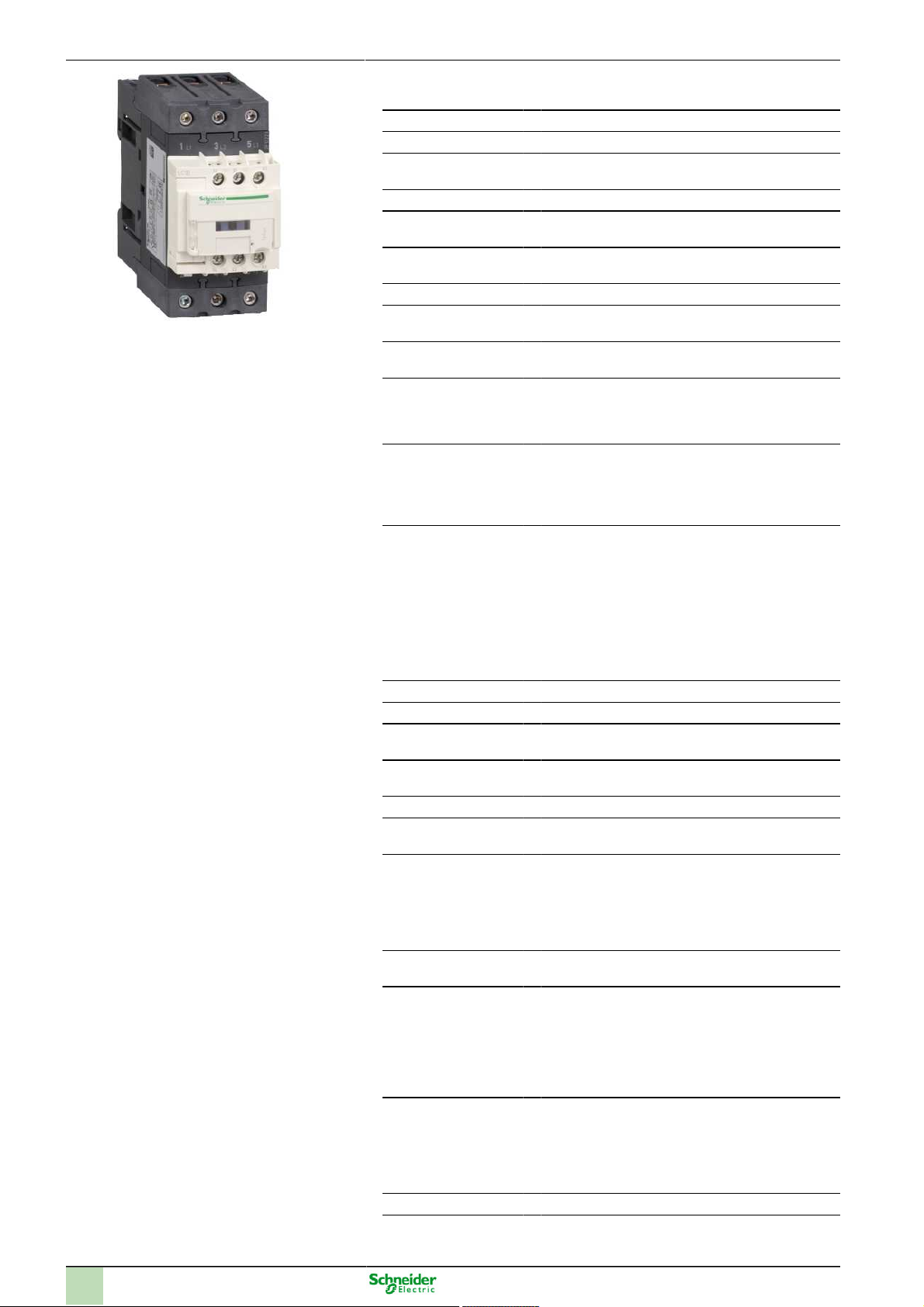
LC1D40AFE7
TeSys D contactor - 3P(3 NO) - AC-3 - <= 440
V 40 A - 115 V AC 50/60 Hz coil
Sep 19, 2016
1
Page 2
Main
Range TeSys
Product name TeSys D
Product or component
type
Device short name LC1D
Contactor application Motor control
Utilisation category AC-1
Poles description 3P
Power pole contact
composition
[Ue] rated operational
voltage
[Ie] rated operational
current
Motor power kW 11 kW at 220...230 V AC 50/60 Hz
Motor power HP (UL /
CSA)
Control circuit type AC 50/60 Hz
Control circuit voltage 115 V AC 50/60 Hz
Auxiliary contact composition
[Uimp] rated impulse
withstand voltage
Overvoltage category III
[Ith] conventional free
air thermal current
Irms rated making capacity
Rated breaking capacity
[Icw] rated short-time
withstand current
Associated fuse rating 10 A gG for signalling circuit conforming to IEC
Average impedance 1.5 mOhm at 50 Hz - Ith 60 A for power circuit
Contactor
Resistive load
AC-3
3 NO
<= 690 V AC 25...400 Hz for power circuit
<= 300 V DC for power circuit
60 A (<= 60 °C) at <= 440 V AC AC-1 for power circuit
40 A (<= 60 °C) at <= 440 V AC AC-3 for power circuit
18.5 kW at 380...400 V AC 50/60 Hz
22 kW at 415...440 V AC 50/60 Hz
22 kW at 500 V AC 50/60 Hz
30 kW at 660...690 V AC 50/60 Hz
5 hp at 230/240 V AC 50/60 Hz for 1 phase motors
10 hp at 230/240 V AC 50/60 Hz for 3 phases motors
30 hp at 575/600 V AC 50/60 Hz for 3 phases motors
10 hp at 200/208 V AC 50/60 Hz for 3 phases motors
3 hp at 115 V AC 50/60 Hz for 1 phase motors
30 hp at 460/480 V AC 50/60 Hz for 3 phases motors
1 NO + 1 NC
6 kV conforming to IEC 60947
10 A at <= 60 °C for signalling circuit
60 A at <= 60 °C for power circuit
140 A AC for signalling circuit conforming to IEC
60947-5-1
250 A DC for signalling circuit conforming to IEC
60947-5-1
800 A at 440 V for power circuit conforming to IEC
60947
800 A at 440 V for power circuit conforming to IEC
60947
320 A <= 40 °C 10 s power circuit
720 A <= 40 °C 1 s power circuit
72 A <= 40 °C 10 min power circuit
165 A <= 40 °C 1 min power circuit
100 A 1 s signalling circuit
120 A 500 ms signalling circuit
140 A 100 ms signalling circuit
60947-5-1
80 A gG at <= 690 V coordination type 1 for power
circuit
80 A gG at <= 690 V coordination type 2 for power
circuit
2
Page 3

[Ui] rated insulation
voltage
Electrical durability 1.4 Mcycles 60 A AC-1 at Ue <= 440 V
Power dissipation per
pole
Safety cover With
Mounting support Plate
Standards CSA C22.2 No 14
Product certifications CCC
Connections - terminals Control circuit : screw clamp terminals 2 cable(s)
Tightening torque Control circuit : 1.7 N.m - on screw clamp terminals -
Operating time 4...19 ms opening
Safety reliability level B10d = 1369863 cycles contactor with nominal load
Mechanical durability 6 Mcycles
Operating rate 3600 cyc/h at <= 60 °C
600 V for power circuit certifications CSA
600 V for power circuit certifications UL
690 V for signalling circuit conforming to IEC
60947-1
600 V for signalling circuit certifications CSA
600 V for signalling circuit certifications UL
690 V for power circuit conforming to IEC 60947-4-1
1.5 Mcycles 40 A AC-3 at Ue <= 440 V
2.4 W AC-3
5.4 W AC-1
Rail
EN 60947-4-1
EN 60947-5-1
IEC 60947-4-1
IEC 60947-5-1
UL 508
CSA
GOST
UL
1...2.5 mm² - cable stiffness: flexible - with cable end
Control circuit : screw clamp terminals 1 cable(s)
1...4 mm² - cable stiffness: flexible - without cable
end
Control circuit : screw clamp terminals 2 cable(s)
1...4 mm² - cable stiffness: flexible - without cable
end
Control circuit : screw clamp terminals 1 cable(s)
1...4 mm² - cable stiffness: flexible - with cable end
Control circuit : screw clamp terminals 1 cable(s)
1...4 mm² - cable stiffness: solid - without cable end
Control circuit : screw clamp terminals 2 cable(s)
1...4 mm² - cable stiffness: solid - without cable end
Power circuit : EverLink BTR screw connectors 1
cable(s) 1...35 mm² - cable stiffness: flexible - without
cable end
Power circuit : EverLink BTR screw connectors 2
cable(s) 1...25 mm² - cable stiffness: flexible - without
cable end
Power circuit : EverLink BTR screw connectors 1
cable(s) 1...35 mm² - cable stiffness: flexible - with
cable end
Power circuit : EverLink BTR screw connectors 2
cable(s) 1...25 mm² - cable stiffness: flexible - with
cable end
Power circuit : EverLink BTR screw connectors 1
cable(s) 1...35 mm² - cable stiffness: solid - without
cable end
Power circuit : EverLink BTR screw connectors 2
cable(s) 1...25 mm² - cable stiffness: solid - without
cable end
with screwdriver flat Ø 6 mm
Control circuit : 1.7 N.m - on screw clamp terminals with screwdriver Philips No 2
Power circuit : 5 N.m - on EverLink BTR screw connectors - cable <= 25 mm² hexagonal 4 mm
Power circuit : 8 N.m - on EverLink BTR screw connectors - cable 25...35 mm² hexagonal 4 mm
12...26 ms closing
conforming to EN/ISO 13849-1
B10d = 20000000 cycles contactor with mechanical
load conforming to EN/ISO 13849-1
3
Page 4
Complementary
Coil technology Without built-in suppressor module
Control circuit voltage limits 0.3...0.6 Uc at 60 °C drop-out 50/60 Hz
Inrush power in VA 140 VA at 20 °C (cos ϕ 0.75) 60 Hz
Hold-in power consumption in VA 13 VA at 20 °C (cos ϕ 0.3) 60 Hz
Heat dissipation 4...5 W at 50/60 Hz
Auxiliary contacts type Type mechanically linked (1 NO + 1 NC) conforming to IEC 60947-5-1
Signalling circuit frequency 25...400 Hz
Minimum switching current 5 mA for signalling circuit
Minimum switching voltage 17 V for signalling circuit
Non-overlap time 1.5 ms on de-energisation (between NC and NO contact)
Insulation resistance > 10 MOhm for signalling circuit
0.8...1.1 Uc at 60 °C operational 50 Hz
0.85...1.1 Uc at 60 °C operational 60 Hz
160 VA at 20 °C (cos ϕ 0.75) 50 Hz
15 VA at 20 °C (cos ϕ 0.3) 50 Hz
Type mirror contact (1 NC) conforming to IEC 60947-4-1
1.5 ms on energisation (between NC and NO contact)
Environment
IP degree of protection IP2x front face conforming to IEC 60529
Protective treatment TH conforming to IEC 60068-2-30
Pollution degree 3
Ambient air temperature for operation -5...60 °C
Ambient air temperature for storage -60...80 °C
Permissible ambient air temperature around the device
Operating altitude 3000 m without derating in temperature
Fire resistance 850 °C conforming to IEC 60695-2-1
Flame retardance V1 conforming to UL 94
Mechanical robustness Vibrations contactor open 2 Gn, 5...300 Hz
Height 122 mm
Width 55 mm
Depth 120 mm
Product weight 0.85 kg
-40...70 °C at Uc
Vibrations contactor closed 4 Gn, 5...300 Hz
Shocks contactor closed 15 Gn for 11 ms
Shocks contactor open 10 Gn for 11 ms
Offer Sustainability
Sustainable offer status Green Premium product
RoHS (date code: YYWW)
REACh Reference not containing SVHC above the threshold
Product environmental profile
Product end of life instructions
4
Compliant - since 0001 - Schneider Electric declaration of conformity
Available Download Product Environmental
Available Download End Of Life Manual
 Loading...